CALIFORNIA ACCENT LIGHTING, INC.
2820 E. Gretta Lane, Anaheim, CA 92806
© CALI. All rights reserved. CALI reserves the right to make changes or withdraw specifications without prior notice.
1 / 29 / 2021 / Rev 2
Page 5 of 16
ALS500T-RMW-MI
INSTALLATION INSTRUCTIONS
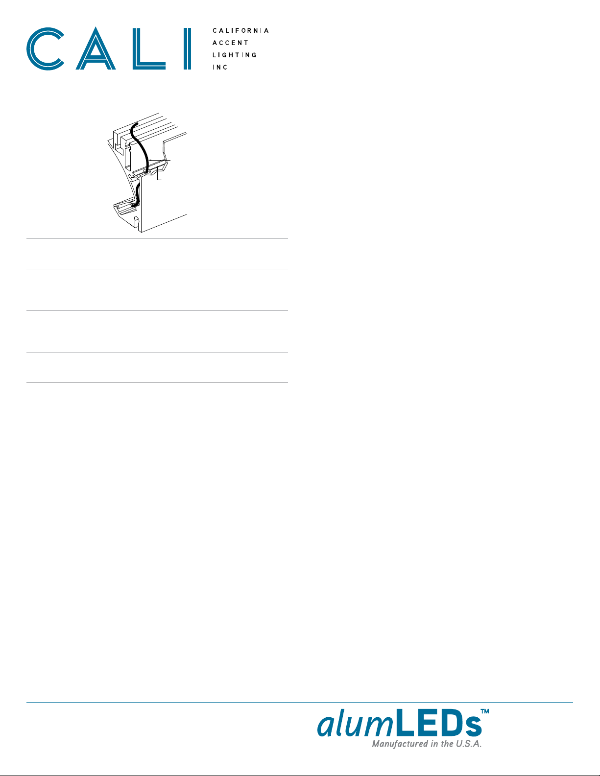
Mounting (Hanging Bracket Assembly ) 2 of 2
Tighten hex nuts as needed
Mud-In Ceiling Trim flush with
projected location of ceiling drywall
Ceiling Line
Slide luminaire with Hanging
Bracket Arms onto Rail Bracket
Lead Wire
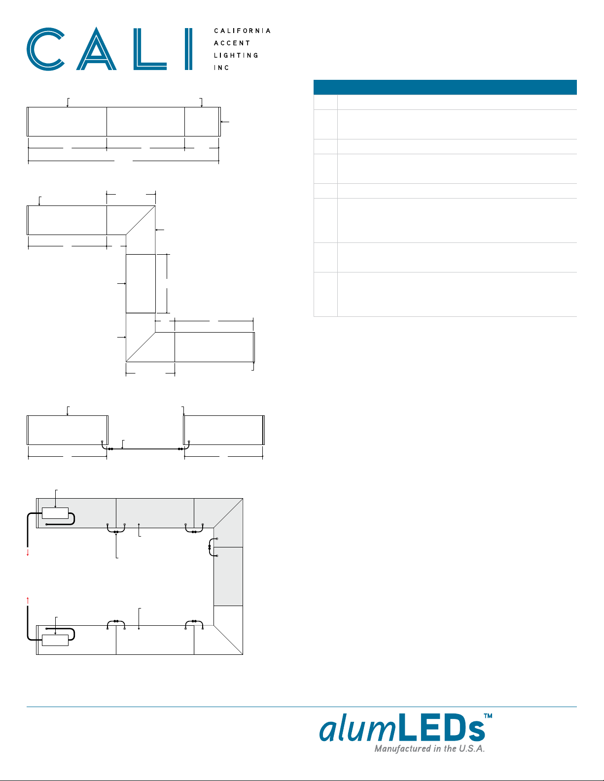
Secure connections between continuous runs using Connector Blocks after all
luminaires have been mounted.
Note: Refer to steps on page 12 for details.
10
Install Ceiling Trim after all runs have been mounted and connected.
Note: Follow the steps on page 13 to install Ceiling Trim.
11
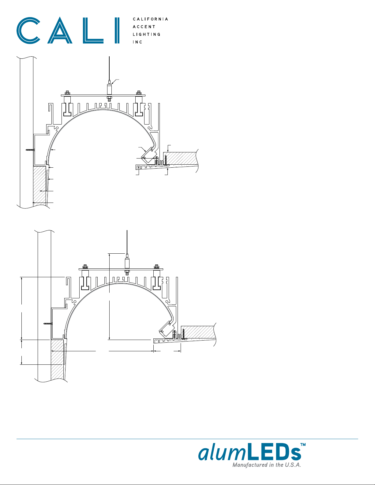
After all luminaires are mounted, adjust height and levelness of each luminaire
by tightening or loosening hex nuts on Hanging Bracket assembly. Use a dummy
piece of drywall to perfect the height at which the luminaires will rest.
The drywall will be tucked into the gap between the Mud-In Ceiling Trim and the
concealed ceiling grid when hung.
Note: One person holds the luminaire and another person adjusts hex nuts.
12
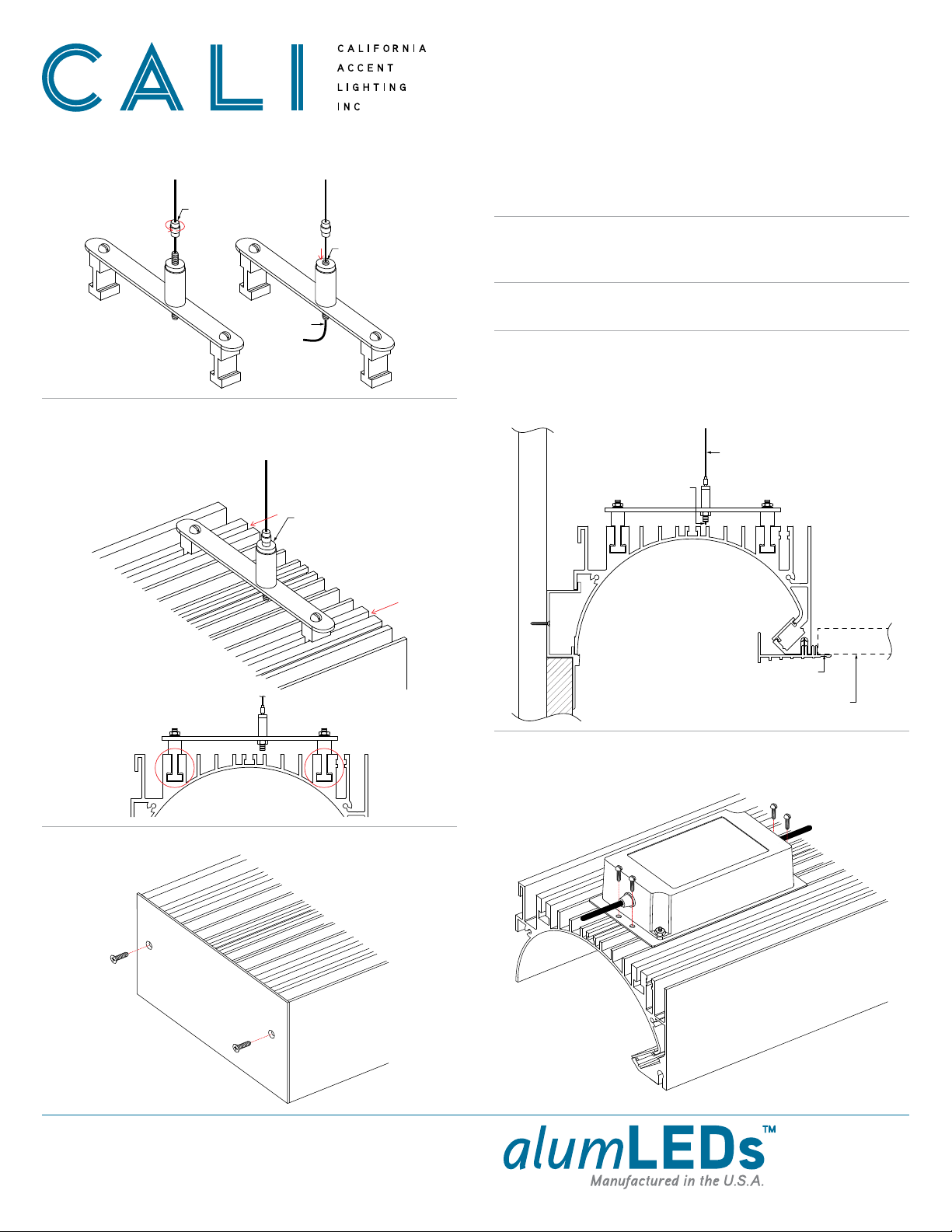
Secure a tie wire to each Hanging Bracket Arm after luminaires are set in place.
Note: Refer to the diagrams on page 3 for details.
13
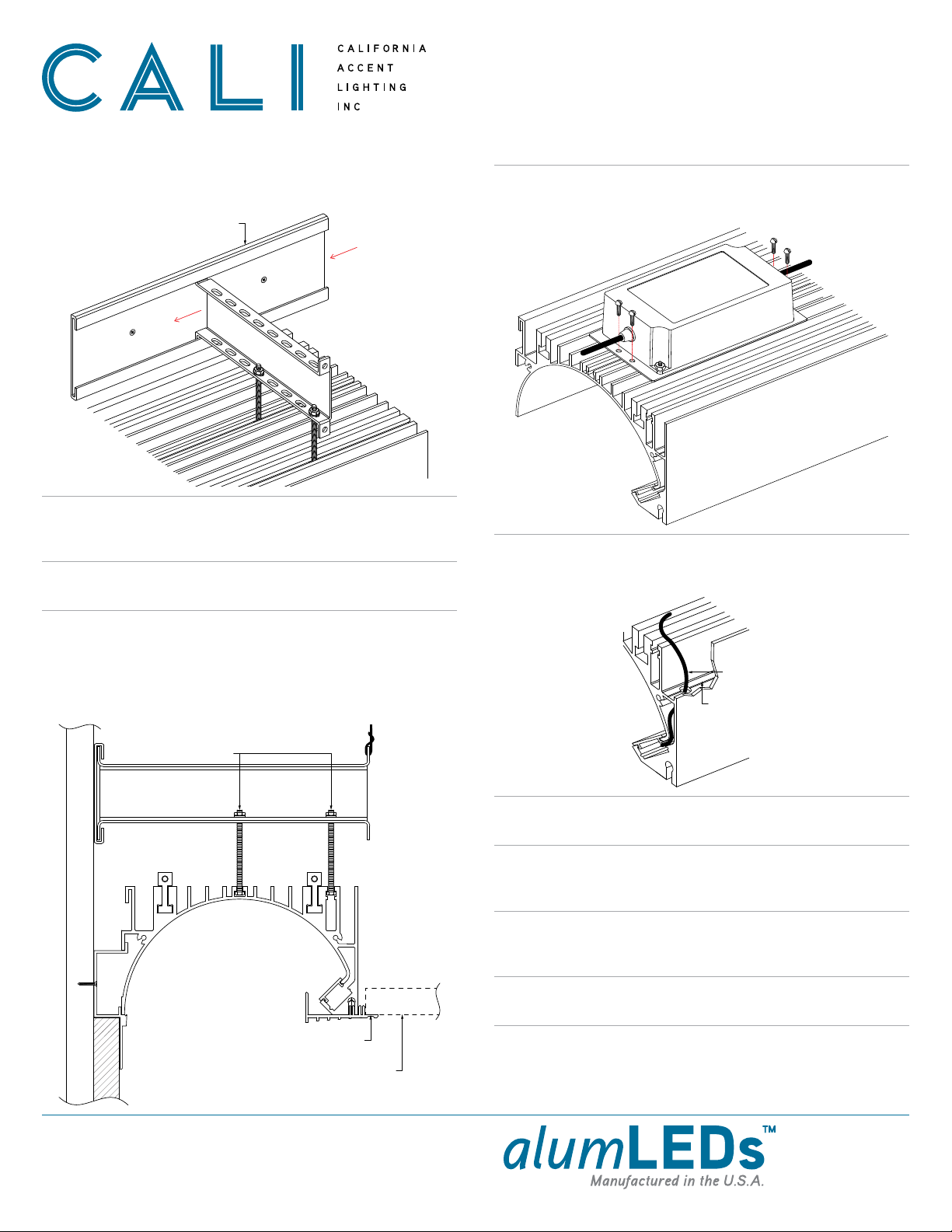
If applicable, position the driver in the center of luminaire and secure using set
screws (by others). Do not mount drivers between luminaires.
Note: Driver size and location of mounting holes may differ from below example.
14
Make wiring connections from driver to 1st PCB. Pull lead wires from luminaire
and make splice connections to lead wires from driver. Verify wiring diagram
before connecting.
15
Verify driver wire colors from wiring diagram, then connect luminaires to power
source. Drivers used for this product vary. Always confirm wiring diagram from
driver installation instructions before connecting.
17
After all installation steps are complete and lighting is confirmed to be working,
install reflective film to runs.
Note: Follow the steps on page 15 to install reflective film.
20
Perform a continuity test before connecting luminaire to power source.
Refer to page 15 for continuity test step by step.
16
Apply mud to trims until completely covered and smooth. Allow to dry completely
before painting or sanding. Do not use pre-mixed mud compounds.
19
Verify that all Ceiling Trims are securely leveled, then screw trim to drywall
using countersink screws. Use 1 screw per 2’ of trim, rounded up. Drill additional
holes in ceiling trim if necessary.
18
Mount luminaire to Rail Brackets by sliding luminaire with assembled Hanging
Bracket Arms into Rail Brackets. Ensure each Hanging Bracket rests at the
center of each Rail Bracket.
Note: All Hex Head Bolts must be vertical after mounting luminaire. If bolts are
crooked or slanted, the Hanging Bracket must be adjusted.
9