California PRO 1005 User manual

California Air Tools PRO 1005
Composite Orbital Sander
Model No.: PRO 1005

Technical Data
Sanding Pad………………………………………………………………………..5” (125 mm)/6"(150 mm)
Free speed…………………………………………………………………………10,000 rpm
Air consumption…...……………………………………………………………….2.8 cfm (79.2 l/min)
Operating pressure………………………………………………………………..90 psi (6.3 bar)
Air inlet size…………………………………………………………………………1/4”
Air hose size………………………………………………………………………..3/8”
Weight………………………………………………………………………………2.30Lbs (1.05kgs)
A-Weighted sound pressure level………………………………………………..89.0 dB (A)
Sound power level…………………………………………………………………100.0 dB (A)
Vibration in the handle…………………………………………………………… 18.30m/s2
Important Safety Rules
1. Always wear safety goggles or glasses.
2. Always ensure machine is switched off before connecting to air supply.
3. Disconnect any machine from the air supply before changing blades or discs, and before servicing any
type of machine.
4. Always keep your air tool clean and lubricated. Daily lubrication is essential to avoid internal corrosion
and possible failure.
5. Do not wear watches, rings bracelets or loose clothing when using air tools.
6. Using only light weight coil hoses from a tool to the wall or compressor coupling.
Do not fit quick change couplings onto the machine as vibration can cause the coupling to fail.
7. Do not overload the machine. Allow the tool to operate at its optimum speed for maximum efficiency.
8. Do not increase the air pressure above the manufacturers recommended level of 8 bar, as excessive
overload can cause the machine casing to split. Also this creates excessive wear on moving parts and
possible failure.
9. In the interests of safety and possible damage to the machine/operator, always ensure that the
machine has stopped before putting it down after use.
10. Always ensure that the work piece is firmly secured leaving both hands free to control the machine.
11. Always ensure that the accessories such as blades, discs, sockets, etc. are rated/designed for use
with the machine.
Also correctly and securely fastened before connecting the machine to the air supply.
12. When grinding, sanding or cutting always wear an appropriate face mask or respiratory equipment.
Operating Instruction
Description
The California Air Tools PRO 1005 Composite Orbital Sander is designed with the professional in mind.
The lightweight (2.3 lbs) composite body and rear exhaust reduces fatigue during a job. Operating at
10,000 RPM and using 2.8 CFM 90 PSI make sanding very easy. Includes a 5” pad.

Air supply
1. Ensure tool air valve (or trigger) is in the “off” position before connecting to the air supply.
2. You will require 90 PSI of air pressure 2.8 CFM of air flow.
3. WARNING! Ensure the air supply is clean and does not exceed 8bar (120psi) while operating the sander.
Too high air pressure and unclean air will shorten the product life due to excessive wear, and may be
dangerous causing damage and/or personal injury.
4. Drain the air tank daily. Water in the air line will damage the machine.
5. Clean air inlet filter weekly. Recommended hook-up procedure is shown in fig 1.
6. Line pressure should be increased to compensate for unusually long air hoses.
The minimum hose diameter should be 1/4” I.D. and fittings must have the same inside dimensions.
7. Keep hose away from heat, oil and sharp edges. Check hose for wear, and make certain that all
connections are secure.
Lubrication
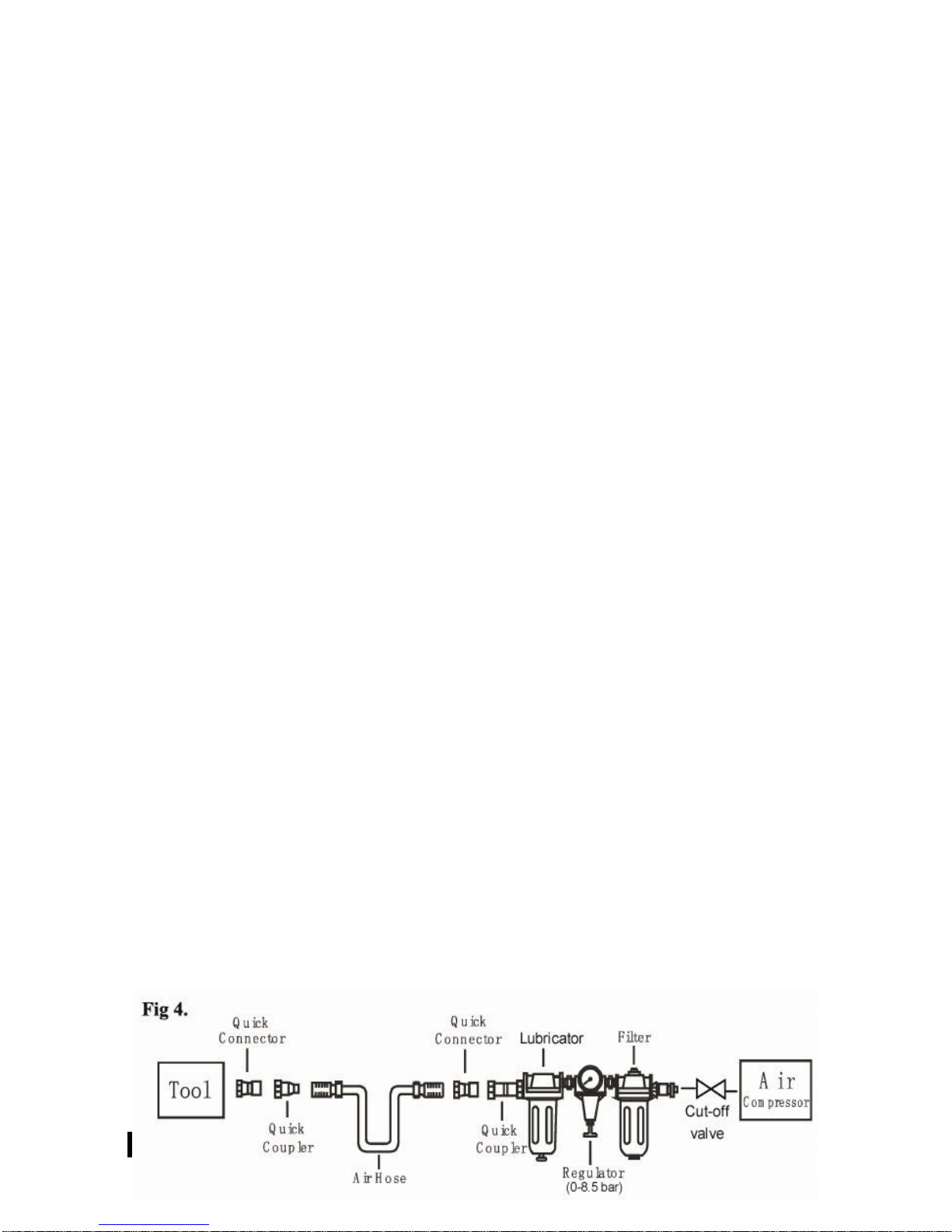
An automatic in-line filter-regulator-lubricator is recommended (Fig4) as it increases tool life and keeps
the tool in sustained operation.
The in-line lubricator should be regularly checked and filled with air tool oil.
Proper adjustment of the in-line lubricator is performed by placing a sheet of paper next to the exhaust
ports and holding the throttle open approximately 30 seconds. The lubricator is properly set when a light
stain of oil collects on the paper. Excessive amounts of oil should be avoided.
In the event that it becomes necessary to store the tool for an extended period of time (overnight,
weekend, etc.), it should receive a generous amount of lubrication at that time. The tool should be run for
approximately 30 seconds to ensure oil has been evenly distributed throughout the tool. The tool should
be stored in a clean and dry environment.
It is most important that the tool be properly lubricated by keeping the air line lubricator filled and
correctly adjusted. Without proper lubrication the tool will not work properly and parts will wear
prematurely.
Use the proper lubricant in the air line lubricator. The lubricator should be of low air flow or changing
air flow type, and should be kept filled to the correct level. Use only recommended lubricants,
specially made for pneumatic applications. Substitutes may harm the rubber compounds in the tools
O-rings and other rubber parts.
IMPORTANT!!!
If a filter/regulator/lubricator is not installed on the air system, air operated tools should be lubricated at
least once a day or after 2 hours work with 2 to 6 drops of oil, depending on the work environment,
directly through the male fitting in the tool housing.
Loading and operation
WARNING: Ensure you read, understand and apply safety instructions before use.

1. As a standard practice, drain water from the air compressor tank and air lines prior to use each
day (reference your compressor operators manual for detailed instructions).
2. Install a 1/4” male connector (not included) into the air inlet port on the tool.
3. Turn on the air compressor and allow it to build up pressure.
4. To assemble the backing disks and sandpaper.
5. Adjust the air compressor’s regulator or the supply line regulator to 90PSI.
6. Connect the tool to the air hose quick coupler.
7. Adjust the regulator control knob to the desired variable speed.
8. Squeeze trigger gently. Start the sander off the work. Set it down on the outer portion of the sandpaper
with tool held at a slight angle to the work surface. Move the sander slowly back and forth in wide
overlapping areas. Let the sander do the work surface. Do not put additional pressure on the sander.
This slows down the speed of the pad, reducing sanding efficiency and puts additional burden on the
air tool motor.
9. When finishing sanding, lift sander off the work before releasing the trigger.
Maintenance
WARNING:
Disconnect tools from air supply before changing accessories, servicing or performing maintenance.
Replace or repair damaged parts. Use genuine parts only. Non-authorized parts may be dangerous and
will invalidate the warranty.
1. Lubricate the air sander daily with a few drops of air tool oil dripped into the air inlet
2. Clean the tool after use. DO NOT use worn or damaged tool.
3. Loss of power or erratic action may be due to the following:
a) Excessive drain on the air line. Moisture or restriction in the air pipe. Incorrect size or type of hose
connectors. To remedy check the air supply.
b) Grit or gum deposits in the tool may also reduce performance. If your model has an air strainer
(located in the area of the air inlet), remove the strainer and clean it.
4. When not in use, disconnect from air supply, clean tool and store in a safe, dry, childproof location.
Trouble Shooting
The following form lists the common operating system with problem and solutions. Please read the form
carefully and follow it.
WARNING:
If any of the following symptoms appears during your operating, stop using the tool immediately, or
serious personal injury could result. Only a qualified persons or an authorized service center can perform
repairs or replacement of tool.
Disconnect tool from air supply before attempting repair or adjustment. When replacing O-rings or
Cylinder, lubricate with air tool oil before assembly.

PROBLEMS
POSSIBLE CAUSES
REMEDIES
Tool runs at normal
speed but loses under
load
■. Motor parts worn.
■Cam clutch worn or sticking
due to lack of lubricant.
■Lubricating clutch housing.
■ Check for excess clutch oil. Clutch cases
need only be half full. Overfilling
Can cause drag on high speed clutch parts,
i.e. a typical oiled/lubricated wrench requires
1⁄2 ounce of oil.
GREASE LUBRICATED: NOTE: Heat usually
indicates insufficient grease in chamber.
Severe operating conditions may require more
frequent lubrication.
Tool runs slowly. Air
flows slightly from
exhaust
■ Motor parts jammed with dirt
particles
■Power regulator in closed
position
■Air flow blocked by dirt.
■Check air inlet filters for blockage.
■ Pour air tool lubricating oil into air inlet as per
instructions.
■Operate tool in short bursts quickly reversing
rotation back and forth where applicable.
■ Repeat above as needed. If this fails return to
service centre.
Tools will not run. Air
flows freely from
exhaust
■One or more motor vanes
stuck due to material build up.
■ Pour air tool lubricating tool into air inlet.
■Operate tool in short bursts of forward and/or
reverse rotation where applicable.
■ Tap motor housing gently with plastic mallet.
■ Disconnect supply. Free motor by rotating drive
shank manually where applicable
■ If tool remains jammed return to service
centre.
Tool will not shut off
■‘O’ rings throttle valve
dislodged from seat inlet
valve.
■Trigger valve curved or
blocked by dirt
■Replace ‘O’ ring
■Lubricate the trigger valve with special
lubrication. Or send the service center.
Motor will not run
■The inside of Motor blocked
by dirt
■Lubricate the motor and operate tool
■Operate tool in short bursts of forward and/or
reverse rotation where applicable.
■ If tool remains jammed return to service
centre.
Sanding paper cannot
stick to the pad
■Sanding pad damaged or
dirty
■Replace the sanding pad
Note: Repairs should be carried out by a qualified person.

Exploding view
Spare part list
No.
Description
NO
Description
No.
Description
No.
Description
1
Rubber Grip
14
Cylinder Front Plate
27
Bolt M4×10
40
Regulator
2
Housing
15
Gasket
28
Jacket
41
Pin 2×19
3
Bolt M5×0.8×4.3
16
Bearing Washer
29
Sanding Pad
42
Bolt
4
Washer
17
Washer
30
Trigger
43
O-ring 16.5×1.8
5
Ball Bearing
18
Semicircular key
31
Snap-Retainer
44
Air Outlet
6
Gasket
19
Anvil
32
Pin
45
Three Way Connector
7
Pin 3×14
20
Retainer Ring
33
O-ring 10×1.8
46
Two Way Connector
8
Cylinder End Plate
21
Ball Bearing
34
Valve Stem Cover
47
Muffle Cover
9
Cylinder
22
Dustproof Mat
35
O-ring 2×1.0
48
Pin 3×7
10
O-ring 47.5×2.65
23
Bearing Washer
36
O-ring 4×1.5
49
Bolt M5×4
11
Rotor Blade
24
Retainer Ring
37
Valve Stem
50
Air Inlet
12
Rotor
25
Principal Axis
38
Spring
51
Spanner
13
Pin 3×6
26
Airproof Cap
39
O-ring 6×1.8
If you need spare parts of this model, contact us or the distributor where you bought this tool.

Limited Warranty
This Warranty is Limited to CALIFORNIA AIR TOOLS and SPRAYIT Products.
Limited Warranty: 1 Year
CALIFORNIA AIR TOOLS, Inc. will repair or replace, free of charge, to the original retail
customer whom purchased a CALIFORNIA AIR TOOLS or SPRAYIT product from an authorized
dealer, distributor or distributor’s dealer.
This warranty does not transfer to subsequent owners.
CALIFORNIA AIR TOOLS, Inc. will repair or replace, at its option, any parts that are proven by an
authorized service center to be defective in material or workmanship under normal use
during the applicable warranty time period as stated above.
This limited warranty covers the cost of the replacement parts and labor for all defects when
installed by an authorized service center.
Transportation charges are the responsibility of the customer.
Any part replaced under warranty becomes the property of CALIFORNIA AIR TOOL, Inc.
All parts replaced under warranty will be considered as part of the original product, and any
warranty on those parts will expire coincident with the original product warranty.
The limited warranty period begins on the date of the retail purchase by the original
purchaser.
CALIFORNIA AIR TOOL, Inc.
8560 Siempre Viva Road, Unit 3A
San Diego, California 92154
Tel: (866) 409-4581
Fax (619) 424-8697
info@CALIFORNIAAIRTOOLS.com
www.CALIFORNIAAIRTOOLS.com
Table of contents