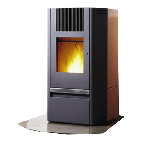
calimax PWS 0601-A User manual

Operating Manual
PWS 0601-A and PWS 1201-A
(Models Twist 6 + Twist 12)
English

Version: st 110208 PWS 0601-A & PWS 1201-A BA_EN
Article nu ber: 102471
Fro SW 2.03
All infor ation subject to change. All rights reserved.

1
Table of Contents
1 Preface ............................................................................................................ 2
2 I portant notes ............................................................................................... 2
2.1 Safety ...................................................................................................................................... 2
2.2 Identification ............................................................................................................................ 3
2.3 Liability .................................................................................................................................... 3
2.4 Notes on legal regulations ......................................................................................................... 3
2.5 Stove-related hazards ............................................................................................................... 4
3 Approved fuel................................................................................................... 4
3.1 Storage of pellets...................................................................................................................... 4
4 Construction of the stove .................................................................................. 5
4.1 Standard accessory ................................................................................................................... 5
4.2 Front view ................................................................................................................................ 5
4.3 Rear view ................................................................................................................................. 6
5 Installation....................................................................................................... 7
5.1 Mini u distances ................................................................................................................... 7
5.2 Flue ......................................................................................................................................... 8
5.3 Connecting piece, pellet stove - chi ney.................................................................................... 8
5.4 Co bustion air ......................................................................................................................... 8
5.4.1 Intake fro external source (preferred) ..................................................................................... 8
5.4.2 Intake fro internal source ....................................................................................................... 9
5.5 Flue with air intake syste (AIS) ............................................................................................... 9
5.6 Non-dependence on a bient air ................................................................................................ 9
5.7 Backflow syste ....................................................................................................................... 9
6 Control syste ax3 ...................................................................................... 10
6.1 Operating odes .................................................................................................................... 10
6.2 Overview of user and service enus ........................................................................................ 11
6.3 External require ent............................................................................................................... 12
7 Start-up, operating ode................................................................................ 13
7.1 Filling the pellet bin................................................................................................................. 13
7.2 Functional characteristics of the heating operation.................................................................... 13
7.2.1 Self-test ................................................................................................................................. 13
7.2.2 Starting phase, pre-heating phase ........................................................................................... 13
7.2.3 Heating phase ........................................................................................................................ 13
7.2.4 Cleaning phase ....................................................................................................................... 13
7.2.5 Cool-down phase: ................................................................................................................... 13
7.2.6 Standby.................................................................................................................................. 13
7.3 Heating ode......................................................................................................................... 14
7.4 Perfor ance-regulated heating ode....................................................................................... 14
7.5 Setting date / ti e.................................................................................................................. 15
7.6 Setting ti er switch ................................................................................................................ 15
7.7 External control with internal ti er switch ................................................................................ 16
7.8 Activating the ti er switch ...................................................................................................... 16
7.9 Resetting to factory settings .................................................................................................... 16
8 Cleaning and aintenance .............................................................................. 17
8.1 After 200 kg or 14 days........................................................................................................... 17
8.2 After 800 kg or annually .......................................................................................................... 18
9 Errors - causes - re edies .............................................................................. 20
9.1 Service request....................................................................................................................... 21
10 Technical data................................................................................................ 22
10.1 Di ensions............................................................................................................................. 23
11 Confor ity..................................................................................................... 25
12 Notes............................................................................................................. 27
2
1 Preface
Thank you for choosing one of our products.
Please inspect the pellet stove upon arrival very carefully for da age and co pleteness of the accessory
equip ent included with delivery.
2 Important notes
2.1 Safety
Before installing your appliance and starting it, please take care to read the operating anual in detail. This
will ensure that you avoid da age caused by incorrect installation or operation.
To carry your pellet stove only approved conveying equip ent with a sufficient load rating ay be used.
When burning pellets, heat energy is released causing intensive heating of the stove surface and glass door.
If these parts are touched without using appropriate protective clothing, or aids such as e.g. suitable gloves,
there is a risk of burns.
Draw your children's attention to this specific danger and keep the away fro the heating appliance whilst
it is operating.
Placing infla able objects on or close to the heating appliance is prohibited.
The pellet stove ay only be connected to the ains supply after it has been connected to the flue by an
approved specialist.
Do not place ite s of washing on the stove to dry.
When drying ite s of clothing and suchlike, they ust be positioned sufficiently well away fro the stove
(fire risk)!
Using or working with highly co bustible or explosive aterials in the sa e roo or adjoining roo s whilst
your stove is in operation, is prohibited.
Filling the pellet bin:
The opening of the pellet bin is sufficiently large to allow it to be easily filled.
Take care to ensure that no pellets fall onto the grill of the vent, or the body of the hot stove. This could
cause for ation of dense s oke.
Never operate the stove with the glass door or the pellet bin open. A flash fire or isfire could be caused.
Never re ove the safety equip ent such as grills etc..
Always re ove the ains plug before doing any work.
Make certain that there is always sufficient co bustion air in the roo where the stove is set up in.
The pellet stove is only designed to use standard low-dust wood pellets according to EN 14961-2 (class 1).
If weather-related conditions, such as positive pressure in the chi ney for exa ple, are prevalent, the stove
ust not be started.
The stoves are designed to be used in do estic living spaces with nor al hu idity and te peratures of 0 °C
to 30 °C. Stoves are not protected against water splashing and ust not be installed in wet roo s.

3
Suitable antifreeze (approved for use in solar syste s) ust be used for stoves with water heat exchangers
where roo te peratures are < 5 °C.
2.2 Identification
The docu entation included with delivery will assist with:
• operating the pellet stove safely
• exploiting all potential for use of the stove
• perfor ing cleaning and aintenance work
This operating anual should be kept in good condition and in an easily accessible location until the stove is
disposed of. It should be given to any new owner(s).
If the operating anual is lost or destroyed, a new copy can be requested any ti e fro your specialist
dealer.
The illustrations and sketches are intended as basic infor ation only. They are not to scale.
Directional infor ation such as „right/left, front/back“ always relates to the position facing the front of the
pellet stove.
ISO units of easure ent are used for di ensions, which are given in unless otherwise indicated.
2.3 Liability
In the event of personal injury or property da age, the anufacturer shall be responsible for the building
standard and safety of the achine only if design defects can be verified.
No liability for:
• inappropriate use
• inappropriate operation
• inadequate aintenance
• use of non-original spare parts
• structural odifications
Non-intended use
Inappropriate use of the pellet stove can result in life-threatening injuries and other ajor property da age
as well as in loss of warranty.
Uses not confor ing to the intended use are:
• any structural odification of the pellet stove
• operation without proper connection to the flue
• operation with open doors and covers
• operation without knowledge of the operating anual
• installation of non-original spare parts
• use of wood pellets that are not approved by the anufacturer
2. Notes on legal regulations
Please observe local, national and European regulations and standards applicable for the installation and
operation of co bustion appliances.

4
2.5 Stove-related hazards
Danger of fire / burn injuries
• The pellet stove ust never be used with open doors or covers; sparks or fla es could be released.
• Never cover the stove with blankets, towels or si ilar ite s. During operation, various surfaces reach
te peratures of over 65 °C. The aterials could catch fire.
• If required, please use suitable protective equip ent.
Chi ney fire or burnback
• Never pull the power plug and keep closed all doors and covers. Open windows and doors.
Poisoning and suffocation hazard
• The flue gases contain har ful constituents, including carbon onoxide. This gas is odourless and
poisonous.
• Self-protective action for rescuing unconscious persons: thoroughly ventilate closed roo s before
entering.
Electrocution hazard
• For power supply voltages of 50 Hz and an exposure ti e of ore than one second, the following
applies:
Currents higher than 50 A and voltages of 50 V or higher are extre ely dangerous.
Power cut
• Never open the doors or the bin lid during a power cut. Poisonous gases could be released.
• Following a short power cut, the heating ode is auto atically continued.
• After a longer power cut, the stove first switches to cool-down ode and subsequently to starting
phase.
3 Approved fuel
The require ents for approved fuel are defined in the
EN 14961-2 (class A1), EN plus (class A1) or
ÖNORM M7135, DIN 51731, DIN Plus standards. Low-dust wood pellets are to be used.
Length 10 - 30
Dia eter 6 or 8 *)
Bulk density 650 kg/ ³
Calorific value 5 kWh/kg
Residual oisture < 10 %
Ash content < 0.5 %
Density 1.12 kg/d ³
*) Manual adjust ents by the service engineer are necessary!
ATTENTION: Waste materials and liquids are not to be burned in the stove!
3.1 Storage of pellets
To ensure co bustion of pellets without any proble s, it is necessary to store the in dry condition and
free of conta inants.

5
Construction of the stove
.1 Standard accessory
Operating anual, burn pot brush, power lead, ulti-functional tool.
.2 Front view
Transition period / su er use.
1. Dis ount deflector plate,
2. Pull out insulating plate.
Door opener
a Control panel max3
b Pellet bin lid
c Door-opening mechanism
d Glass door
e Side panel
f Insulating plates for summer use
c
f
f
a
c
d
e
f
b

6
.3 Rear view
a Voltage rating 230 V
b Safety te perature li iter (STL)
c Air-intake pipe
d Flue pipe connection Ø 100
e Opening for safety valve overflow
f Opening for heating flow or respectively return
b
a
f
c
d
e
b

7
5 Installation
5.1 Minimum distances
Mini u per issible distances to
co bustible aterials:
Rear (x): 5 c
Sides (y): 15 c
Front (z): 80 c
Reco ended per issible
distances to co bustible aterials:
Rear (x): 25 c
Sides (y): 50 c
Front (z): 80 c
Wall
Front
Floor protection:
Because the te perature in the lower areas of the pellet stove increases only ini ally during operation,
installation of a fireproof plate under the stove is not required.
Z
y
X
y

8
5.2 Flue
The flue syste is to configured according to EN 13384-1 . Before starting the pellet stove, a positive
confor ance report regarding the chi ney ust have been obtained.
Flue draught li itation:
If there is a strong flue draft (>30 Pa), a suitable auxiliary air facility is to be fitted. The local regulations
ust be followed!
Multiple-stove arrange ents with one chi ney:
Pellet stoves PWS 0601-A or PWS 1201-A with ax3 controls and integral air sensor, are suitable for
ultiple-stove arrange ents with one chi ney.
Prerequisites:
• The chi ney is to be di ensioned according to EN 13384-1 and it ust be ensured that there is a
negative pressure (greater than 1Pa).
• There is a positive report on the chi ney issued by the relevant authority.
• Regional regulations ust always be followed!
• The operator is to ensure that the stoves do not operate si ultaneously.
• That as far as the construction of the pellet stoves are concerned, it is not a just burner, but an
auto atically loaded stove with a day feed bin for burning solid bio ass fuel (pellets) and with a flue-
gas fan. This flue-gas fan conveys the flue gases into the chi ney.
• That no positive pressure can be caused in the connecting piece or in the chi ney.
Danger! Incorrect operation can result in emission of flue gases (carbon monoxide poisoning).
5.3 Connecting piece, pellet stove - chimney
The connecting piece between pellet stove and entry into the chi ney, is to be designed so that the flue
gases enter the chi ney with negligible loss of pressure or cooling (see DIN 18160). Inspection and cleaning
ust be possible. An external sleeve is sufficient to ensure tightness of the connecting piece.
5. Combustion air
5.4.1 Intake fro external source (preferred)
It is highly reco ended that co bustion air be taken in fro an external source. By this eans you ensure
that operation of the stove is independent of the a bient air, reduce energy consu ption and avoid possible
dirtying of the air sensor. Where roo ventilation or fu e extractor is fitted, air intake fro an external
source is andatory.
• Maxi u tube lengths and dia eters are to be taken fro the table.
• The end of the air extraction pipe needs to be located outside or in a well-ventilated roo inside the
building.
• The air pipe ust be designed so that no for ation of condensation is possible and that no water can
enter the stove. See DIN V 18160 standard.
• The internal surface of the air pipe ust be s ooth e.g. Geberit tubing
• A filter is to be attached across the entrance of the air intake ( esh size 1 ) to prevent s all ani als
or foreign atter entering and i peding the intake of air.
• The air-intake pipe is to incorporate a 90° downward elbow where it enters the building, so that gusts of
wind do not affect the air supply.

9
Table: Dia eters and tube lengths of the flue-gas pipe
Max. length Max. nu ber of 90° elbows
*Extension pipe Ø 75 4 3
or
*Extension pipe Ø 110 9 4
*External di ensions in
5.4.2 Intake fro internal source
The co bustion air can also be taken in fro the installation roo . The operator of the stove ust ensure
without fail that sufficient co bustion air is available (approx. 30 ³/h). Never exceed the axi u
a bient negative pressure of 4 Pa!
5.5 Flue with air intake system (AIS)
• The AIS flue syste is approved and certified for solid fuels.
• The cross-section of the connection the co bustion air intake connection fro stove to chi ney is equal
to at least the circular area of a 100 tube.
• The air duct is insulated fro the flue-gas duct. This eans that no trans ission of heat fro flue gas
to co bustion air occurs.
• The cross-sectional area of the air intake is at least equal to the circular area of a 100 tube.
• There ust be no contact between flue gas and air intake at the point of entry to the chi ney or along
its length.
5.6 Non-dependence on ambient air
The tightness of the stove confor s to Ger an require ents for solid fuel co bustion appliances non-
dependent on a bient air. The approval allows use in passive houses, low-energy houses and roo s with
controlled ventilation and external co bustion air intake.
• The test was carried out by TÜV Southern Ger any.
• Approval has been applied for to the DIBt (Deutsches Institut für Bautechnik).
• The pellet stove’s installation ust be inspected by the regional aster chi ney sweep before being
used for the first ti e (valid certificate of chi ney sweeping).
5.7 Backflow system
ATTENTION: It should be ensured that the return te perature at the intake connection to the heat
exchanger does not fall below 50 °C during heating ode. Undercutting this te perature results in corrosion
and soot for ation and thereby, destruction of the heat exchanger.
To ensure safe operation the stove is to be properly connected to a reliable heat take-out facility (buffer
tank). The requisite water quality is stipulated in Ö NORM H 5195 and is to be observed.
Without a regulation return riser the guarantee is invalidated!

10
6 Control system max3
a - Operating display with current operating ode
b - Present flow te perature
c - Start/Stop and enu display (-/+)
d - Action pads (intuitive operation)
e - Day of week and ti e of day
f - Display for required type of operation: (hand for anual operation)
• Manually, te perature, or perfor ance controlled
• Ti er switch
• External 0-10 V
• External 0/1
g - Required flow te perature (target te perature)
6.1 Operating modes
The stove can be operated in one of two different operating ode options:
• Te perature regulated 65 – 75 °C (select in enu: anual te perature)
• Auto atic operation: Heating perfor ance is selected auto atically
• Perfor ance regulated 30 % – 100 % ( enu anual perfor ance)
• Manual ode: Heating perfor ance is selected anually
The stove is supplied te perature regulated ex factory.
a
b
c
d
e
f
g

11
6.2 Overview of user and service menus
MENU
Fow temperature
Manual-Power
5 - 75°C
30 - 100%
22.7.2011
Ext. control
Ext. analog signal
Manual-Temperature
Manual-Power
Chrono-Thermostat
P01:00:00:00:00
language
Error memory list
Service
German
English
French
Italian
Code: -Nr. 01/20
Test
Revs
Flue gas fan RPM
Flue gas fan RPM
Auger motor
Open burn grate
Close burn grate
Pump
Ignition
Sensors
Flow temp.
Chamber temp.
Auger motor
Air stream
Revs
STB
Pellet tank lid
Filling level
Burn grate
Ext. Contact
Ext.Power signal
Slid temp.
Elect.board temp
Start temp. 55 - 7°C
Setup pump Yes/No
Auger motor
Info Version Stove model
Contrast Contrast
Emergency mode Air sensor
Chamber temp. sensor
Factory settings Reset
Statistics Working hours
Clock timer
Ignitions
Cleaning Clean burn brate
Date / Time
Working mode
Yes/No
Filling time
Break time
Run time motor
External filling
30min - 7h
22h00m - 0 h00m
Aktuell/Limit

12
6.3 External requirement
External require ent (0/1) (EAB)
The external requirement allows the integration of
additional components which are equipped with a
potential-free switching contact (room thermostat).
Re ove ju per EAB and connect bipolar connecting lead
of the external controls.
Applying voltage to the external
deactivation switch connector interferes
with the controls.
External analogue signal (+10 V - GND)
The external activator is used to tell the stove how uch
heat to put out (input signal: 0 – 10 VDC).
3V-30%...6V-60%...10V-100%
Applying voltages greater than 15 VDC to the
plug for the external activator interferes
with the controls.
Activate external require ent (0/1)
Activate external analogue signal (0-10 V)
The respective odes are depicted in the display by the sy bols 0/1 or 0-10 V if a signal is pending fro
the external controls. By pressing the stop key, this ode can be interrupted at any ti e. The hand sy bol
appears for anual ode.

13
7 Start-up, operating mode
7.1 Filling the pellet bin
When filling the pellet bin, take care to prevent dust for ation and spilling of pellets.
7.2 Functional characteristics of the heating operation
The pellet stove is designed for the auto atic burning of wood pellets in do estic living spaces. That eans
that the pellet stove starts up auto atically and switches itself off after the selected te perature has been
reached. The controller selects the heating output based on the set-point te perature. Thus the pellet stove
provides opti ised adjust ent of the heat output to the current require ent.
7.2.1 Self-test
To ensure safe operation of the stove, a self test is carried out before every start-up.
7.2.2 Starting phase, pre-heating phase
In this phase, auto atic ignition of the pellets is ade by electrical ignition. The fire bed is prepared so that
a s ooth transition to heating ode is effected.
7.2.3 Heating phase
Heating ode is fully auto atic; the control adapts itself to changes resulting fro burn-off loss:
• Adjust ent to pellet grade used
• Adjust ent to chi ney or installation conditions
• Continuously variable adaptation of heat output to the set-point te perature
• Opti ization of co bustion in each heating phase
• Continuous onitoring of the heating operation using sensors
There is therefore no need to ake any adjust ents to the co bustion process.
7.2.4 Cleaning phase
The heating phase is interrupted every four hours by a cleaning phase. After the cleaning, the stove returns
to the heating phase.
7.2.5 Cool-down phase:
Fuel feed is stopped in the cool-down phase and the re aining flue gases safely extracted into the chi ney.
The cool-down phase is introduced after every switching off.The cool-down phase is introduced after every
switching off.
7.2.6 Standby
If the set-point te perature has been reached, the pellet stove changes over to standby ode following the
cool-down phase. In this phase, auto atic restarting is possible at any ti e should the te perature fall
below the switch-on te perature.

14
7.3 Heating mode
Start heating ode (te perature controlled)
Start heating ode with the START key.
The stove starts heating ode and switches auto atically to standby ode
when the set-point te perature is reached. When the set-point te perature has
been undercut by 8.0 °C (adjustable fro 55-67 °C in Start Te perature enu)
the stove auto atically restarts.
Initial fill
When it is the initial operation (software update) the respective query Initial
Fill? is ade before start-up.
If the OK key is pressed the auger feed is started and filled with pellets.
Change set-point te perature of flow te perature
The set-point te perature of the stove can be varied during operation using the
–/+ keys (65 - 75 °C).
Stop heating ode
Press the Stop key to discontinue the heating operation.
Turn off the pellet stove
To prevent accidental or unintentional switching off, the safety query appears:
Switch off?
Confir with OK.
The stove ust then be restarted when required.
7. Performance-regulated heating mode
Activate operating ode "Perfor ance-Regulated"
• Select ite Mode fro the enu
• Select manual–performance
• Confir with OK
Change perfor ance
The heating perfor ance can be varied during operation using the -/+ keys
(30-100 %).
The heating ode can be stopped with the Stop key.

15
7.5 Setting date / time
Date and ti e adjust ent
• Press the Menu key in nor al operating ode
• Select Date/Time - press ↓
↓↓
↓ key 2x
• Confir with OK
Setting day
Press the key OK
• Set the date with the -/+ keys
• Confir with OK
Setting onth
• Move to next ite with ↓
↓↓
↓ key
• Press the key OK
• Subsequently proceed as for setting day
• Set year, hours, inutes and seconds in the sa e way
7.6 Setting timer switch
Progra ing the ti er switch
Press the Menu key in nor al operating ode
Select Ti e switch progra - press key ↓
↓↓
↓ 4x
Confir with OK
Ten progra able on and off cycles
are available (P01 – P10)
• Select desired progra with ↓
↓↓
↓ key (if progra ings are already available)
• Confir with OK
Progra e 01
• Press the key OK
• Exa ple: The stove heats fro 4:30 until 16:00 hrs, until the desired
te perature is reached
• Fro Monday to Sunday
• Progra the switch-on ti e with the -/+ keys
• Confir with OK
• Press key +
• Progra the switch-off ti e with the -/+ keys
• Confir with OK
• Select the desired day with the ↓
↓↓
↓ key
• Allocate the switching ti e by pressing the OK key
• Exit the enu by successively pressing the ←
←←
← key.
Up to 10 switching cycles can be progra ed and allocated to the weekdays as required.

16
7.7 External control with internal timer switch
External analogue signal (0-10 V)
Operating display stove controlled with internal ti er switch.
External require ent (0/1)
Operating display stove controlled with internal ti er switch.
7.8 Activating the timer switch
Activate the ti er switch
• Press the Menu key in nor al operating ode
• Select ode - press ↓
↓↓
↓ key 3x
• Confir with OK
Press ↓
↓↓
↓ key 4x – ti er switch is selected
Activate with key
Exit progra with ←
←←
← key
Operating display stove in operation
7.9 Resetting to factory settings
Resetting switching ti es (delete)
Should re-progra ing of the switching ti es be necessary, you can reset all
progra ed switching ti es. All ti e progra s are deleted!
• Select Reset - press ↓
↓↓
↓ key
• Confir with OK

17
8 Cleaning and maintenance
Regular cleaning and aintenance of the equip ent is the ost i portant task for the custo er, to ensure
years of trouble-free operation and achieve the highest possible perfor ance, with the greatest efficiency.
The nu ber of cleaning intervals necessary is directly dependent on the ash content of the pellets. For the
cleaning intervals described, we assu e an ash content of 0.25 %. Doubling of the ash content halves the
cleaning cycles described.
Burning wood results in the depositing of a coating on the window which, dependent upon the quality of the
pellets and perfor ance settings of the stove, can turn be white to dark. This is a natural effect of
co bustion and does not represent a fault.
Attention: Risk of injury!
Before starting to clean, shut down the stove, let it cool down and disconnect the mains plug.
Use the multi-functional tool supplied - if necessary wear protective gloves - risk of burns.
8.1 After 200 kg or 1 days
Open glass door, clean the pane
• Attach the ulti-functional tool
supplied and press to the left.
• Clean the cold pane with a da p
cloth.
Attention:
• Do not use any aggressive
cleaning agents.
Clean the firebox
Clean the firebox using a brush and the
vacuu cleaner for ashes.
Clean the burn pot
• Clean with the brush supplied.
• All bores and slots ust always be clean.
Clean the ash-compartment
• Open the locking echanis of the ash
pan.
• Re ove ash pan and e pty the ash.
• Clean out the ash co part ent using the
ulti-functional tool.

18
8.2 After 800 kg or annually
Open glass door, clean the pane
• Attach the ulti-functional tool
supplied and press to the left.
• Clean the cold pane with a da p
cloth.
Attention:
Do not use any aggressive cleaning
agents.
Clean the firebox
Clean the firebox using a brush and the
vacuu cleaner for ashes.
Clean the burn pot
• Clean with the brush supplied.
• All bores and slots ust always be clean.
Clean the ash-compartment
• Open the locking echanis of the ash
pan.
• Re ove ash pan and e pty the ash.
• Clean out the ash co part ent using the
ulti-functional tool.
Clean the heat-exchanger
• Dis ount left-hand side cover.
• Open cleaning cover top left.
• Re ove cleaning springs.
• Clean heat exchanger tube with brush.
This manual suits for next models
3
Table of contents
Other calimax Pellet Stove manuals
Popular Pellet Stove manuals by other brands

Golden Eagle
Golden Eagle Golden Eagle Wood Pellet Burning Stove Operating & installation manual

HearthStone
HearthStone Heritage 8091 owner's manual

Enviro
Enviro Maxx-1 installation manual

Enviro
Enviro M-55-FS owner's manual

Enviro
Enviro EF-V EVOLUTION Technical manual

Ashley
Ashley AP60 Owner's operation and instruction manual

Unicaterm
Unicaterm ECO 6 User and maintenance guide

Extraflame
Extraflame LUCIA user manual

Hudson River Stove Works
Hudson River Stove Works Chatham owner's manual

Palazzetti
Palazzetti Brian USE AND FUNCTION

Hearth & Home
Hearth & Home CASTILE-MBK-B installation guide

SMG
SMG ComfortBilt HP21 Operator's manual