Calira Sealine Panel 421 User manual

!
"##
Lerchenfeldstr. 9
87600 Kaufbeuren
Tel.: +49(0)8341 / 9764-0 Fax: +49(0)8341 / 67806
Betriebsanleitung
Operating Instructions
Mode d´emploi
Panel 421

$%
!
"##
Lerchenfeldstr. 9 87600 Kaufbeuren Tel.: +49(0)8341 / 9764-0 Fax: +49(0)8341 / 67806
2
Inhaltsverzeichnis
Sicherheitshinweise........................................................3
Verwendungszweck.......................................................3
Beschreibung .................................................................4
Technische Daten...........................................................5
Montage.........................................................................6
Sicherheitshinweise........................................................6
Montagedurchbruch.......................................................7
Handhabung der Käfigzugfederklemmen ......................8
Anschluss 230 Volt........................................................9
Wartungshinweise........................................................10
Instandsetzung .............................................................11
Garantie .......................................................................11
Stand: 29.04.2005
Technische Änderungen vorbehalten

$%
!
"##
Lerchenfeldstr. 9 87600 Kaufbeuren Tel.: +49(0)8341 / 9764-0 Fax: +49(0)8341 / 67806
3
Allgemeine Sicherheitshinweise aufmerksam lesen!
Achtung!
Beim Gebrauch von elektrischen Geräten sind zum Schutz vor elektrischem
Schlag, Verletzung und Brandgefahr folgende grundsätzliche Sicherheitsmaß-
nahmen zu beachten. Lesen und beachten Sie diese Hinweise, bevor Sie das
Gerät benutzen.
Aufstellen
Achten Sie darauf, dass die Geräte sicher aufgestellt werden und nicht
herabfallen oder umstürzen können. Legen Sie Leitungen stets so, dass keine
Stolpergefahr entsteht. Setzen Sie Elektrogeräte nicht dem Regen aus.
Betreiben Sie Elektrogeräte nicht in feuchter oder nasser Umgebung. Betreiben
Sie Elektrogeräte nicht in der Nähe von brennbaren Flüssigkeiten oder Gasen.
Stellen Sie Ihre elektrischen Geräte so auf, dass Kinder keinen Zugriff darauf
haben.
Schutz vor elektrischem Schlag
Betreiben Sie nur Geräte deren Gehäuse und Leitungen unbeschädigt sind.
Achten Sie auf sichere Verlegung der Kabel. Ziehen Sie nicht an den Kabeln.
Gebrauch
Benutzen Sie keine elektrischen Geräte entgegen dem, vom Hersteller
angegebenen Verwendungszweck.
Zubehör
Benutzen Sie nur Zubehörteile und Zusatzgeräte die vom Hersteller geliefert
oder empfohlen werden. Der Einsatz anderer Zubehöre birgt Gefahren.
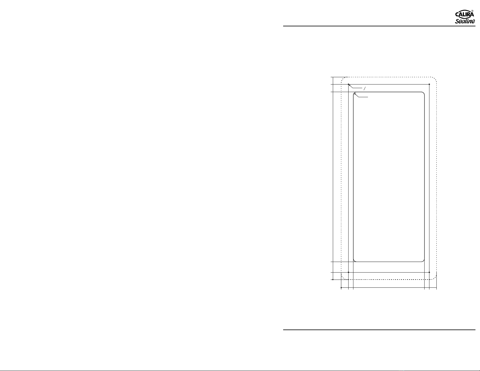
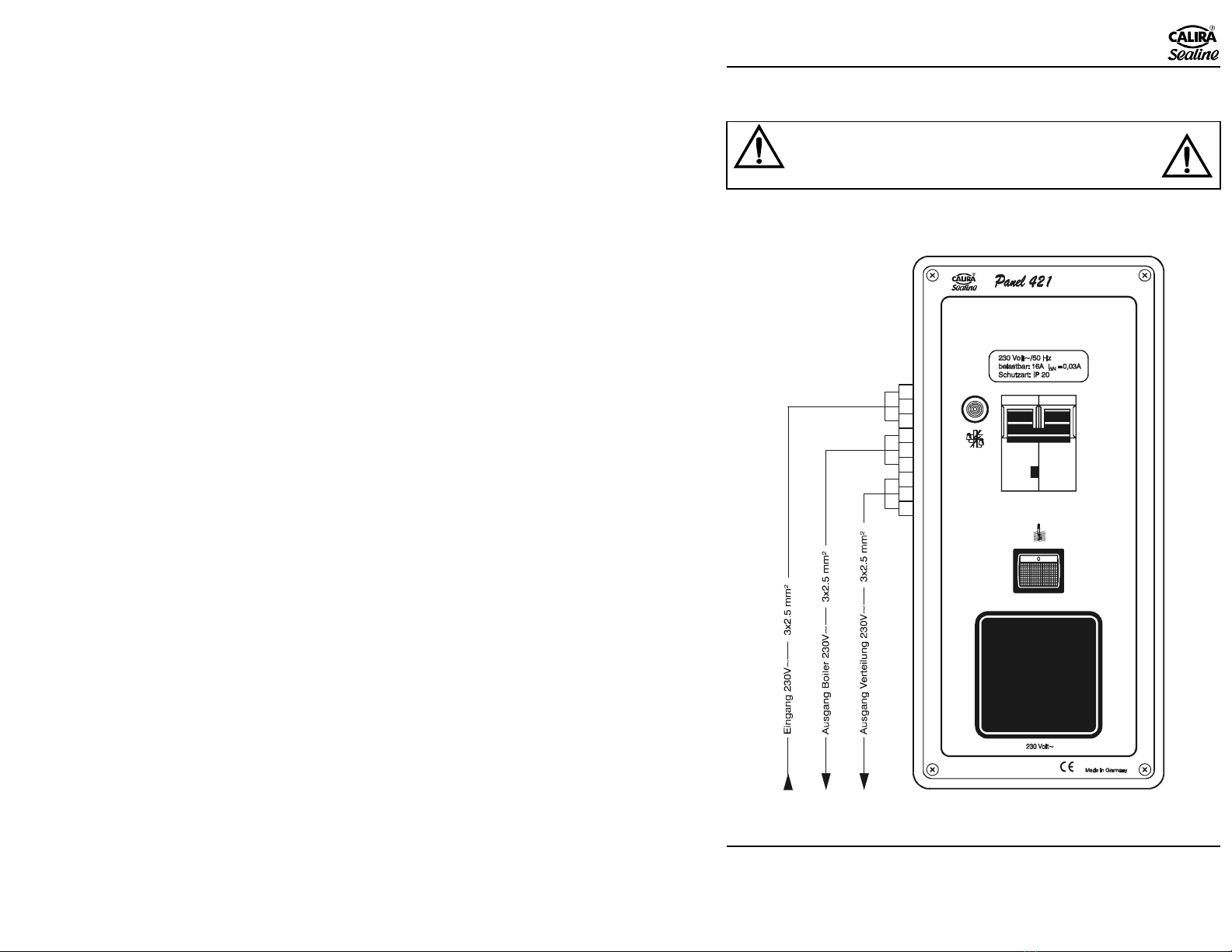
Verwendungszweck
Schalt-/Kontrolltafel zur Absicherung des Bootes, wenn im Hafen oder im
Winterlager an das 230 Volt Wechselspannungsnetz angeschlossen wird. Der
zweipolige Leitungsschutzschalter mit integriertem Fi-Schutzschalter sichert
vor Überlast, Kurzschluss und elektrischen Unfällen. Die Abschaltung des
Netzes erfolgt bei einem Fehlerstrom von 30 mA, bzw. im Überlastfall bei 16
Ampere. Mit beleuchtetem Schalter und separaten Ausgang für einen 230 V
Boiler, 230 V Steckdose mit Deckel, Netzkontrollleuchte.

$%
!
"##
Lerchenfeldstr. 9 87600 Kaufbeuren Tel.: +49(0)8341 / 9764-0 Fax: +49(0)8341 / 67806
4
Beschreibung
1
2
3
4
Bild 1: Panel 421
1 Netzkontrollleuchte
2 Leitungsschutzschalter mit integriertem Fi-Schutzschalter
3 Schalter für 230 V Boiler
4 Schukosteckdose mit Klappdeckel

$%
!
"##
Lerchenfeldstr. 9 87600 Kaufbeuren Tel.: +49(0)8341 / 9764-0 Fax: +49(0)8341 / 67806
5
Technische Daten Panel 421
Frontplatte: Aluminium, titangrau eloxiert
Abmessungen: B 118 x H 250,5 x T110mm
Gewicht: 600g (60N)
Schutzschalter: Leitungsschutzschalter mit integriertem Fehlerstrom-
Schutzschalter 16 A/30 mA
Anschlüsse:
(Reihenklemmen
2,5 mm²)
Eingang 230 V
Ausgang Boiler 230 V
Ausgang Verteilung 230 V
L1 an Klemme 1
N an Klemme 2
PE an Schutzleiterklemme
L1 an Klemme 3
N an Klemme 4
PE an Schutzleiterklemme
L1 an Klemme 5
N an Klemme6
PE an Schutzleiterklemme
Aufbau gemäß: VDE 0100 - 530
Prüfzeichen:
Beipack: Befestigungsschrauben, Betriebsanleitung

$%
!
"##
Lerchenfeldstr. 9 87600 Kaufbeuren Tel.: +49(0)8341 / 9764-0 Fax: +49(0)8341 / 67806
6
Montage
Sicherheitshinweise
Der Anschluss des Geräts an das Versorgungsnetzes muss in
Übereinstimmung mit den jeweils geltenden nationalen
Installationsvorschriften vorgenommen werden.
Die Montage und der Anschluss von elektrischen Geräten muss
grundsätzlich durch geeignetes Fachpersonal erfolgen!
Stellen Sie sicher, dass die Stromzufuhr getrennt ist! Netzstecker ziehen!
Benutzen Sie zum Anschluss des Gerätes nur die mitgelieferten Teile
sowie die vorgeschriebenen Leitungsquerschnitte und Sicherungen!
Benutzen Sie nur geeignetes und einwandfreies Werkzeug.
Schließen Sie das Gerät nur gemäß des mitgelieferten Anschlussplanes an!

$%
!
"##
Lerchenfeldstr. 9 87600 Kaufbeuren Tel.: +49(0)8341 / 9764-0 Fax: +49(0)8341 / 67806
7
Montagedurchbruch
Bringen Sie das Panel 421 an einer vor Feuchtigkeit und Spritzwasser
geschützten Stelle an. Die Maße für den Durchbruch entnehmen Sie bitte der
Skizze (Bild2).
Bild 2: Montagedurchbruch

$%
!
"##
Lerchenfeldstr. 9 87600 Kaufbeuren Tel.: +49(0)8341 / 9764-0 Fax: +49(0)8341 / 67806
8
Handhabung der Käfigzugfederklemmen
Bereiten Sie die Kabel für die 230 Volt Verdrahtung vor. Das Kabelende muss
auf 11 mm abisoliert sein. Aderendhülsen sind nicht erforderlich.
Folgende Abbildungen zeigen die grundsätzliche Handhabung von
Käfigzugfederklemmen, die im Gerät eingebaute Version kann äußerlich
von den Abbildungen abweichen, die grundsätzliche Handhabung bleibt aber
gleich. Die Käfigzugfederklemme kann mit Hilfe eines passenden
Flachschraubendrehers geöffnet werden.
Führen Sie hierzu den Flachschraubendreher in die quadratische Öffnung (Bild
3) und drücken Sie die Käfigzugfederklemme auf (Bild 4). Der Klemmteil der
Feder in der runden Öffnung schwenkt dabei auf.
Führen Sie das Kabel bis zur Isolierung in die Käfigzugfederklemme (runde
Öffnung, Bild 4) ein und ziehen Sie den Flachschraubendreher heraus (Bild 5).
Die Käfigzugfederklemme schließt sich wieder und das Kabel ist sicher
geklemmt.
Wiederholen Sie den Vorgang für alle Anschlüsse.
Achten Sie darauf, dass die Kabelenden fest in den Käfigzugfederklemmen
sitzen!
Käfigzugfederklemme Flachschraubendreher Kabel

$%
!
"##
Lerchenfeldstr. 9 87600 Kaufbeuren Tel.: +49(0)8341 / 9764-0 Fax: +49(0)8341 / 67806
9
Anschluss 230 Volt
!"#
Schließen Sie die 230 Volt Verbraucher und die 230 Volt Zuleitung laut
Anschlussplan (Bild 6) an.
!
"
#
$
%
#
$
%
#
$
%
#
#
#

$%
!
"##
Lerchenfeldstr. 9 87600 Kaufbeuren Tel.: +49(0)8341 / 9764-0 Fax: +49(0)8341 / 67806
10
Die Verkabelung des Schiffes muss den einschlägigen geltenden VDE
Vorschriften sowie den Richtlinien des Germanischen Lloyd entsprechen.
Eingang 230
Volt Leitungsquerschnitt 2,5 mm². Die Leitung ohne
Aderendhülsen an die Käfigzugfederklemme
anschließen. L1 an Klemme 1, N an Klemme 2,
Grün/gelb = Schutzleiter (PE).
Ausgang Boiler
230 Volt Leitungsquerschnitt 2,5 mm². Die Leitung ohne
Aderendhülsen an die Käfigzugfederklemme
anschließen. L1 an Klemme 3, N an Klemme 4,
Grün/gelb = Schutzleiter (PE).
Ausgang
Verteilung 230
Volt
Leitungsquerschnitt 2,5 mm². Die Leitung ohne
Aderendhülsen an die Käfigzugfederklemme
anschließen. L1 an Klemme 5, N an Klemme 6,
Grün/gelb = Schutzleiter (PE).
Prüfen Sie alle Anschlüsse auf sicheren Sitz.
Wartungshinweise
$
"
Das Gerät ist wartungsfrei. Reinigen Sie das Gerät mit einem trockenen,
fusselfreien Tuch.

$%
!
"##
Lerchenfeldstr. 9 87600 Kaufbeuren Tel.: +49(0)8341 / 9764-0 Fax: +49(0)8341 / 67806
11
Instandsetzung
%"
&
Ein defektes Gerät kann nur durch den Hersteller oder dessen Service instand
gesetzt werden. Beachten Sie hier die allgemeinen Sicherheitsbestimmungen.
Service: Trautmann GmbH & Co. KG CALIRA-Apparatebau
Lerchenfeldstr. 9
87600 Kaufbeuren
Servicetelefon: 0190 / 77 03 80 (1,24 Euro/min)
Homepage: www.calira.de,
Garantie
Garantie wird in dem Zeitraum von zwei Jahren ab Kaufdatum gewährt.
Mängel infolge Material- oder Fertigungsfehler werden kostenlos beseitigt
wenn:
Das Gerät dem Hersteller kostenfrei zugesandt wird.
Der Kaufbeleg beiliegt
Das Gerät bestimmungsgemäß behandelt und verwendet wurde.
Keine fremden Ersatzteile eingebaut oder Eingriffe vorgenommen
wurden.
Nicht unter die Garantie fallen Folgekosten und natürliche Abnützung.
Wichtig
Bei Geltendmachung von Ansprüchen aus Garantie und Gewährleistung ist
eine ausführliche Beschreibung des Mangels unerlässlich. Detaillierte Hinweise
erleichtern und beschleunigen die Bearbeitung. Bitte haben Sie Verständnis
dafür, dass wir Sendungen, die uns unfrei zugehen, nicht annehmen können.

&#%
!
"##
Lerchenfeldstr. 9 87600 Kaufbeuren Tel: +49(0)8341 / 9764-0 Fax: +49(0)8341 / 67806
12
'#
&
Table of contents
Safety instructions........................................................13
Purpose........................................................................13
Description...................................................................14
Technical data..............................................................15
Assembly .....................................................................16
Safety instructions........................................................16
Mounting opening........................................................17
Handling of the cage tension spring clamps ................18
230 Volt connection.....................................................19
Maintenance instructions.............................................20
Repairs.........................................................................21
Warranty......................................................................21
Version: 29.04.2005
The right to make technical modifications is reserved.

&#%
!
"##
Lerchenfeldstr. 9 87600 Kaufbeuren Tel: +49(0)8341 / 9764-0 Fax: +49(0)8341 / 67806
13
Please read general safety information carefully!
Attention!
The following important safety instructions must be observed when using
electric devices, as protection against electric shock, injury and fire hazard.
Please read and follow these instructions before using the device.
Setting up
Please ensure that the device is placed securely and cannot fall down or tip
over. Always position cables so that nobody can trip over them. Do not expose
electric devices to rain. Do not operate electric devices in a damp or humid
environment. Do not operate electric devices in the vicinity of flammable
liquids or gases. Place electric devices so that children do not have access to
them.
Protection against electric shock
Only operate devices whose housing and cables are undamaged. Ensure safe
cable positioning. Do not pull cables.
Use
Do not use electric devices other than for the purpose specified by the
manufacturer.
Accessories
Only use accessories and supplementary devices supplied or recommended by
the manufacturer. Using other accessories is hazardous.
Purpose
Switch/control panel for the protection of the boat when it is connected to the
230 Volt AC mains network in harbour or in winter storage. The two-pin
circuit breaker with integrated earth leakage circuit breaker protects from
overload, short-circuit and electrical incidents. The disconnection of the mains
takes place at a leakage current of 30 mA, or in the case of overload at 16
Amps. With illuminated switch and separate output for a 230 V boiler, 230 V
socket with cap, mains indicator lamp.

&#%
!
"##
Lerchenfeldstr. 9 87600 Kaufbeuren Tel: +49(0)8341 / 9764-0 Fax: +49(0)8341 / 67806
14
Description
1
2
3
4
Fig. 1: Panel 421
1 Mains indicator lamp
2 Circuit breaker with integrated earth leakage circuit breaker
3 Switch for 230 V boiler
4 Earth contact socket with cap

&#%
!
"##
Lerchenfeldstr. 9 87600 Kaufbeuren Tel: +49(0)8341 / 9764-0 Fax: +49(0)8341 / 67806
15
Technical data, Panel 421
Front plate: Aluminium, anodised titanium grey
Dimensions: W 118 x H 250.5 x D 110mm
Weight: 600g (60N)
Circuit breaker: Circuit breaker with integrated earth leakage circuit
breaker 16 A/30 mA
Connections:
(Terminal block,
2.5 mm²)
230 V input
Output – boiler, 230 V
Output – distribution, 230 V
L1 to terminal 1
N to terminal 2
PE to protective earth
terminal
L1 to terminal 3
N to terminal 4
PE to protective earth
terminal
L1 to terminal 5
N to terminal 6
PE to protective earth
terminal
Design
according to: VDE 0100 - 530
Test labelling:
Items packed
separately: Fastening screws, operating instructions

&#%
!
"##
Lerchenfeldstr. 9 87600 Kaufbeuren Tel: +49(0)8341 / 9764-0 Fax: +49(0)8341 / 67806
16
Assembly
Safety instructions
(&#'
#
Connecting the device to the power supply must comply with the
applicable national installation regulations.
The assembly and connection of electric devices should always be
carried out by qualified personnel!
Always make sure that the power supply is disconnected! Pull out the
mains plug!
When connecting the device, use only the supplied parts and the specified
cable cross-sections and fuses!
Only use suitable and undamaged tools.
Only connect the device according to the supplied connection diagram!

&#%
!
"##
Lerchenfeldstr. 9 87600 Kaufbeuren Tel: +49(0)8341 / 9764-0 Fax: +49(0)8341 / 67806
17
Mounting opening
Fit the Panel 421 in a position which is protected from moisture and splashed
water. You can find the dimensions for the mounting opening in the sketch
(Fig. 2).
&
'((
Fig. 2: Mounting opening

&#%
!
"##
Lerchenfeldstr. 9 87600 Kaufbeuren Tel: +49(0)8341 / 9764-0 Fax: +49(0)8341 / 67806
18
Handling of the cage tension spring clamps
Prepare the cable for the 230 Volt wiring. Insulation must be removed from 11
mm at the end of the cable. Cable end sleeves are not required.
The following pictures show the basic method of handling cage tension spring
clamps. The version fitted in your device can differ in detail from these
diagrams, but the fundamental method remains the same. The cage tension
spring clamp can be opened with the help of a suitable flat screwdriver.
To do so, insert the flat screwdriver into the lower, square opening (fig. 3) and
open the cage tension spring clamp (fig. 4). The clamping element of the spring
in the round opening opens.
Insert the cable into the cage tension spring clamp up to the isolation (round
opening, fig. 4) and pull out the flat screwdriver (fig. 5). The cage tension
spring clamp closes again and the cable is securely clamped.
Repeat the procedure for all connections.
Make sure that the cable ends sit firmly in the cage tension spring clamps!
Cage tension spring
clamp Flat screwdriver Cable

&#%
!
"##
Lerchenfeldstr. 9 87600 Kaufbeuren Tel: +49(0)8341 / 9764-0 Fax: +49(0)8341 / 67806
19
230 Volt connection
# )
')'#)#
Connect the 230 Volt consumers and the 230 Volt feed cable as shown on the
connection diagram (fig. 6).
)!
"
#
$
%
#
$
%
#
$
%
#
#
#

&#%
!
"##
Lerchenfeldstr. 9 87600 Kaufbeuren Tel: +49(0)8341 / 9764-0 Fax: +49(0)8341 / 67806
20
The installation of cables in the boat must conform with the relevant valid
specifications of the Association of German Electrotechnical Engineers (VDE)
as well as the regulations of German Lloyd.
230 Volt input Cross cable section: 2.5 mm² Connect the cable without
wire terminating sleeves to the cage tension spring
clamp. L1 to terminal 1, N to terminal 2, green/yellow =
PE conductor.
230 Volt boiler
output Cross cable section: 2.5 mm² Connect the cable without
wire terminating sleeves to the cage tension spring
clamp. L1 to terminal 3, N to terminal 4, green/yellow =
PE conductor.
230 Volt
distribution
output
Cross cable section: 2.5 mm² Connect the cable without
wire terminating sleeves to the cage tension spring
clamp. L1 to terminal 5, N to terminal 6, green/yellow =
PE conductor.
Check that all the connections are firm and secure.
Maintenance instructions
(&)'
'
The device is maintenance-free. Clean the device with a dry, lint-free cloth.
Table of contents
Languages:
Popular Cables And Connectors manuals by other brands

Panduit
Panduit TX5e installation instructions

Cleerline
Cleerline SSF-48UHD-AOC-05m troubleshooting guide

Philips
Philips SWA3527 Specifications

Knightsbridge
Knightsbridge JB0011 Installation & maintenance manual

Esterline
Esterline Souriau UTS LC Series Assembly instructions

National Instruments
National Instruments PXI-1031DC installation guide