Calrec Argo S User guide

calrec.com
IP Audio Routing & Mixing System
for Argo S and Argo Q Consoles
ARGO START UP GUIDE V1.0

Calrec Audio Ltd
Nutclough Mill
Hebden Bridge
West Yorkshire
England UK
HX7 8EZ
Tel: +44 (0)1422 842159
Fax: +44 (0)1422 845244
Email: enquiries@calrec.com
calrec.com
No part of this manual may be reproduced
or transmitted in any form or by any means,
electronic or mechanical, including photocopying
and scanning, for any purpose, without the prior
written consent of Calrec Audio Ltd.
Whilst the Company ensures that all details in this
document are correct at the time of publication,
we reserve the right to alter specifications and
equipment without notice. Any changes we make
will be reflected in subsequent issues of this
document. The latest version will be available
upon request. This publication is for International
usage.
Calrec Audio Ltd reserve the right to change
specifications without notice. E & O.E.
The established policy of Calrec Audio
Ltd. is to seek improvements to the design,
specifications and manufacture of all products. It
is not always possible to provide notice outside
the company of the alterations that take place
continually.
Despite considerable effort to produce up to
date information, no literature published by
the company nor any other material that may
be provided should be regarded as an infallible
guide to the specifications available nor does
it constitute an offer for sale of any particular
product.
Argo S, Argo Q, Apollo, Apollo+, Artemis,
Artemis+, Summa, Brio, RP1, Type R, VP2,
Hydra Audio Networking, Bluefin High Density
Signal Processing (HDSP) and ImPulse are trade
marks of Calrec Audio Ltd.
All other trade marks are acknowledged.
© 2023 Calrec Audio Ltd. All Rights Reserved.

IMPULSE
CONTENTS
Start Up Guide 5
Getting Started 6
Checklist 6
1. Power up the Impulse Cores & connect a PC 7
2. Access the basic core configuration 8
Calrec Configure Login Instructions 8
3. Configure the Surface IP Connections 10
4. Connect the Surface to the Impulse Cores 11
Surface Ethernet Switches 11
5. Power up the Surface & create a new show 12
6. Configure Network Switches & Devices 13
7. Access Configure, Connect, Software Updater & Assist 15
8. Update the Core Software to the latest version (Optional) 16
9. Configure AoIP Core Router Ports & AoIP I/O Devices 17
Calrec Connect Login Instructions 18
10. Connecting the Audio Switch and AoIP Devices to the Core 28
11. Understanding Synchronisation 29
12. Examine an example system (Surface+Cores+Devices) 32
13. Navigate the Console & Perform System Tests 34
Surface Panel Overview 34
Layer Navigation 35
Mode Navigation 35
Mode Row Sets 36
Other Argo Panels 37
Basic System Tests 37
DSP Pack Comparison 38
DSP Pack Sizes for Argo S & Argo Q 38
DSP Packs & Multiple Mixers 40
Primary Core - Router Interfaces - Suggested Settings 41
Secondary Core - Router Interfaces - Suggested Settings 42
AoIP Devices - Network Interfaces - Suggested Settings 43
Further Reading - Impulse 44
User Notes 45

4 ImPulse IP Routing & Mixing System

calrec.com
IMPULSE
START UP GUIDE

6 ImPulse IP Audio Routing & Mixing System Start Up Guide
Thank you for choosing Calrec Impulse.
This start up guide will provide the user with all the steps you need to set up the Impulse system as a single studio system, using an
Argo S or Argo Q console surface and various AoIP I/O devices. For links to information about more advanced setups, as well as
other manuals, please refer to the Further Reading section at the back of this start up guide, or contact Calrec Customer Support
(support@calrec.com).
Before you begin, please make sure a PC with Google Chrome installed, running Windows 10 or higher, an ethernet adaptor plus an
ethernet cable, and an internet connection is available to download any update packages you may require.
Note: If Google Chrome is not installed, go to https://www.google.com/chrome/ to download and install it.
Note: The minimum recommended Windows PC specifications are as follows:
- i5 Intel Processor or AMD equivalent
- 4 Gig RAM memory
- Windows 10 - 64bit
- Google Chrome Browser - Version 77 or higher
- Ethernet adaptor for remote connectivity/media network interfaces
- Minimum Display Resolution 1366px X 768px
* Impulse is designed for use with a touch interface where possible. Calrec recommends the use of a 1920x1080 touch screen monitor.
Please also confirm that all the parts listed on the system’s packing list are present, with the correct serial numbers. A print out of the
packing list will have been provided alongside the shipping documentation. The packing list is a document named with the sales order
number and appended with -11 (e.g. 51235-11). If any parts are missing, or sign of damage, please contact Calrec Customer Support.
Important: Please follow this guide to ensure that the system is configured correctly!
Use the checklist below to confirm each step if required.
1. Power up the Impulse cores & connect a PC
2. Access the basic core configuration
3. Configure the Surface IP connections
4. Connect the Surface to the Impulse cores
5. Power up the Surface & Create a new show
6. Configure Network Switches
7. Access Configure, Connect, Software Updater & Assist*
8. Update the Core Software to the latest version (optional)
9. Configure AoIP Router & AoIP Device IP addresses
10. Connect Audio Switches & AoIP Devices to the Core
11. Understand Synchronisation
12. Examine an example system (Surface+Cores+Devices)
13. Navigate the Console & Perform System Tests
If the Checklist is completed then the Argo system is now ready for use
GETTING STARTED
CHECKLIST

7
1. Carefully remove the Impulse core(s) and cable(s) from their packaging. If there are any signs of damage, please contact Calrec
Customer Support and do not continue.
2. In a redundant system, two Impulse cores are used to provide redundancy, one core being the Primary, the other being the
Secondary. These will be identified with labels and when powered the Primary core, will identify itself by lighting its Primary Core
Indicator LED Green, which is located on the front of the Control Module as shown above.
3. To power the core(s), connect the power cable to both PSU inlets on the front of each core and power it on. The Primary core
will boot up with the Primary LED lit and shortly afterwards the Core status LED on each core will flash Green, to show that
the system is running. The Module and Fan OK LEDs should both be lit Green when running.
4. Configure the Ethernet adapter in the PC with an unused IP address such as 172.16.255.99 and Subnet mask 255.255.255.0
Note: Please refer to the PC’s operating instructions, if unsure how to configure its ethernet adapter.
5. Connect the Ethernet adapter to the Setup port on the front of the Primary Impulse Core which by default is the RJ45 connector,
I/F ‘2‘ on the lower front of the Control Module in the Impulse Core.
6. For Redundancy, connect the Impulse cores together, here they are directly linked via a RJ45 Ethernet cable & 2 x SFP interfaces
between the two I/F ‘5’ SFP connections on the lower front of the Control Module on the Primary and Secondary cores.
POWER CONNECTION TO CORE(S) AND PC CONNECTION TO PRIMARY CORE SETUP PORT
1. POWER UP THE IMPULSE CORES & CONNECT A PC

8 ImPulse IP Audio Routing & Mixing System Start Up Guide
2. ACCESS THE BASIC CORE CONFIGURATION
1. To Log in to Configure, open your Web browser e.g. Chrome and browse to the address of the LAN port you are connected to e.g. the
Setup port on the core of the unit which by default is 172.16.255.19 this will open up the Configure Login page shown above.
2. In order to access the Configure Application, the user will need to enter the Username and Password, the user then taps on the
‘Log in’ button and the Configure application then accesses the Home menu as shown at the top of the next page
3. Click on System. The System>General Configuration page will be displayed, as shown at the bottom of the next page.
4. Set the system date & time.
5. You may also set new System and Core names here. These names will be used by the system to identify and announce cores,
as well as in system status messages, so it is important for all the cores you own to be given unique names.
Calrec Configure Login Instructions
From version 1.4 of the Impulse applications and version 2.0 of the Type R applications, security passwords have been put in place,
there are currently two fixed Roles/Accounts available, the normal Operator account and an Engineer account which provides
technician access to extra configuration functionality. For the Operator account, the Username should be entered as ‘Operator’ with
the Password ‘calrec’. Note: both the Username and Password are case sensitive.
CORE CONFIGURE LOGIN PAGE

9
CONFIGURE>HOME PAGE
CONFIGURE>GENERAL CONFIGURATION PAGE

10 ImPulse IP Audio Routing & Mixing System Start Up Guide
3. CONFIGURE THE SURFACE IP CONNECTIONS
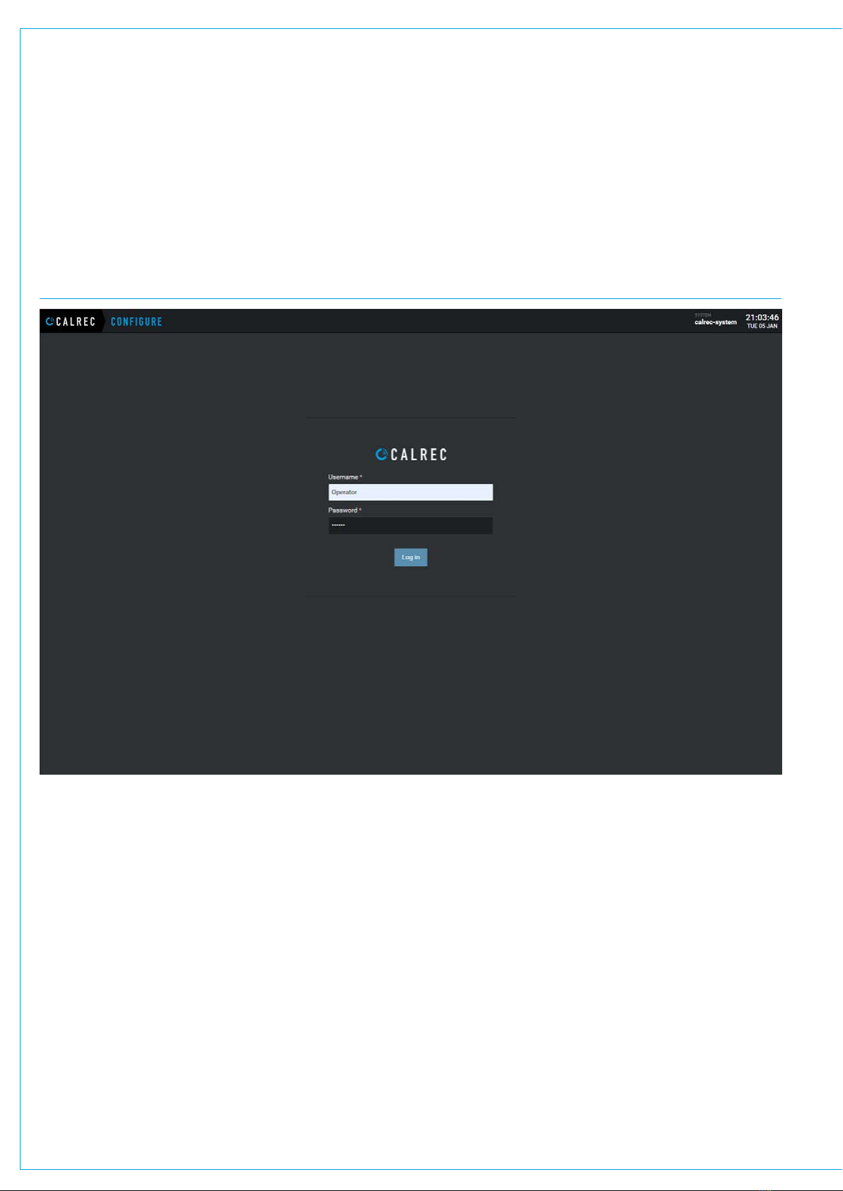
NETWORKS>CONTROL INTERFACES - OVERVIEW
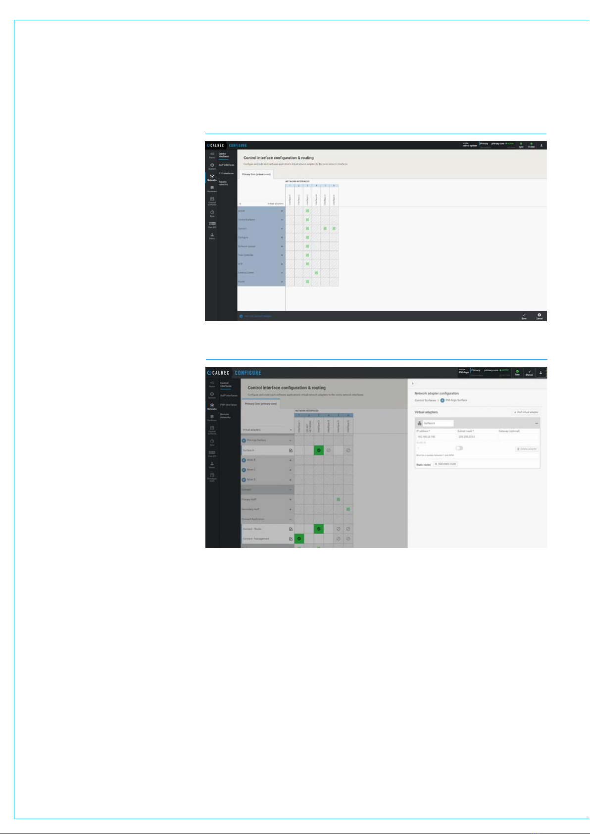
NETWORKS>CONTROL INTERFACES - ROUTE/EDIT VIRTUAL ADAPTERS
Control Interface Routing Screens
The screen shown above right is accessed
from the Networks>Control interfaces
page of the ‘Configure’ application. This
allows the user to display and configure all
the Impulse system software applications
and map their virtual adapters on a routing
matrix, to the six core Network Interfaces
at the bottom of the UN6426 Control
Processor Module labelled ‘1-6’.
The page is arranged in collapsible
accordion-style folders, a folding list of
virtual adapters is shown down the left
side of the screen. Clicking on the ‘+’
key on the Virtual Adapters header will
open all the application containers and
clicking on each application container, will
reveal sub-containers holding the virtual
adapters as shown below right.
Along the top are shown the network
interfaces. Users can click/tap cells in
the matrix grid to route an application’s
virtual network adapter(s) to the physical
interfaces.
When first routed, the selected cell in the
matrix will be highlighted to indicate that
the route is pending. When applied by
pressing the Save button in the footer,
the routes in the matrix will be highlighted
green with an appropriate icon.
To un-route, users can click on the now
routed icon again and apply/save the
change.
The rows to the right of the collapsible
folders in the first column (not to the right
of the virtual adapters), indicate routes
that exist within the folder, both when
collapsed and when opened.
Users can click on any of the configured
virtual adapters or physical network
interface representations in the user
interface, to open a configuration panel
that provides context-specific controls.
Configure the Surface A Route
The Control interface screen shown, has
accessed the Control Surfaces>
PM Argo Surface>Surface A
application container and routed it
to Interface 3 which is the physical
connection SFP port 3on the front of the
Core by the process just described.
This is the external connection from the
core to the Console Surface switches that
were made in the previous step.
It is worth noting that the Console Surface
IP address is set to 192.168.24.190 with
a subnet mask of 255.255.0.0 as shown,
by interrogating the ‘Surface A’ network
adapter configuration shown above.
These settings can be edited, but
this address base is used to reference
the addresses of the surface ethernet
switches that access each section
processor on the same subnet and
subsequently access that section
processors control panels within the
surface to setup the operation of the
Argo Control Surfaces.
The Console Surface secondary
IP address in this example is set to
192.168.25.190 with a subnet mask of
255.255.0.0 as shown, by interrogating
the ‘Surface A’ network adapter on the
secondary core’s configure.

11
4. CONNECT THE SURFACE TO THE IMPULSE CORES
Surface Ethernet Switches
The surface Ethernet switches are the
interfaces between the control surface via
the section processors and the Impulse
processing cores. To provide redundancy,
two surface Ethernet switches are fitted,
primary and secondary. The system will
always attempt to boot and run on the
primary, however if there is a problem
with the primary or its connections, the
secondary will automatically take over.
Like the section processors, the primary
and secondary surface Ethernet switches
are housed in a ventilated enclosure
under the upper surface at the rear of
the console in any two of the console
sections. In the image below they are
shown in section 1 and section 3, when
viewed from the rear, the primary surface
Ethernet switch is usually placed in the
left hand section.
The communication with all the control
panels and displays is via each section
processor. Each section processor is
connected to the primary and secondary
surface Ethernet switches using the
primary and secondary GB Ethernet ports
on each section processor.
The primary surface Ethernet switch
typically has 10 ports and each of
the sections connect to a port. In
the example below ports 1-3 are
connected leaving ports 4-8 available for
connections to sections 4-8 depending
on the size of the surface. Port 9 is
used as the IP link from the primary
surface Ethernet switch to the primary
Impulse core on SFP Port 3 of the
control processor module. See the blue
connections in the image below.
This is repeated using the section
processor's secondary ports to the
secondary surface Ethernet switch and
on to the secondary Impulse Core on SFP
Port 3 of the control processor module.
See the red connections in the image
below.
Note: the 2 Impulse cores are directly
connected between both control
processor modules on SFP port 5’s, for
IP network redundancy. See the yellow
connection in the image below.
Note: if there is a requirement to add
other console sections to this surface
in the form of a Sidecar where say a
separate console on wheels is brought
into the studio, then the connections
from the Ethernet switches in the sidecar
or if no switches the connections directly
from the section processors can be
added to the Primary and Secondary
Ethernet switches rather than routing
the cables back to the Impulse cores
separately. The sidecar may not even be
in the same room as due to the nature of
the IP Network the physical location of
the surfaces are not a factor.
The routing of the core connections to
their applications is made using the
Configure application see
“3. Configure the Surface IP
Connections” on page 10
Note: the rest of the internal console
connections are exactly the same as
defined in the Argo Installation Manual
and are generally pre-configured as per
the works order.
ARGO SURFACE SECTION CONNECTIONS TO IMPULSE CORES VIA BUILT IN ETHERNET SWITCHES

12 ImPulse IP Audio Routing & Mixing System Start Up Guide
5. POWER UP THE SURFACE & CREATE A NEW SHOW
FADER LAYOUT>NEW CHANNEL
Once the connections between the Impulse core and the Argo S or Argo Q console are made and the surface IP connections routed
to the surface application container in the core, the surface can be powered up. It is recommended that the Impulse cores are then
restarted. On restart, the console will boot up with the last loaded show To ensure you are starting from a clean setup, before
beginning configuration it is a good idea to create a new show.Shows contain default settings for the console, including monitor
patching, GPI patching & port labelling. Shows also contain multiple user memories which save normal I/O patching, fader assignment
and path parameter settings. To create a new show, go to the Show area highlighted (top left of the page shown below) and tap
on it. This opens the Shows page and at the bottom is a ‘+New’ button which when pressed allows the user to create a new show.
Choose the Calrec Default as the starting template, enter the details as prompted and click ‘Create’ to load the new, clean show onto
the console. See the image below . The same page allows changes to the show to be saved, as well as other shows to be loaded &
saved, please refer to ‘Argo Operator Manual (926-313).pdf.
The image shown below is accessed from the Fader Layout page which can be used to place Audio paths on to faders. Here the
user has selected a fader position (Layer 1-Fader 1A) and is about to add their first new path. As can be seen from the New Path
dialogue box there are 1122 mono channels available. The user may then begin to configure the mixer with DSP paths, routing etc,
however we would recommend that the user completes the setup first. See ”13. Navigate the Console & Perform System Tests”
on page 34 for further information on Console operation and/or please refer to the Argo Operator Manual (926-313).pdf.
The DSP pack used here
has 1122 channels. Your
Impulse system’s DSP Pack
will be pre-installed to order.
The Impulse Core has a
number of DSP Pack sizes
available, which can be
installed in the DSP Module
and each pack size can be
used in conjunction with any
Argo S or Argo Q surface.
The DSP Pack options
available are shown in a
detailed comparison table at
the end of this guide. See:-
“DSP Pack Comparison”
on page 38
SHOWS>NEW SHOW

13
6. CONFIGURE NETWORK SWITCHES & DEVICES
Impulse and Type R based IP systems use 2 types of COTS switches. The first usage is to provide various VPNs for interfacing
applications via IP, the second is to provide AoIP/AES67 audio streams. Calrec currently recommends and can provide the
following network switches & devices. Note: Other network devices will be added to this list, contact Calrec for further details.
• 491-268: Sonifex AVN-GMCS Grand Master clock. (used for AoIP Synchronisation).
• 491-265: Cisco SG350-10MP 10 port PoE+ switch. (used for Type R Control Panel Interfacing).
• 491-267: Cisco SG350-10 10 port Non PoE switch (used for general interfacing over shared connections).
• 491-270: Artel 1G Quarra PTP Switch. (used for AoIP interfacing with the Core).
• 491-269: Trendnet TPE-115GI - Gigabit PoE+ Injector.(used to add PoE to an ethernet connection).
• 491-329: Cisco CBS350-8T-E-2G switch (used for Argo section processor connections)
If your system was provided with any of these devices, carefully remove each device from its packaging now. If there are any signs
of damage, please contact Calrec Customer Support and do not continue to use the damaged parts.
Important: Some of the above devices may require pre-configuration before installation. Please refer to the guidance for each
device, you have purchased which is available at http://ftp.calrec.com, and access the information in the Type R area of the site
using Account: TypeR & Password: tYoarEdQ before you continue. These switches are small scale devices, general used on
Type R or small Impulse systems, other larger switches, particularly for use with large AoIP systems will be included as they are
introduced.
Cisco Switch Management Settings for multiple connections
Argo S & Argo Q uses switches such as the Cisco CBS350-8T-E-2G switch, as each section processor is connected into it and then
uplinked back to the Impulse Core. The switch needs to have its Energy Detect Mode, Short Reach and 802.3 Energy Efficient
Ethernet Properties disabled. This is carried out in the Port Management>Green Ethernet>Properties page of the switch.
Typically the interface ports may be shared to provide Studio or Management Subnets as described later.
The Cisco switch’s default IP address is 192.168.1.254 and typing this into the address bar of the browser, takes the user to the
switches Log in screen. The default Username is “cisco” and the default password is “cisco”, clicking on the ‘Log in’ button gives
access to the switch’s administration page as shown below:-
At this point, deselect the Energy Detect Mode, Short Reach and 802.3 Energy Efficient Ethernet tick boxes on the Properties page
of the switch as shown, and apply the changes.
Note: the Argo S and Argo Q surface switches do not require POE for the console surface.
CISCO SWITCH GREEN ETHERNET PROPERTIES PAGE

14 ImPulse IP Audio Routing & Mixing System Start Up Guide
Cisco and Artel Switch and Network Configuration for AoIP / AES67 Networks
Below are shown some useful links for AoIP / AES67 network configuration, if using a Cisco SG350 switch for AoIP (which are only
recommended for very small systems) then please refer to the Cisco Auto Configuration guides or Cisco Manual Configuration guides.
There are 3 basic requirements for AES67 based switch operation: - 1. Enabling IGMP Snooping & Querier V2 ,
2. Setting up the DSCP Trust mode and 3. Setting higher DSCP to Queue priorities for PTP clocks EF(46) & Audio AF41 (34) data.
For larger PTP based audio networking using Artel Quarra switches, please refer to the Artel links below:
Artel Quarra PTP switch range
https://www.artel.com/media-transport-products/?swoof=1&product_cat=quarra
Artel Quarra Configuration Guide for AES67
https://www.artel.com/wp-content/uploads/2019/01/Quarra-Configuration-Guide-for-AES67-TC-and-BC-v20-6-24.pdf
* In order to simplify configuration, a text based example configuration file can be uploaded for both the Cisco and Artel Quarra
Switches for use with AoIP/AES67 Network devices. These can be found on the Calrec FTP site at http://ftp.calrec.com as
described earlier and access the information in the Type R area of the site using Account: TypeR & Password: tYoarEdQ
The configuration files both allow the switch to operate in the 192.168.30/24 subnet for the Primary AoIP port address range
and the 192.168.31/24 subnet for the Secondary AoIP port address range, but can be adapted as required.
Artel Switch Management Settings for AoIP / AES67 Networks
The Artel switch is used for AoIP/AES67 Interfacing and needs to have its Port Power Savings Configuration Properties disabled, this
is carried out in the Configuration>Green Ethernet>Port Power Savings page of the switch.
The Artel switch’s default IP address is 192.168.100.100 typing this into the address bar of the browser accesses the Log in screen.
The default Username is “admin” and there is no default Password, clicking on the ‘Sign in’ button gives access to the switch’s
configuration pages. A new Artel switch has its power saving feature disabled by default, but it’s worth checking to ensure this is the
case, if it isn’t then proceed as shown below:-
ARTEL QUARRA SWITCH GREEN ETHERNET PROPERTIES PAGE
Deselect all the tick boxes as shown above on the Port Power Savings page of the switch and click on ‘Save’ to apply the changes.
Then go to Maintenance > Configuration > Save start-up-config and click Save Configuration. This will save the currently running
settings that you have just configured as the switch’s startup configuration, so that it loads whenever it is turned on or rebooted.

15
The Impulse System operates by using a number of application containers to manage the various subsystems, there are 3 or 4 main
applications that are used to provide the user with a graphical user interface via web based browsers, these are :-
Configure application:- this defines how Impulse system core(s) can be configured and partitioned into different mixing surfaces with
varying amounts of DSP processing channels available in different ‘Pack’ sizes.
Connect application:- this defines how the Impulse Core IP Inputs and Outputs are connected to AoIP device interfaces and how the
AoIP streams are managed.
Software Updater application:- this application is used to update all the various software/firmware applications in the system,
including:- Configure, Connect, Software Updater, Twin Controller (redundant links), NTP time protocol management, External Control
for interfacing to Remote production and 3rd party controllers, AoIP Routers & Devices, PTP Synchronisation, DSP processing, MCS,
and Assist.
Assist application:- this defines how a pre-configured Impulse system may be setup and controlled, it includes creating/managing
shows, setting up shows in terms of configuring paths, displaying and controlling the fader surface, saving and loading memories
and patching inputs and outputs to the channels and buses. There are then various sections about parameter access including:-
processing, routing, configuring and controlling the buses & outputs and setting up the monitoring & metering. The show setup and
system settings sections provide configuration tools for both show and system configuration.
Note:- These applications may be accessed via the front-facing Setup port currently set to Interface port 2 on the front of the
Control Processor on the Impulse cores, by navigating to the various applications shown in the IP Addresses access table below.
However the Setup port is not usually connected to a local area network (LAN) and in a studio install scenario, may not therefore
be readily accessible to an operator or engineer’s PC. It is therefore recommended that these applications should be connected
via either a “Management” or a “Studio A” subnet. The “Management” subnet resides in the 172.29/16 address space and
provides access to all applications and services running on the core. The “Studio A” subnet resides in the 172.17/16 address space
and provides access to the Configure & Connect applications, as well as the console control service.
Note:- Impulse is designed to support a Touch Interface if the PC provides this.
To use either subnet configure the PC’s ethernet adaptor as follows:-
• Management - IP address 172.29.1.99, subnet mask 255.255.0.0
• Studio A - IP address 172.17.1.99, subnet mask 255.255.0.0
Note:- The IP addresses for Applications to be made accessible to the Management and Studio subnets
can be setup/modified via Configure in the Networks>Control Interfaces page.
7. ACCESS CONFIGURE, CONNECT, SOFTWARE UPDATER & ASSIST
Application Setup Port
(front of core port 2)
Management subnet
(front of core port
selectable from Configure)
Studio A subnet
(front of core port is
selectable from Configure)
Configure 172.16.255.19 172.29.1.23 172 .17.1. 23
Connect 172.16.255.60 172.29.1.21 172 .17.1.21
Software Updater 172 .16.255.40 172.29.1.22 172 .17.1.22
Assist 172.16.255.25 172.29.1.1 172.17.1.1
To access the Configure, Connect, Software Updater & Assist applications from the various connection points in the system,
type the corresponding IP address shown in the table below into the Google Chrome address bar address bar. From version 1.4 of the
Impulse applications and version 2.0 of the Type R applications, security passwords have been put in place for Configure, Connect and Assist,
there are currently two fixed Roles/Accounts available, the normal Operator account and an Engineer account which provides technician
access to extra configuration functionality. For the Operator account, the Username should be entered as ‘Operator’ with the Password
‘calrec’. Note: both the Username and Password are case sensitive.
IP ADDRESSES FOR ACCESS TO CONFIGURE, CONNECT, SOFTWARE UPDATER & ASSIST USER INTERFACES

16 ImPulse IP Audio Routing & Mixing System Start Up Guide
8. UPDATE THE CORE SOFTWARE TO THE LATEST VERSION (OPTIONAL)
A newer software version for the Impulse core may have been released since the Impulse system left Calrec.
To check the version installed on the system, follow these steps:
1. Open Google Chrome on the connected PC, type 172.29.1.22 into the address bar and press enter to navigate to
the Software Updater landing page as shown below.
Note: If Google Chrome is not installed, navigate to https://www.google.com/chrome/ to download and install it.
2. The installed software version is displayed below the system and core names and above the file upload area.
SOFTWARE UPDATER DISPLAYING INSTALLED SOFTWARE VERSION
Software release packages will be made available on the Calrec FTP server and are displayed with the release version number.
In each package folder there are folders for Base Images, Recovery Images and the release package for the Core itself, which will
have a .calrec extension e.g. argo-release_1.0.4-b55.calrec .
To install a newer software version:
1. Navigate to the Software Updater landing page once again.
2. Drag & drop the update package into the marked area within the browser or click Upload file to open a file explorer
and browse for the file on the system. The updater will automatically upload and unpack the update package.
3. When the file upload is successful, click Install to begin the installation process.
4. The updater will automatically apply all the updates to the core.
5. When completed click Reboot to reboot the core.
Tip: to view more information, click on the Advanced button in the header at any time. This is arranged in collapsible accordion-style
folders showing each areas version number. Clicking on the ‘+’ key will open each drawer on the right side of the window to display
additional detail, without interrupting the update process.
Note: AoIP devices are updated separately using the Connect Application Options-Update Software page.

17
The next stage is to configure the AoIP Router Interfaces in the core and the AoIP Device Interfaces, so that they can be networked
together to allow Audio streams to be passed between the Routers in the Core and the various AoIP I/O Devices, which provide
Audio & GPIO resources. The first step is to setup the Router IP addresses in the core using the Configure application.
To do this, access the Configure Application by opening Google Chrome on the PC, type 172.29.1.23 into the address bar, press enter
to navigate to the Login page, Login and go to the ’Configure’ landing page. Then go to Networks> AoIP Interfaces as shown below.
9. CONFIGURE AOIP CORE ROUTER PORTS & AOIP I/O DEVICES
AoIP Core Router Interfaces
This page can either be accessed from
the Networks Menu and appears as
shown above right. Each Impulse core
can accommodate up to 4 router modules
and each module has 8 x 1 Gbps Ethernet
ports which are arranged as 4 pairs
to provide seamless packet switching
redundancy.
Each port is capable of passing 512
channels of audio in each direction,
however there are communications
overheads including mic gain control and
GPIO switching functions amongst others
so Calrec suggests a practical limit of
256 bi-directional channels per router
connection.
The page shown below right provides
controls to view and configure the
following for each of the router ports:-
IP address
Subnet mask
Gateway (optional)
Note: the IP address and Subnet
mask must be set with valid values.
The Gateway is optional.
The current connectivity status of each
port is displayed as either Connected
or Disconnected. The images to the
right show that just the 1A router port is
currently connected, for seamless packet
switching redundancy the 1B port should
also be connected.
The MAC address of each port is also
displayed (but is not editable). The
speed of each port is displayed (in Gbps).
For Impulse all ports operate at 1Gbps.
Users can edit these by clicking on the
pencil icon for each port to open an
‘Edit Port Configuration’ dialogue box.
CONFIGURE>NETWORKS>AOIP CORE INTERFACES
CONFIGURE>NETWORKS>AOIP CORE INTERFACES-EDIT
Once the IP address, Subnet mask and
optional Gateway has been edited, the
user can click on the ‘Save’ button to
update the port configuration and return
to the AoIP interfaces page.
The page entries are designed to be
‘folded-up’ in order to show all the AoIP
router interfaces that are be attached.
The tables at the end of this document
offers suggested settings for the Primary
and Secondary Router Interfaces
of each of the Impulse Cores. See:-
“Primary Core - Router Interfaces -
Suggested Settings” on page 41 &
“Secondary Core - Router Interfaces
- Suggested Settings” on page 42
Also refer to the Impulse Configure
Application Guide (926-290).pdf for
further information.

18 ImPulse IP Audio Routing & Mixing System Start Up Guide
Once the AoIP Routers are setup the next step is to setup the AoIP I/O Devices.
To do this, access the Connect Application as shown below:-
Calrec Connect Login Instructions
1. Open your Web browser e.g. Chrome and browse to the address of the LAN port you are connected to e.g 172.29.1.21
This will launch Connect, which opens the Connect Login page shown below.
CALREC CONNECT LOGIN PAGE
2. In order to access the Connect Application, the user will need to enter the Username and Password, the user then taps on the
‘Log in’ button and the Connect application then accesses the Devices menu as shown at the top of the next page.

19
AoIP I/O Core and Device Interfaces
This page is accessed from the Devices
Menu and appears as shown above right.
Here we are showing two items:-
‘calrec-system’ which is the chosen
name for the Impulse core & ‘Combo 31’,
which is a Type R Combo AoIP device.
The interface information for ‘Combo 31’
is shown middle right.
Each row on the interface sub-page table
represents an AoIP interface connection,
on a Type R AoIP device there is 1 set of
AoIP interfaces having both a Primary and
Secondary connection.
The columns in the table provide
information about:-
- AoIP interface’s status:- Green is active,
Red is not active.
- AoIP interface name.
- AoIP interface IP address.
- Type of IP address, i.e. if the IP address
type is static (manually configured) or
DHCP (dynamically allocated).
- AoIP interface’s MAC address.
- AoIP interface connection speed.
- AoIP interface TX use percentage.
- AoIP interface RX use percentage.
Configure IP Settings for IO Boxes
Clicking on any of the AoIP interface
rows on the Core or AoIP devices, opens
a dialogue box. The IP settings for the
selected AoIP interface are shown below
right for the AoIP 1: Pri interface for
‘Combo 31’.
The user sets up the IP address by
modifying the following 4 fields:-
Mode:- Type of IP address, i.e. if the
IP address type is a static manually
configured address or if it is a DHCP
dynamically allocated address.
IP Address:- This example shows that the
device & router are in the same subnet.
Subnet Mask:- Typically set to
255.255.255.0 or /24.
Gateway:- Optional.
CONNECT>DEVICES>AOIP CORE INTERFACES
CONNECT>DEVICES>AOIP I/O DEVICE INTERFACES-EDIT IP ADDRESS
CONNECT>DEVICES >AOIP I/O DEVICE INTERFACES

20 ImPulse IP Audio Routing & Mixing System Start Up Guide
Setup AoIP Core Transmitters
and AoIP Device Receivers for
Outputs configuration
Now the AoIP Core Router & AoIP Device
interfaces are setup, the next step is to
create transmitter and receiver streams
for them using the ‘Connect‘ application.
AoIP Core Transmitters
The User configures AoIP transmitters in
the core, the page shown above right is
accessed from the Devices menu when
the ‘calrec-system’ device’s ‘Transmitters’
tab is selected, it is used to add/remove
and configure transmitters.
The number of available transmitters
shown here for the Impulse Core is 256,
this is based on one router connected
having 4 AoIP interface Pri/Sec sets on
each router, each of which carries 256
channels i.e. a total of 2048 channels
with each stream carrying 8 channels,
thus providing 2048/8=256 available
transmitters.
Each row on the transmitters sub-page
table represents a transmitter.
The columns in the table provide the
following information about:-
- Transmitter name e.g. Imp TX1.
- Transmitter interface e.g. AoIP 1:Pri.
- Type of transmitter, normally defined as
a Multicast one to many type rather that
a Unicast one to one type.
- Number of channels in each transmitter
e.g. 8.
- Codec used e.g. L24.
- Packet time e.g. 125us.
-Sample Rate e.g. 48000Hz.
Transmitter Settings - Core
When the user selects one of the
available transmitters or clicks on ‘Add
Transmitter’ at the bottom of the page, a
dialogue box appears, allowing the user to
configure the transmitter as shown below
right.
It shows information for VIEWING ONLY
and also settings that can be ADJUSTED.
Source Device: This is set on the
summary page using ‘Connect’.
CONNECT>DEVICES>AOIP CORE TRANSMITTERS
CONNECT>DEVICES>AOIP CORE TRANSMITTERS- ADD/EDIT/DELETE
Transmitter Name: The user can edit
the transmitter name by clicking in the
Name field and saving it.
No of Channels in the Transmitter:
The maximum number of channels that
can exist in a stream is 80, however a
channel count of either 8 or 16 channels
is more common for transmitting groups
of related channels to a destination.
Please refer to the Connect Application
Guide (926-292).pdf for further
information beyond this simple setup of a
transmitter, including Advanced Settings.
This manual suits for next models
1
Table of contents
Other Calrec Dj Equipment manuals
Popular Dj Equipment manuals by other brands

SnowMasters Special Effects
SnowMasters Special Effects BM-500 user manual

ELAN Lighting
ELAN Lighting PSD-312 user manual

Squareled
Squareled Aura Bar & Matrix Beam Light 100 manual

Velleman
Velleman VDPLW2300N user manual

ETC
ETC Source Four LED Series quick guide

Equinox Systems
Equinox Systems HYPE user manual