1. Place four mounting brackets as close as possible to vent corners, with the slotted side
down towards the RV’s roof. Do not attach yet – leave them sitting.
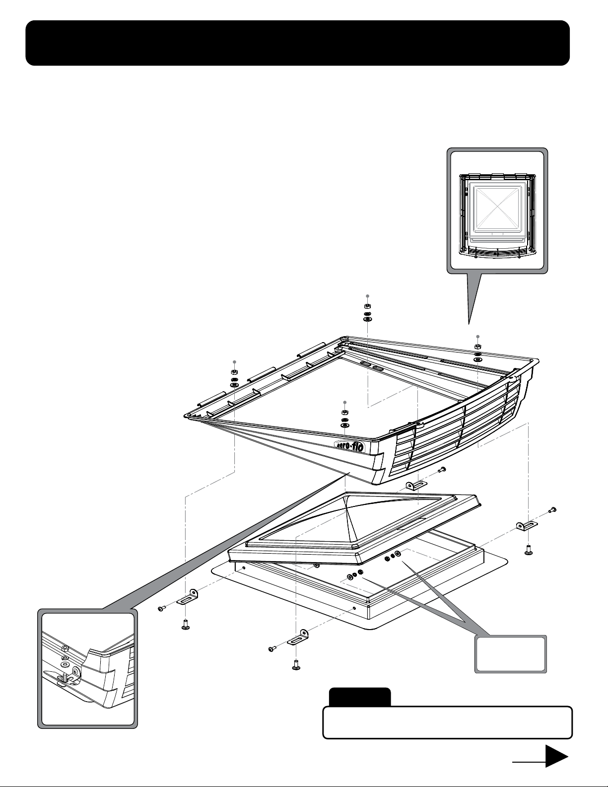
2. Gently lower and center Aero-Flo™ base over vent and brackets. Louvers on
Aero-Flo™ (big end) face rear of vehicle.
3. Position so that slots on brackets and Aero-Flo™ base are lined up.
Carriage bolt must be able to pass through both. Adjust as necessary.
4. Once brackets are properly located, carefully lift Aero-Flo™ base off vent. Try not to let
brackets move. Hold each bracket against side of vent and use fine tip marker to make
vertical lines on vent frame on each side of all four brackets. Remove brackets.
5. Place one carriage bolt through slot on bracket and place bracket between lines marked
in step 4. Head of carriage bolt will be resting on RV roof (or caulking around vent).
Hold bracket against side of vent frame and mark hole location with marker.
Repeat for other three brackets.
6. IMPORTANT! DO NOT PROCEED until you verify holes to be
drilled will, or will not, be visible from the inside of the
vent. Then follow the instructions below:
Holes are NOT visible from inside:
Drill holes with 5/32" drill bit.
Attach brackets to vent frame
(with carriage bolts placed in
slots) using #10 Self tapping
screws. Note: Be careful not
to drill into wires on a high
powered fan.
Holes are visible from inside:
Drill holes with 7/32" drill bit. Attach
brackets to vent frame (with carriage
bolts placed in slots) using #10
Machine screws, flat washers,
lock washers and nuts.
7. Fasten Aero-Flo™ base to each
bracket with 1/4" carriage bolt,
flat washer, lock washer and
nut. A gap between the
Aero-Flo™ base and
roof is normal.
INSTALL BASE FIRST
1
2
THEN ATTACH TOP.
• Kneel behind the louvered (big)
end of the Aero-Flo™.
• Place the front hinge rods on the
top under the hinge lips on the
front of the base.
• Make sure 2 lips on top straddle
lip on base.
•Tighten both rear locking screws until
secure. Do not over tighten.
•The Aero-Flo™ is constructed of a
high-tensile resin that allows for a
certain amount of flexibility – it is
extremely important to make sure
hinge rods and lips are fully engaged
(seated). If not, gently move into place.
• Installation or cleaning
• At the start and end of each camping season
• Whenever top cover has been opened
Warning – always check for proper assembly after:
STEP
STEP
WHEN ATTACHING THE AERO-FLO™ TOP, IT IS VERY IMPORTANT TO FOLLOW THESE INSTRUCTIONS IN ORDER .
Carriage
bolt
Warning:
DO NOT OVERTIGHTEN – this will deform
plastic around slots.
NEXT
Overhead View
#10 Machine
screw or
#10 Self
Tapping screw
Use with #10
Machine screws
only.