General
The camera system is based around two main components, the camera head unit and the interface unit.
It is possible to use the camera head unit independently, but this requires a 6-12v DC supply and the
video output provided is Y, Pr, Pb. If you need to operate in this way please contact Camera Corps for
wiring details.
In its simplest form the camera and interface unit together provide a system that simply takes in DC power
and provides 3 x SD/HD-SDI outputs. In this mode the camera will be in wide angle, auto focus and auto
tracking white balance mode of operation.
With the addition of the Universal RCP full remote control is provided over long distances using just a Cat
5 or audio cable. This control includes all the usual camera control functions allowing complete matching
to other makes and types of broadcast camera. Presetting of Zoom and Focus is also provided from the
RCP panel.
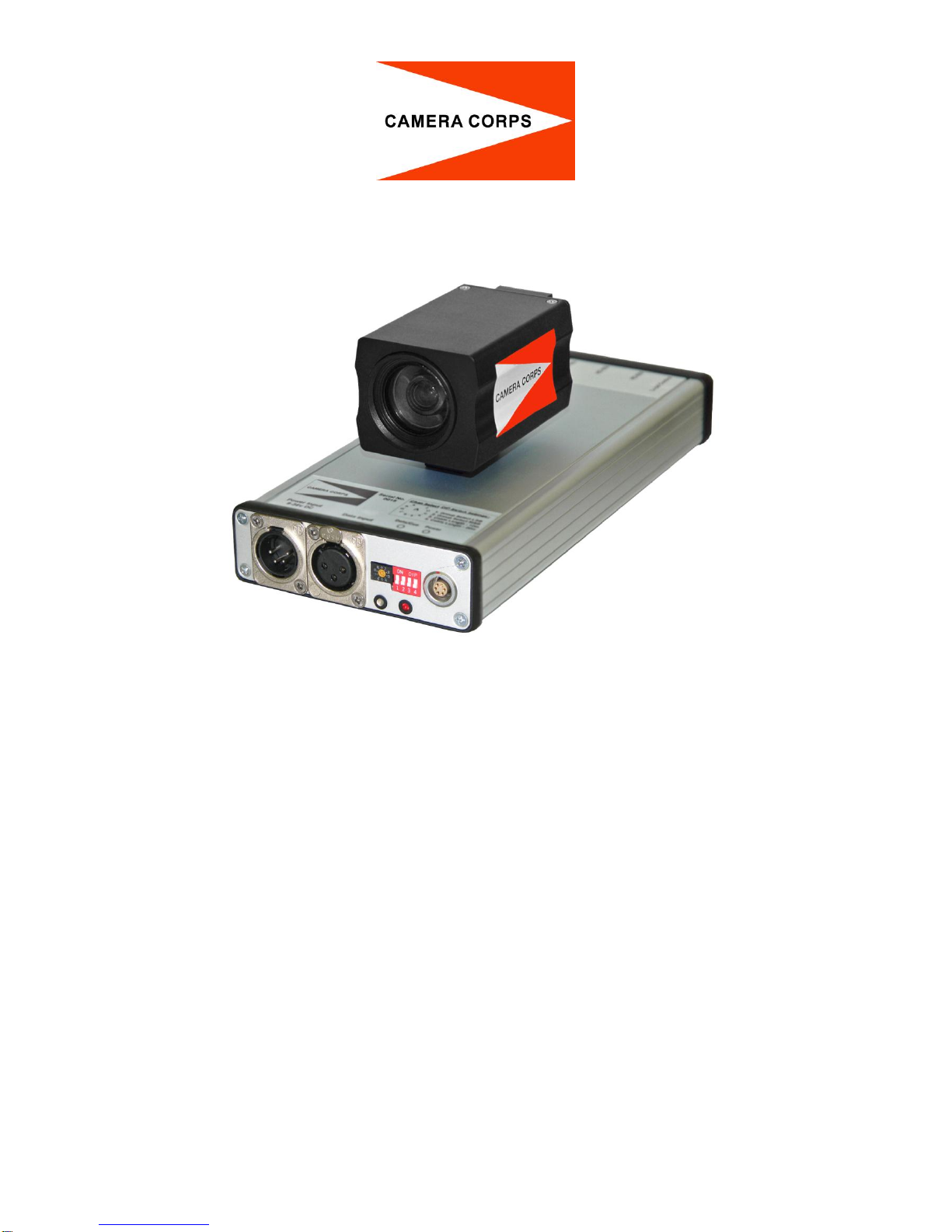
Camera Head Unit
The camera head unit is sealed against moisture and dirt ingress although should not be considered
‘submersible’. The fitting is a standard ¼ inch thread.
Interface Unit
The interface unit takes power from a standard XLR4 socket and will accept any voltage from 9 to 18v DC.
The data input on the XLR3 is for data which conforms to the standard Camera Corps data system. This is
in the form of a balanced audio signal which can be sent over virtually unlimited distances down a normal
microphone cable or CAT5. No DC continuity is necessary.
The rotary switch together with the left hand two DIP switches allow selection of up to 32 data ID’s.
The right hand two DIP switches are used to select the length of the camera cable. One switch provides
equalisation for 10m of cable and the other for 20m. Both switches on together will provide compensation
for 30m of camera cable.
Note that the camera can be plugged in and out of the RCP panel while power is on without damage.
However, if the camera is plugged into an interface unit which is already switched on, then initial data
which is sent to the camera during switch on will be missed and the camera may be in a non standard
condition.
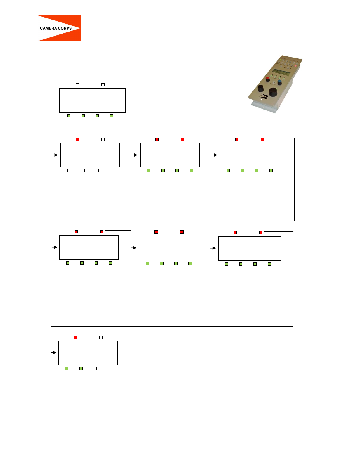
Changing the Camera Format
The SD-HD MiniZoom can operate in both SD and HD modes at 50hz or 59.94 hz. Both 720p and 1080i
formats are available in HD. In PAL or NTSC, SD modes both 4x3 and 16x9 aspect ratios can be
selected.
The required format is set using the rotary channel select switch together with the four front panel DIP
switches. The following procedure must be followed to set or change the format:-
(Note that the SD-HD MiniZoom camera must be connected to the interface unit during this procedure)
Remove power from the Interface Unit.
Set the rotary channel select switch to channel 0.
Set the four DIP switches to the required format using the table below.
Apply power to the Interface Unit and wait until the LED below the channel select switch flashes
RED/GREEN. (Approx 10secs).