CAMERA LINK PHRONTIER PHIRE PHR-68-M025 User manual

PHIRE
Fiber Adapters For Camera Link
User Manual
Revision 4
PHx-xx-Mxxx, PHx-xx-Sxx
PHR-6x-M025-E
TM
D-A-CH
Laser 2000 GmbH
82234 Wessling
Tel. +49 8153 405-0
info@laser2000.de
www.laser2000.de
FRANCE – Telecom
Laser 2000 SAS
78860 St-N. l. Bretèche
Tel. +33 1 30 80 00 60
info@laser2000.fr
www.laser2000.fr
FRANCE – Photonic
Laser 2000 SAS
33600 Pessac
Tel. +33 5 57 10 92 80
info@laser2000.fr
www.laser2000.fr
IBERIA
Laser 2000 SAS
28034 Madrid
Tel. +34 617 308 236
info@laser2000.es
www.laser2000.es
NORDICS
Laser 2000 GmbH
112 51 Stockholm
Tel. +46 8 555 36 235
info@laser2000.se
www.laser2000.se

Phrontier Technologies PHIRE User Manual V4
2
TABLE OF CONTENTS
1. Introduction ........................................................................................................................... 3
2. Available Models...................................................................................................................3
2.1. Two fiber models with multimode fibers.......................................................................... 3
2.2. Two fiber models with single mode fibers ....................................................................... 3
2.3. Single fiber models (PHIRE-S series)............................................................................. 4
3. Packing List...........................................................................................................................4
4. Installation............................................................................................................................. 4
5. Functionality.......................................................................................................................... 5
5.1. DC Power Input Port....................................................................................................... 6
5.2. Camera Link Port & PoCL compatibility.......................................................................... 6
5.3. LED Status Indicators..................................................................................................... 7
5.4. Optical I/O Port............................................................................................................... 7
5.5. Optical Fiber Cable......................................................................................................... 8
6. Technical Specifications........................................................................................................ 9
6.1. General Specification ..................................................................................................... 9
6.2. Camera Link Interface.................................................................................................... 9
6.2.1. Two fiber models................................................................................................. 9
6.2.2. Single fiber models (PHIRE-S series) ................................................................. 9
6.3. Optical Interface............................................................................................................10
6.3.1. Two fiber models................................................................................................10
6.3.2. Single fiber models (PHIRE-S series) ................................................................10
6.4. Mechanical Dimensions.................................................................................................10
7. Trouble Shooting:................................................................................................................ 11
8. Product Safety and Regulatory Compliance: ....................................................................... 12
8.1. Product Safety:..............................................................................................................12
8.2. Regulatory Compliance: ................................................................................................12
9. Contact Us: ......................................................................................................................... 13
FIGURES
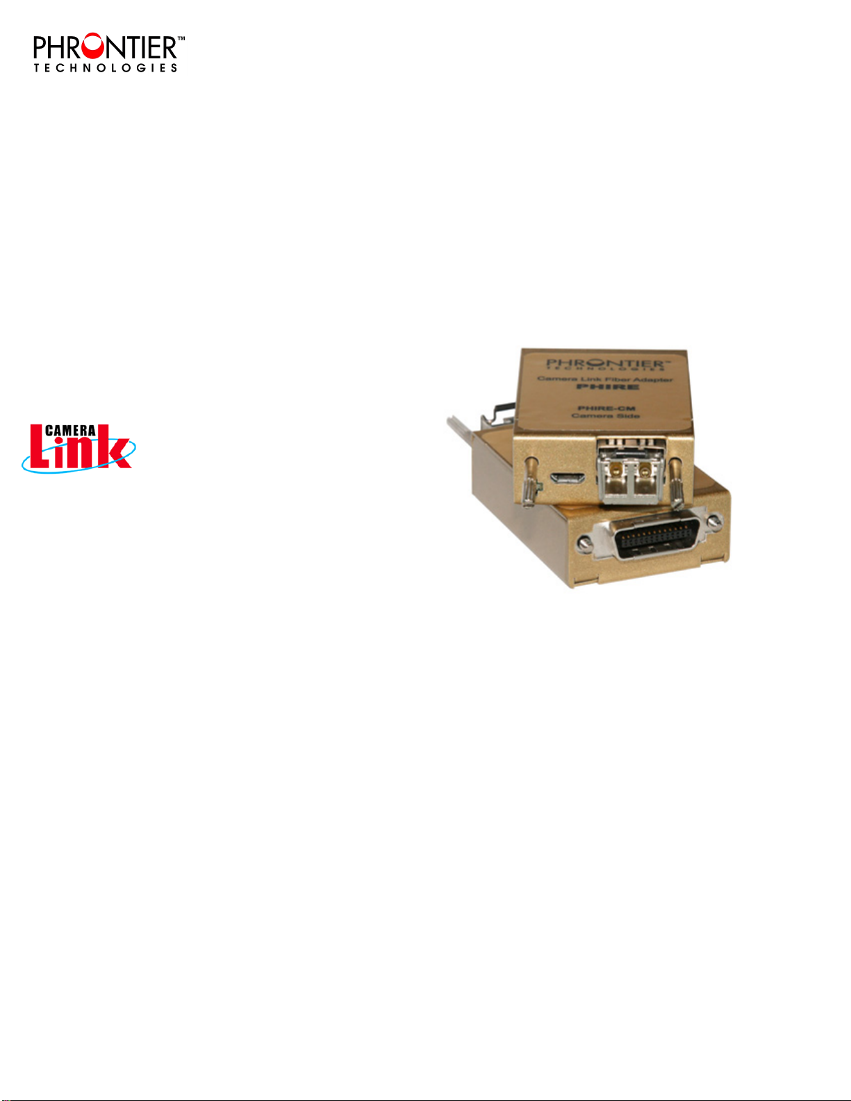
Figure 1 PHIRETM System Diagram ........................................................................................... 5
Figure 2 Electrical Connection of DC Input Connector (Front View)........................................... 6
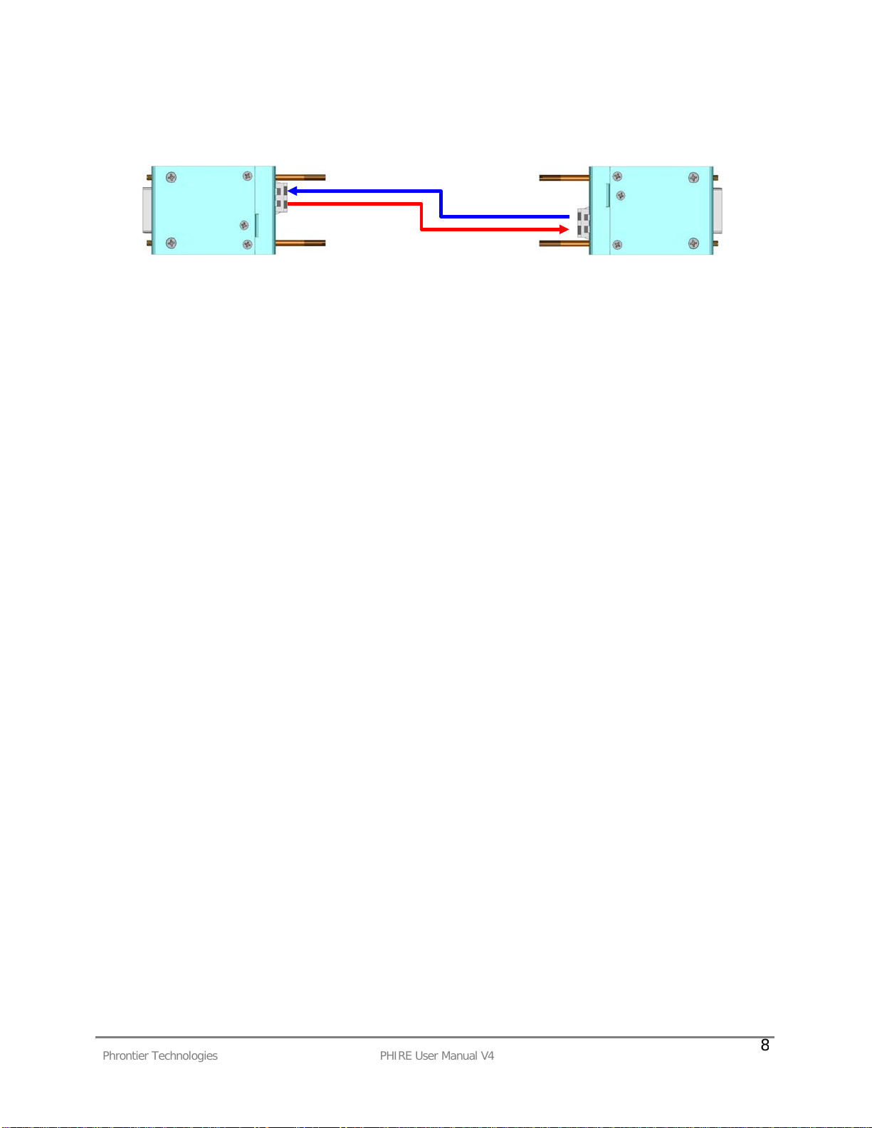
Figure 3 Optical fiber connection................................................................................................ 8
TABLES
Table 1 Installation and Power up Steps for the PHIRE System................................................. 5
Table 2 PoCL features and pin assignment on MDR26 plug...................................................... 7
Table 3 LED Functionality Descriptions...................................................................................... 7
Table 4 Trouble Shooting Procedures.......................................................................................12
D-A-CH
Laser 2000 GmbH
82234 Wessling
Tel. +49 8153 405-0
info@laser2000.de
www.laser2000.de
FRANCE – Telecom
Laser 2000 SAS
78860 St-N. l. Bretèche
Tel. +33 1 30 80 00 60
info@laser2000.fr
www.laser2000.fr
FRANCE – Photonic
Laser 2000 SAS
33600 Pessac
Tel. +33 5 57 10 92 80
info@laser2000.fr
www.laser2000.fr
IBERIA
Laser 2000 SAS
28034 Madrid
Tel. +34 617 308 236
info@laser2000.es
www.laser2000.es
NORDICS
Laser 2000 GmbH
112 51 Stockholm
Tel. +46 8 555 36 235
info@laser2000.se
www.laser2000.se

Phrontier Technologies PHIRE User Manual V4
3
1. Introduction
Camera LinkTM is a high-speed camera/frame grabber interface designed for high performance
vision applications. However, normal copper links can only deliver the signal for 10 meters or
shorter. PHIRE is designed to directly plug into the cameras/frame grabbers to covert the
electrical signals into optical signals, which can be transported by optical fibers for over 80km
without any kind of repeaters or amplifiers in between.
KEY FEATURES OF THE PHIRE™ SYSTEM:
- Fully supports Camera LinkTM base configuration
- Zero loss and transparent transport – no changes required for camera and/or frame grabber
- Supports up to 24 bit (3 taps) image data at max. of 85MHz
- LC duplex fiber interface
- Two LED indicators for system status
- Snap lock power connector with audible click when fully mated
- Single 5V~24V DC power supply on both ends (12V recommended)
- Included international AC/DC adapters accept 100~240V AC power
- 0~60C operating temperature (-20~70C available)
- Maximum 2.4 W power consumption
- PoCL compatible while using 12V power supply
- Eight standard models for different applications (customized options available)
2. Available Models
2.1. Two fiber models with multimode fibers
Model PHR-68-M025 PHR-85-M025 PHR-85-M020
Image Data a24 bit 16 bit 24 bit
Pixel Clock 68 MHz 85 MHz 85 MHz
Distance
OM3 fiber 600 m (1800 ft) 600 m (1800 ft) 550 m (1650 ft)
OM2 fiber 250 m (900 ft) 250 m (900 ft) 200 m (700 ft)
OM1 fiber 150 m (450 ft) 150 m (450 ft) 100 m (300 ft)
(PHR-6x-M025-E for -20~70deg C operating temperature)
2.2. Two fiber models with single mode fibers
Model PHR-68-S10 PHR-85-S10 PHR-85-S07
Image Data a 24 bit 16 bit 24 bit
Pixel Clock 68 MHz 85 MHz 85 MHz
Distance 10 km (6.25 miles) 10 km (6.25 miles) 7 km (4.38 miles)
aCamera Link interface bit assignment defined in Camera Link standard annex C
CL Port
A0
A1
A2
A3
A4
A5
A6
A7
B0
B1
B2
B3
B4
B5
B6
B7
C0
C1
C2
C3
C4
C5
C6
C7
16-bit
√
√
√
√
√
√
√
√
√
√
√
√
√
√
√
√
X
X
X
X
X
X
X
X
24-bit
√
√
√
√
√
√
√
√
√
√
√
√
√
√
√
√
√
√
√
√
√
√
√
√
D-A-CH
Laser 2000 GmbH
82234 Wessling
Tel. +49 8153 405-0
info@laser2000.de
www.laser2000.de
FRANCE – Telecom
Laser 2000 SAS
78860 St-N. l. Bretèche
Tel. +33 1 30 80 00 60
info@laser2000.fr
www.laser2000.fr
FRANCE – Photonic
Laser 2000 SAS
33600 Pessac
Tel. +33 5 57 10 92 80
info@laser2000.fr
www.laser2000.fr
IBERIA
Laser 2000 SAS
28034 Madrid
Tel. +34 617 308 236
info@laser2000.es
www.laser2000.es
NORDICS
Laser 2000 GmbH
112 51 Stockholm
Tel. +46 8 555 36 235
info@laser2000.se
www.laser2000.se

Phrontier Technologies PHIRE User Manual V4
4
2.3. Single fiber models (PHIRE-S series)
Model b PHx-68-
M50 PHx-85-
M50 PHx-85-
M25 PHx-68-
S10 PHx-85-
S10 PHx-85-
S07
Image Data a 24 bit 16 bit 24 bit 24 bit 16 bit 24 bit
Pixel Clock 68 MHz 85 MHz 85MHz 68 MHz 85 MHz 85 MHz
Distance c 500 m 500 m 250m 10 km 10 km 5 km
bx = L for LC connectors, X= S for SC connectors.
cDistances are estimated with 50/125 µm OM2 multi-mode fiber and 9/125 µm single-mode fiber.
3. Packing List
Each standard package of the PHIRE system comes with the following items:
Items/Description Quantity Included
PHIRE-CM module x1
PHIRE-FG module x1
International wall mount AC/DC power adapter
(12V DC out) with micro USB type B plug x2
4. Installation
Warning:
Electrical grounding is important. Improper grounding may cause damage to the PHIRE system
and/or your own system. PHIRE CM module share the same signal ground with the camera and
should be powered from the same power source as the camera. PHIRE FG module share the
same signal ground with the frame grabber and should be powered from the same power
source as the frame grabber.
Users would need the following items for proper installation.
To ensure safe and successful installation of the PHIRE™ system into your application, we
STRONGLY RECOMMEND that you power off all related electronic devices, including the
camera, frame grabber and PHIRE-CM/PHIRE-FG modules, BEFORE performing the following
installation. Otherwise, system malfunction may happen and DAMAGE may be caused to the
PHIRE™ system and/or your own system.
1. Camera Link compatible camera X 1
2. Camera Link compatible frame grabber X 1
3. Correct type of optical fiber cable (single mode or multi-mode, corresponding to the
purchased PHIRE models) with correct connectors at both ends X 1
4. PHIRE-CM module X 1
5. PHIRE-FG module X 1
6. 5 ~ 24V DC power supply with correct connector plugs (two AC/DC adapters are
included in the package) X 2
D-A-CH
Laser 2000 GmbH
82234 Wessling
Tel. +49 8153 405-0
info@laser2000.de
www.laser2000.de
FRANCE – Telecom
Laser 2000 SAS
78860 St-N. l. Bretèche
Tel. +33 1 30 80 00 60
info@laser2000.fr
www.laser2000.fr
FRANCE – Photonic
Laser 2000 SAS
33600 Pessac
Tel. +33 5 57 10 92 80
info@laser2000.fr
www.laser2000.fr
IBERIA
Laser 2000 SAS
28034 Madrid
Tel. +34 617 308 236
info@laser2000.es
www.laser2000.es
NORDICS
Laser 2000 GmbH
112 51 Stockholm
Tel. +46 8 555 36 235
info@laser2000.se
www.laser2000.se

Phrontier Technologies PHIRE User Manual V4
5
Table 1 Installation and Power up Steps for the PHIRE System
5. Functionality
The PHIRE™ system consists of two adapter modules, PHIRE-CM on the camera side and
PHIRE-FG on the frame grabber (or PC) side. The block diagram of the PHIRE system is shown
in Figure 1. All electrical signals on the left-hand side of PHIRE-CM have a one-to-one
correspondence with the ones on the right-hand side of PHIRE-FG. Each adapter module
converts its input electrical signals into a single optical signal and sends it to the other adapter
module. It also receives a single optical signal from the other adapter module and converts it
back into multiple output electrical signals. With the PHIRE™ system, the signal transmission
distance between the camera and the frame grabber can be extended up to 80 kilometers
without any repeaters or amplifiers in between. Most importantly, the PHIRE™ system is totally
transparent to the camera and the frame grabber, which means seamless and easy system
integration. The functionality of the PHIRE system is described in details below.
Figure 1 PHIRETM System Diagram
STEP INSTALLATION STEPS
1 Power off camera and frame grabber
2 Plug PHIRE-CM module to the camera and secure the module with thumb screws
3 Plug PHIRE-FG module to the frame grabber and secure the module with thumb
screws
4 Take off the caps on LC connectors at both ends of optical fiber cable.
Take off the caps on the LC fiber ports of PHIRE-CM and PHIRE-FG.
Plug LC fiber cable to both PHIRE-CM and PHIRE-
FG. Users should hear a click
sound, which indicates a successful mate.
5 Connect power plugs to PHIRE-CM and PHIRE-
FG. Users should hear a click
sound, which indicates a successful mate.
STEP POWER UP STEPS
6 Power up Camera
7 Power up the equipment (e.g., PC) where the frame grabber is installed
8 Power up PHIRE-FG by plugging AC/DC adapter into the AC power source
9 Power up PHIRE-CM by plugging AC/DC adapter into the AC power source
Camera Link
FVAL/LVAL/DVAL/SP
IMAGE DATA (24b)
PIXEL CLOCK
CC1 – CC4
SERIAL PORT
Fiber optics I/F
Camera Link
FVAL/LVAL/DVAL/SP
IMAGE DATA (24b)
PIXEL CLOCK
CC1 – CC4
SERIAL PORT
Fiber optics I/F
PHIRE-CM
PHIRE-FG
D-A-CH
Laser 2000 GmbH
82234 Wessling
Tel. +49 8153 405-0
info@laser2000.de
www.laser2000.de
FRANCE – Telecom
Laser 2000 SAS
78860 St-N. l. Bretèche
Tel. +33 1 30 80 00 60
info@laser2000.fr
www.laser2000.fr
FRANCE – Photonic
Laser 2000 SAS
33600 Pessac
Tel. +33 5 57 10 92 80
info@laser2000.fr
www.laser2000.fr
IBERIA
Laser 2000 SAS
28034 Madrid
Tel. +34 617 308 236
info@laser2000.es
www.laser2000.es
NORDICS
Laser 2000 GmbH
112 51 Stockholm
Tel. +46 8 555 36 235
info@laser2000.se
www.laser2000.se

Phrontier Technologies PHIRE User Manual V4
6
5.1. DC Power Input Port
Each PHIRE module requires external DC power input within the range of 5V~24V. 12V is
recommended for optimum operation margin. A 5-pin micro USB type B receptacle is mounted
on the front panel of each module. Figure 2 shows the pin assignment of the power connector
on the modules.
A re-settable fuse is used for circuit protection in cases of over-voltage and over-current. The
over-voltage rating is 26.7V at 25 oC. The over-current rating is 2.2A at 20oC and 1.6 A at 60oC.
Exceeding those ratings will trigger the fuse and interrupt the input power.
Warning
When over-rating conditions occur, the input power circuit is not cut off but stays in high
impedance state. The re-settable fuse will continuously generate heat under the false
condition. Users must immediately remove the DC input power and investigate the root
cause of the false conditions.
Figure 2 Electrical Connection of DC Input Connector (Front View)
5.2. Camera Link Port & PoCL compatibility
Each of the PHIRE modules has a MDR26 male plug for directly connecting to a 3M MDR26
female connector as specified in the Camera Link interface standard. The Camera Link interface
of the PHIRE system is fully compatible with the Base configuration specified in the Camera
Link standard, which consists of up to 24 bit of image data, FVAL, LVAL, DVAL, SP, CC1, CC2,
CC3, CC4 and a bi-directional serial port (Figure 1). The exact bit assignment is defined in
Appendix C of the Camera Link standard. PHx-68 supports max. 24 bit of image data with up to
68MHz of pixel clock rate. PHx-85 supports up to 24 bit of image data with up to 85MHz pixel
clock rate.
The PHIRE system is designed to be compatible with Power over Camera Link (PoCL), which is
specified in Camera Link standard appendix E. The pin 1 and 26 on the MDR26 plug are
assigned for delivering or receiving electrical power. Summary of PoCL features are listed
below.
Warning
Only 12V DC power supply should be used for PoCL applications. The 12V DC input on
CM module is directly passed to camera PoCL pins without circuit protection.
Pin 1 : VIN+
Pin 2 : Not connected
Pin 3 : Not connected
Pin 4 : Not connected
Pin 5 : VIN−
Pin 1
Pin 5
D-A-CH
Laser 2000 GmbH
82234 Wessling
Tel. +49 8153 405-0
info@laser2000.de
www.laser2000.de
FRANCE – Telecom
Laser 2000 SAS
78860 St-N. l. Bretèche
Tel. +33 1 30 80 00 60
info@laser2000.fr
www.laser2000.fr
FRANCE – Photonic
Laser 2000 SAS
33600 Pessac
Tel. +33 5 57 10 92 80
info@laser2000.fr
www.laser2000.fr
IBERIA
Laser 2000 SAS
28034 Madrid
Tel. +34 617 308 236
info@laser2000.es
www.laser2000.es
NORDICS
Laser 2000 GmbH
112 51 Stockholm
Tel. +46 8 555 36 235
info@laser2000.se
www.laser2000.se

Phrontier Technologies PHIRE User Manual V4
7
CM Module
FG Module
MDR26 pin 1 & 26 Supply 12V DC to camera Withdraw 12V DC from frame grabber
MDR26 pin 13 & 14 Power return Power return
Electrical current Supply 0.4A to camera Withdraw 0.2 A from frame grabber
Table 2 PoCL features and pin assignment on MDR26 plug
5.3. LED Status Indicators
The two LEDs on the front panel of each PHIRE adapter module indicate four operating status
that are described in Table 3 below.
ITEM
LED COLOR
OPERATING STATUS
PWR/SYNC Green
“Steady On” = power is on and module is operating normally
“Blinking” = module fails to lock camera pixel clock
CFG/LOS Red
“Steady On” = module fails on initialization
“Blinking” = loss of optical link
Table 3 LED Functionality Descriptions
5.4. Optical I/O Port
The optical I/O port employs standard industrial small form factor pluggable optical transceivers.
Two fiber models use LC duplex connectors. Single fiber models can accept either SC or LC
simplex connector. The last three digits of the product part number indicate the type of fiber
cable and transmission distance. The letter “M” indicates the system comes with a SFP for
multimode(MM) fiber applications while “S” comes with a SFP for single mode(SM) fiber
applications. Please make sure you have the correct fiber cable before testing the units. For
more information about the fiber cable, please see paragraph 5.5 of this manual.
The PHIRE system you have purchased is designed to accept both multimode and single mode
SFP transceivers. This unique feature provides users with more flexibility and a cost effective
solution to apply the same PHIRE system to different applications that require different link
distance simply by changing the optical transceivers. If you would like to purchase additional
SFP transceivers from Phrontier Technologies, please consult our technical support for
assistance with selecting the correct SFP for your applications.
Inside the two-fiber SFP, the optical transmitter housed in the left LC connector port (when user
is facing the PHIRE unit) converts high speed electrical signals into optical signals which are
transmitted by infrared laser over optical fiber. The optical receiver is located inside the right LC
D-A-CH
Laser 2000 GmbH
82234 Wessling
Tel. +49 8153 405-0
info@laser2000.de
www.laser2000.de
FRANCE – Telecom
Laser 2000 SAS
78860 St-N. l. Bretèche
Tel. +33 1 30 80 00 60
info@laser2000.fr
www.laser2000.fr
FRANCE – Photonic
Laser 2000 SAS
33600 Pessac
Tel. +33 5 57 10 92 80
info@laser2000.fr
www.laser2000.fr
IBERIA
Laser 2000 SAS
28034 Madrid
Tel. +34 617 308 236
info@laser2000.es
www.laser2000.es
NORDICS
Laser 2000 GmbH
112 51 Stockholm
Tel. +46 8 555 36 235
info@laser2000.se
www.laser2000.se

Phrontier Technologies PHIRE User Manual V4
8
connector port and is responsible for converting optical signals into electrical signals. Figure 3
shows the correct optical fiber connection.
Figure 3 Optical fiber connection
Since the active area of the optical port is smaller than the intersection of a human hair, any
dust, soil or fiber debris can contaminate the optical I/O port and degrade system performance.
Please make sure the protection cap is always on when the fiber cable is not plugged in.
WARNING: The infrared laser beam from the optical output port is invisible to human eyes.
Users MUST NOT look directly into the optical I/O port while the unit is connected to power.
Failure to do so may cause PERMANENT eye injury.
5.5. Optical Fiber Cable
Optical fiber is used to carry optical signals between the PHIRE-CM and PHIRE-FG modules.
The fiber cable is not included in the package. You may purchase from Phrontier Technologies
or other vendors.
In general, there are two types of optical fibers, single mode (SM) fiber and multimode (MM)
fiber. SM fiber cable is normally color coded in yellow and MM fiber in orange. The SM fiber is
normally specified as 9/125 µm, which indicates the diameter of the fiber core to be 9 µm and
the fiber cladding to be 125 µm.
There are three types of standard multimode (MM) fibers, which are known as OM1 (62.5/125
µm), OM2 (50/125µm) and OM3 (50/125µm). Both OM1 and OM2 fibers are in orange color but
differ in fiber core diameter which cannot be distinguished by human eyes. Cable manufacturers
normally specify the type of fiber on the outer jacket of the cable. Otherwise, users need to
verify with the manufacturers. The OM3 fiber is in aqua or light blue color. It is newly deployed
for 10Gbit Ethernet applications. All three types of MM fibers can be used with Phrontier fiber
extenders. However, the maximum transmission distances will vary with the use of different type
of MM fibers. Please refer to the technical specifications for the estimated link distances.
Two types of standard optical fiber connectors are used with PHIRE products, LC and SC
connectors. Both can come with SM or MM fiber cables. Connectors with two fibers are called
duplex connectors. Connectors with only 1 fiber are called simplex connectors. PHIRE two fiber
models only work with LC duplex fiber cables. PHIRE-S series (one fiber models) can work with
either LC simplex or SC simplex cables.
Users need to select correct optical connector and type of fiber for proper operation. For
example, plug a SM duplex fiber into a MM model (e.g. PHR-68-M025) will result in system
failure due to excessive optical power loss at the connectors. If you have any question about
selecting optical cables, our sales representatives will be glad to help you.
CM-Base
FG-Base
Rx
Tx
Tx
Rx
D-A-CH
Laser 2000 GmbH
82234 Wessling
Tel. +49 8153 405-0
info@laser2000.de
www.laser2000.de
FRANCE – Telecom
Laser 2000 SAS
78860 St-N. l. Bretèche
Tel. +33 1 30 80 00 60
info@laser2000.fr
www.laser2000.fr
FRANCE – Photonic
Laser 2000 SAS
33600 Pessac
Tel. +33 5 57 10 92 80
info@laser2000.fr
www.laser2000.fr
IBERIA
Laser 2000 SAS
28034 Madrid
Tel. +34 617 308 236
info@laser2000.es
www.laser2000.es
NORDICS
Laser 2000 GmbH
112 51 Stockholm
Tel. +46 8 555 36 235
info@laser2000.se
www.laser2000.se

Phrontier Technologies PHIRE User Manual V4
9
6. Technical Specifications
6.1. General Specification
Operating Temperature Ambient 0 ~ 50 oC
Case 0 ~ 60
o
C
Storage Temperature -40 ~ 85 oC
Operating Humidity 20 ~ 80% (non-condensing)
Input Voltage DC 5 ~ 24 V
Supply Current @25oC 0.160 A @12V each module
Typical Power Consumption 1.9 W each module
Connector Type Micro USB type B with custom pin assignment
Approx. Weight (each module) 75 gram
6.2. Camera Link Interface
6.2.1. Two fiber models
Models
PHR-68-M025
PHR-68-S10
PHR-85-M025
PHR-85-S10
PHR-85-M020
PHR-85-S07
Max Pixel Clock 68 MHz 85 MHz 85 MHz
Max Image Data Width 24 bits 16 bits 24 bits
Transport Bandwidth 2 Gb/s 2 Gb/s 2.5 Gb/s
Connector Type MDR26 plug
6.2.2. Single fiber models (PHIRE-S series)
Models a
PHx-68-M50
PHx-68-S10
PHx-85-M50
PHx-85-S10
PHx-85-M25
PHx-85-S07
Max Pixel Clock 68 MHz 85 MHz 85 MHz
Max Image Data Width 24 bits 16 bits 24 bits
Transport Bandwidth 2 Gb/s 2 Gb/s 2.5 Gb/s
Connector Type MDR26 plug
aX = L for LC connectors, X= S for SC connectors.
D-A-CH
Laser 2000 GmbH
82234 Wessling
Tel. +49 8153 405-0
info@laser2000.de
www.laser2000.de
FRANCE – Telecom
Laser 2000 SAS
78860 St-N. l. Bretèche
Tel. +33 1 30 80 00 60
info@laser2000.fr
www.laser2000.fr
FRANCE – Photonic
Laser 2000 SAS
33600 Pessac
Tel. +33 5 57 10 92 80
info@laser2000.fr
www.laser2000.fr
IBERIA
Laser 2000 SAS
28034 Madrid
Tel. +34 617 308 236
info@laser2000.es
www.laser2000.es
NORDICS
Laser 2000 GmbH
112 51 Stockholm
Tel. +46 8 555 36 235
info@laser2000.se
www.laser2000.se

Phrontier Technologies PHIRE User Manual V4
10
6.3. Optical Interface
6.3.1. Two fiber models
Models
PHR-68-M025
PHR-85-M025
PHR-85-M020
PHR-68-S10
PHR-85-S10
PHR-85-S07
Operating Wavelength 850 nm 1310 nm
Min Optical Tx Output Power -9.5 dBm -9 dBm
Min Optical Rx Power -17 dBm -18 dBm
Connector Type LC duplex LC duplex
Fiber Type
50/125 µm or 62.5/125 µm
MM fibers
9/125 µm SM fibers
6.3.2. Single fiber models (PHIRE-S series)
Models a
PHx-68-M50
PHx-85-M50
PHx-85-M25
PHx-68-S10
PHx-85-S10
PHx-85-S07
Operating Wavelength 1310nm (CM)
1550nm (FG)
1310nm
(CM)
1550nm
(FG)
1310nm (CM)
1550nm (FG) 1310nm (CM)
1550nm (FG)
Min Optical Tx Output Power -3 ~ -9 dBm -3 ~ -9 dBm -3 ~ -10 dBm -3 ~ -8 dBm
Min Optical Rx Power -15 dBm -15 dBm -18 dBm -16 dBm
Connector Type SC or LC simplex
Fiber Type
50/125 µm or 62.5/125 µm
MM fibers
9/125 µm SM fibers
aX = L for LC connectors, X= S for SC connectors.
6.4. Mechanical Dimensions
No Mounting Brackets
D-A-CH
Laser 2000 GmbH
82234 Wessling
Tel. +49 8153 405-0
info@laser2000.de
www.laser2000.de
FRANCE – Telecom
Laser 2000 SAS
78860 St-N. l. Bretèche
Tel. +33 1 30 80 00 60
info@laser2000.fr
www.laser2000.fr
FRANCE – Photonic
Laser 2000 SAS
33600 Pessac
Tel. +33 5 57 10 92 80
info@laser2000.fr
www.laser2000.fr
IBERIA
Laser 2000 SAS
28034 Madrid
Tel. +34 617 308 236
info@laser2000.es
www.laser2000.es
NORDICS
Laser 2000 GmbH
112 51 Stockholm
Tel. +46 8 555 36 235
info@laser2000.se
www.laser2000.se

Phrontier Technologies PHIRE User Manual V4
11
With Mounting Flange Options
7. Trouble Shooting:
Although the PHIRETM products are designed to be plug-and-play and user friendly, users may
encounter some abnormal system operations in practice. The table below lists some possible
abnormal operations that can be easily corrected by users before sending the units back to our
technical support for investigation.
LED INDICATORS
POSSIBLE CAUSES CORRECTION PROCEDURES
PHIRE-
CM
PHIRE-
FG
Green
LED
Red
LED
Green
L
ED
Red
LED
1
ON
ON
ON
OFF
a) Initialization failure
a) Reset the PHIRE-CM power
2
ON
OFF
ON
ON
a) Initialization failure
a) Reset the PHIRE-FG power
3
Blink
OFF
Blink
OFF
a) Camera is not on
b) PHIRE-CM module is not
connected securely
a) Check camera power and make sure
the camera is functioning correctly
b) Inspect/secure PHIRE-CM connection
4
ON
OFF
Blink
OFF
a) Camera malfunction after
PHIRE initialized
b) Insecure PHIRE-CM
connection after initialization
a) Inspect/secure PHIRE-CM connection
b) Reset camera and PHIRE system
5
OFF
OFF
Blink
Blink
a) PHIRE-CM no power
b) Fuse burn off on the CM
module, possible causes
including current or voltage surge
from direct DC power on or due
to improper electrical grounding.
a) Check PHIRE-CM power connection
and reset camera and PHIRE system
b) Send back the unit to Phrontier Tech
or authorized distributors for fuse
replacement
D-A-CH
Laser 2000 GmbH
82234 Wessling
Tel. +49 8153 405-0
info@laser2000.de
www.laser2000.de
FRANCE – Telecom
Laser 2000 SAS
78860 St-N. l. Bretèche
Tel. +33 1 30 80 00 60
info@laser2000.fr
www.laser2000.fr
FRANCE – Photonic
Laser 2000 SAS
33600 Pessac
Tel. +33 5 57 10 92 80
info@laser2000.fr
www.laser2000.fr
IBERIA
Laser 2000 SAS
28034 Madrid
Tel. +34 617 308 236
info@laser2000.es
www.laser2000.es
NORDICS
Laser 2000 GmbH
112 51 Stockholm
Tel. +46 8 555 36 235
info@laser2000.se
www.laser2000.se

Phrontier Technologies PHIRE User Manual V4
12
6
ON
Blink
OFF
OFF
a) PHIRE-FG no power
b) Fuse burn off on the FG
module, possible causes
including current or voltage surge
from direct DC power on or due
to improper electrical grounding.
a) Check PHIRE-FG power connection
and reset camera and PHIRE system
b) Send back the unit to Phrontier Tech
or authorized distributors for fuse
replacement
7
ON
OFF
Blink
Blink
a) Pixel clock out of operating
range
a) Verify camera pixel clock output within
the operating range of selected model
8
ON
Blink
Blink
Blink
a) Fiber cable is not fully
engaged
b) Fiber connector end facet is
contaminated
c) Optical I/O port is obstructed
by foreign objects
d) Fiber cable breakage
a) Inspect/secure fiber cable connection
b) Use cotton sticks with alcohol to clean
the fiber connector ends
c) Make sure the unit is power off before
inspecting the optical I/O port
d) If foreign objects are found in the
ferrule, use tweezers to take out the
object
e) Do not use cotton sticks to clean the
optical I/O. This could leave fiber debris
inside the ferrule and cause more
problems
f) Use a known good fiber cable to test
PHIRE system’s functionality.
9
PHIRE system
fu
nctions normally
but no clear image
a) Incompatible camera and
frame grabber
a) Test system compatibility before
installing PHIRE
Table 4 Trouble Shooting Procedures
8. Product Safety and Regulatory Compliance:
8.1. Product Safety:
The fiber optical adaptors are designed and categorized as a Class 1 Laser product. ALWAYS
avoid viewing directly into the optical ports, as the laser will cause serious damage to eyes. It is
also recommended to connect the fiber cables before power-on the PHIRE system.
8.2. Regulatory Compliance:
Our products have been tested and found to be compliant with the following standards:
FCC, Part 15, Class A
AZ/NZS 3548: 1998
EN55022 for Electromagnetic Emission
EN55024 for Electromagnetic Immunity
EN60950 for Low Voltage
The AC/DC power adaptors provided and the optical transceivers are compliant with applicable
CE directives and FCC standards by the original manufacturers.
D-A-CH
Laser 2000 GmbH
82234 Wessling
Tel. +49 8153 405-0
info@laser2000.de
www.laser2000.de
FRANCE – Telecom
Laser 2000 SAS
78860 St-N. l. Bretèche
Tel. +33 1 30 80 00 60
info@laser2000.fr
www.laser2000.fr
FRANCE – Photonic
Laser 2000 SAS
33600 Pessac
Tel. +33 5 57 10 92 80
info@laser2000.fr
www.laser2000.fr
IBERIA
Laser 2000 SAS
28034 Madrid
Tel. +34 617 308 236
info@laser2000.es
www.laser2000.es
NORDICS
Laser 2000 GmbH
112 51 Stockholm
Tel. +46 8 555 36 235
info@laser2000.se
www.laser2000.se

Phrontier Technologies PHIRE User Manual V4
13
9. Contact Us:
Thank you for purchasing the PHIRE™ products. We hope you enjoy all the benefits brought to
you by the unique design and functionalities.
If you need any assistance, please contact your distributor.
You may also contact us via:
Phone:866-389-2829 (Toll free for US and Canada)
Fax: 801-998-1855
Emails:
For sales: sales@phrontier-tech.com
For technical support: support@phrontier-tech.com
For all other inquiries: info@phrontier-tech.com
Mail: US Office
Phrontier Technologies, LLC.
26471 Rancho Parkway South STE.A
Lake Forest, CA 92630, USA
D-A-CH
Laser 2000 GmbH
82234 Wessling
Tel. +49 8153 405-0
info@laser2000.de
www.laser2000.de
FRANCE – Telecom
Laser 2000 SAS
78860 St-N. l. Bretèche
Tel. +33 1 30 80 00 60
info@laser2000.fr
www.laser2000.fr
FRANCE – Photonic
Laser 2000 SAS
33600 Pessac
Tel. +33 5 57 10 92 80
info@laser2000.fr
www.laser2000.fr
IBERIA
Laser 2000 SAS
28034 Madrid
Tel. +34 617 308 236
info@laser2000.es
www.laser2000.es
NORDICS
Laser 2000 GmbH
112 51 Stockholm
Tel. +46 8 555 36 235
info@laser2000.se
www.laser2000.se
10DB1712EN
This manual suits for next models
5
Table of contents
Popular Adapter manuals by other brands

Geokon
Geokon 8020-42 installation instructions

StarTech.com
StarTech.com USB3S2SATA3 user guide

Wintech
Wintech EX-MOB-31 user manual

Allen-Bradley
Allen-Bradley 5069-AENTR installation instructions

D-Link
D-Link WDA-2320 RangeBooster G user manual

Cradlepoint
Cradlepoint USB-Host to Ethernet Adapter PS6U1UHE Quick connect guide

Ugoos
Ugoos CVYM-E434 user manual

Rockwell Automation
Rockwell Automation Allen-Bradley 141C-23S16F Application Instruction

Intel
Intel PRO/1000 T brochure

tams elektronik
tams elektronik s88-N manual

Sony
Sony PlayStation Link CFI-ZWA2 quick start guide

Microsoft
Microsoft Xbox 360 Wireless Networking Adapter user guide