ELECTRICAL SYSTEMS
12 VOLT DC SYSTEM
•PANEL DESCRIPTION
The DC main electric panel distributes the ship's power from the house batteries and
protects each electrical component and associated ship's wiring from overcurrent
situations. One battery switch is used to select which battery will supply power to the
panel's main DC circuit breaker. The panel's main breaker protects the internal panel
wiring from potential dangers caused by operating more electrical components than the
panel can safely handle. It may be used like a switch to turn the entire system on and off.
Each electrical component is activated by a separate circuit breaker sized specifically for
that component and wiring. The panel includes a voltmeter to evaluate the quality of
power supplied by the battery.
•OPERATING PROCEDURES AND PRECAUTIONS
Prior to operating the electrical panel, use the "House" battery switch to supply the power.
Use the battery test switch to verify sufficient voltage to operate the system. Turn on the
panel main breaker and the individual breakers as desired. Before leaving the boat, turn off
the main breaker and the battery switch.
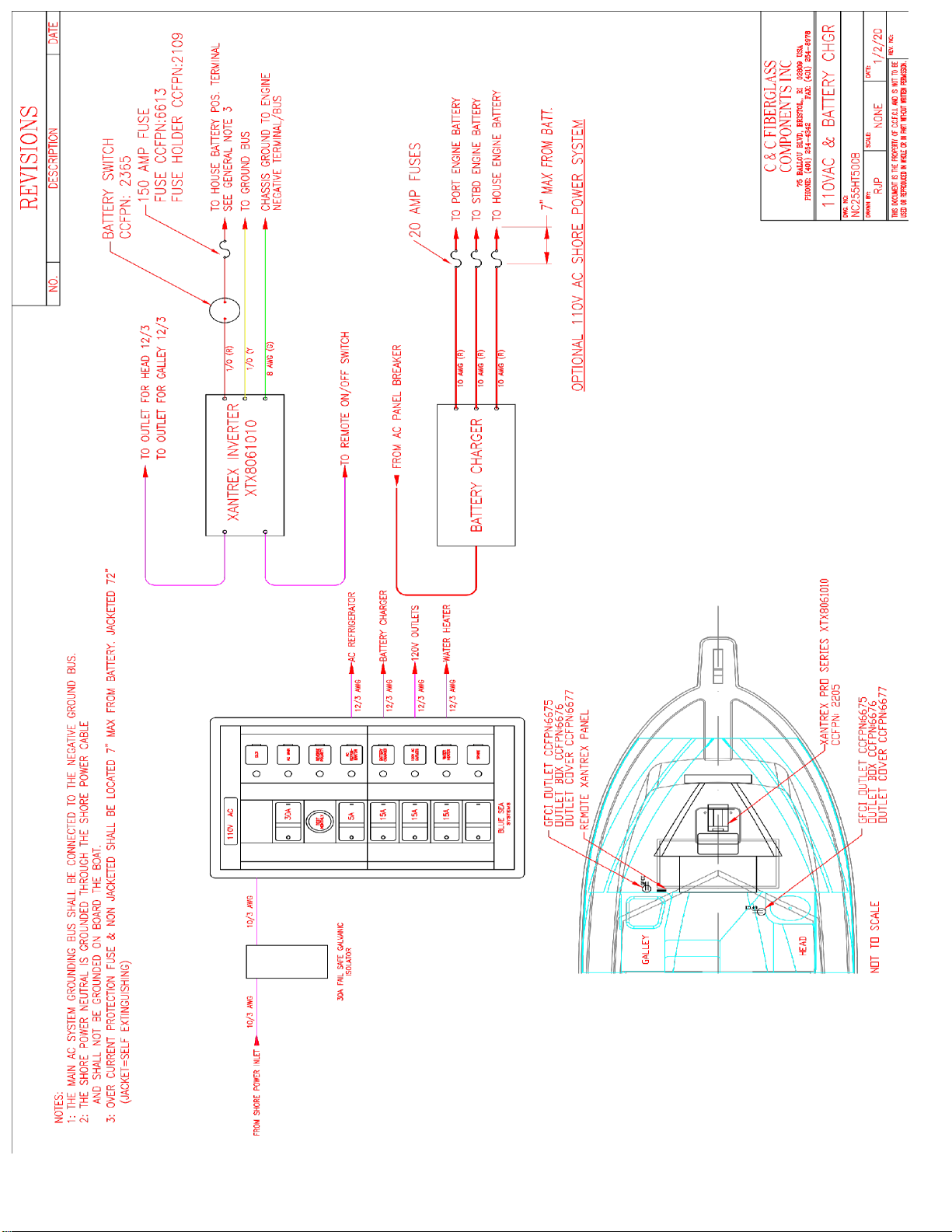
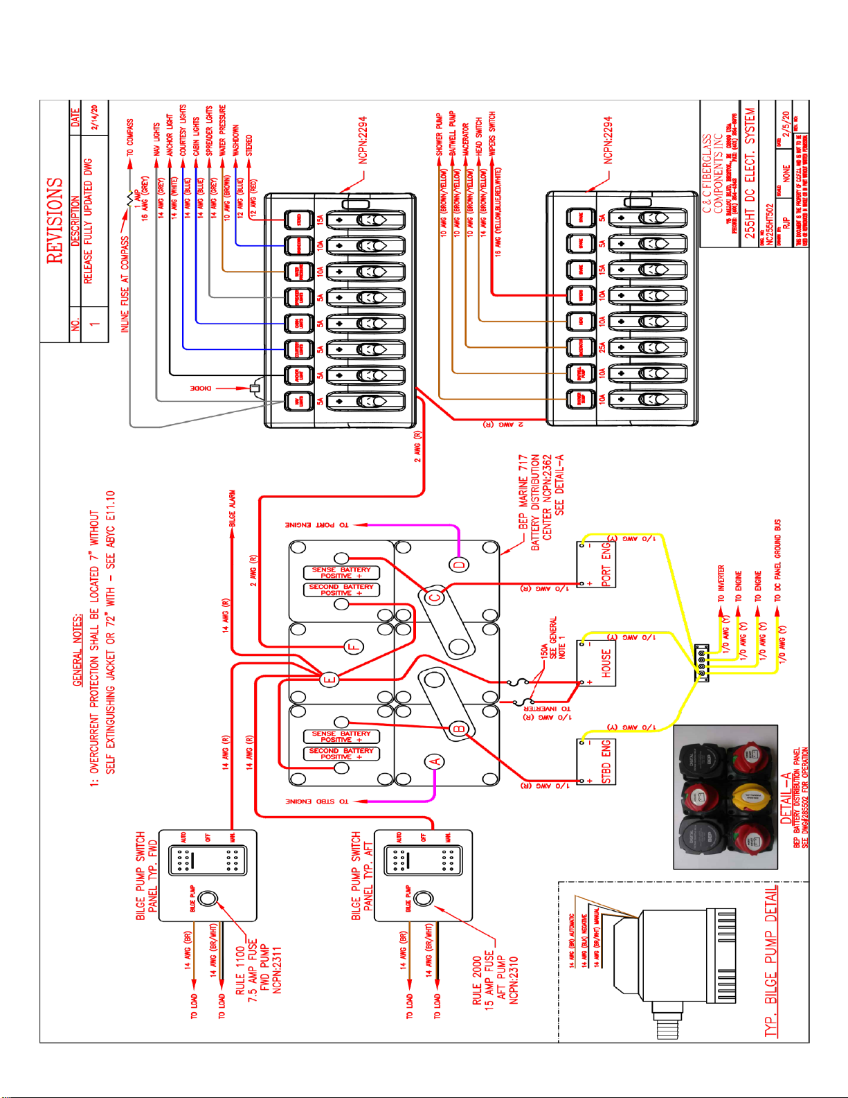
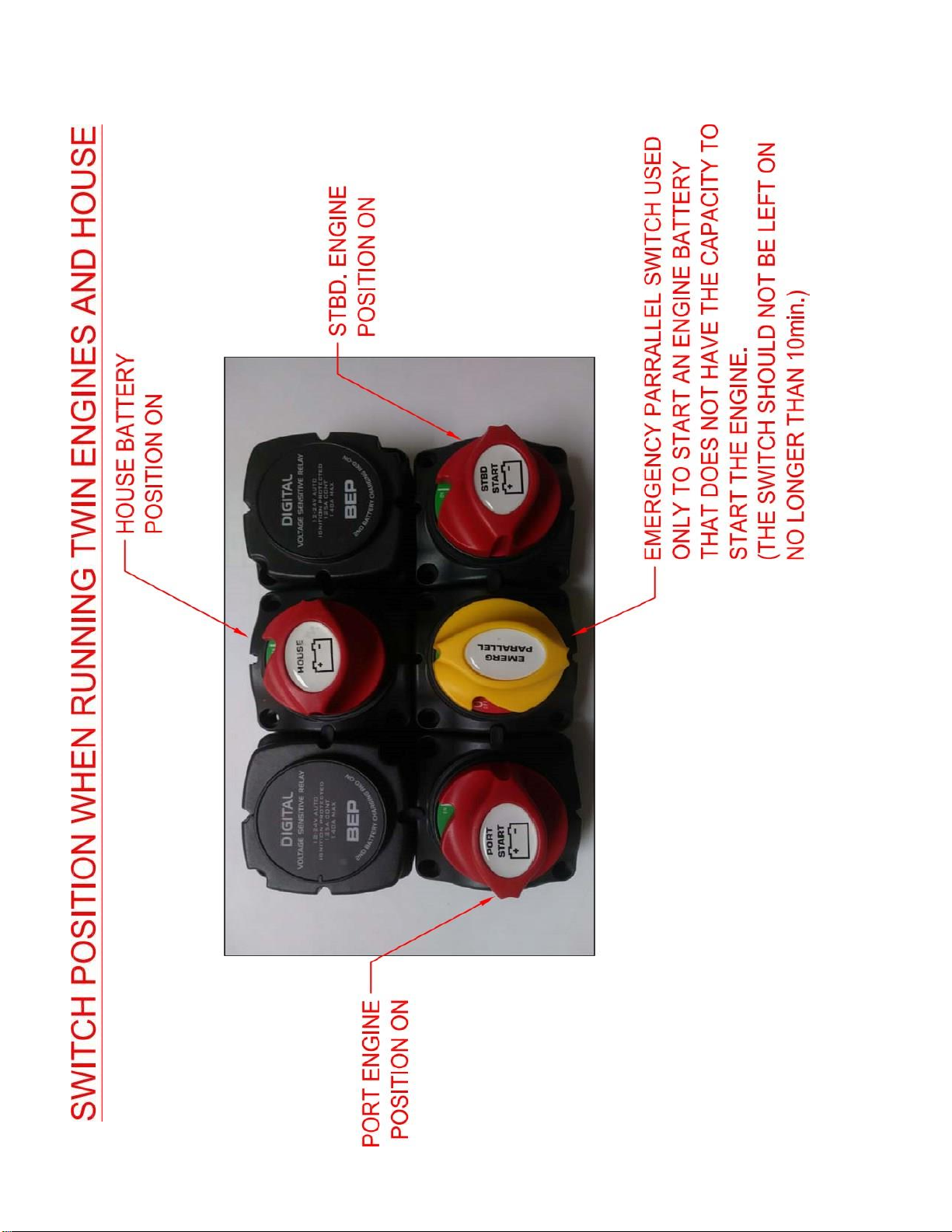
•BATTERY SWITCH
One rotary switch is mounted under by the helm station. These UL listed switches allow
power to go from the house batteries to the main DC panel. The engine batteries can be
supplemented temporarily with the house batteries by means of the paralleling switch at
the helm station. The engine batteries cannot be used in parallel with the house batteries to
power the main DC panel. The battery #1 battery #2 tester on the main DC panel is for
checking the status of the individual house battery banks. Industry convention uses battery
#1 as the "House" battery bank and battery #2 as the Engine battery bank. Battery bank #1
consists of two batteries wired in parallel to increase its capacity.
•BATTERY TEST SWITCH
The voltmeter installed on the electrical panel will give an indication of the charge status
of each of the house batteries. The voltmeter should read between 12.8V and 13.2V for a
fully charged battery. When the engine is charging the battery, the meter should read
between 14.2V and 14.8V.
•MINIMUM VOLTAGE REQUIREMENTS
As the power is used from the battery, the voltage supplied is reduced. To prevent damage
to electrical components, especially motors, do not operate the electrical system if less
than 11.0V is available.
•INDIVIDUAL CIRCUIT BREAKERS
Like the main breaker, the individual circuit breakers are designed to function as switches
as well as provide overcurrent protection. Space is provided for additional breakers if
optional electrical equipment is installed. We recommend that the individual breakers be
activated only as needed and left off otherwise.
•CABIN LIGHTS -- FORWARD
All of the cabin lights in the forward cabin are activated by this circuit breaker.