C&D Technologies LIBERTY 1000 Series User manual

M
Power Solutions
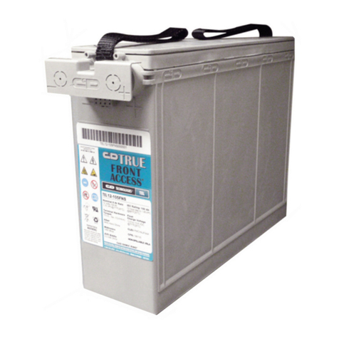
LIBERTY®SERIES 1000 FRONT ACCESS MONOBLOCK
VALVE-REGULATED (SEALED)
LEAD ACID BATTERIES
INSTALLATION AND OPERATING INSTRUCTIONS
RS-1826
FOLLOW MANUFACTURER’S PUBLISHED INSTRUCTIONS WHEN
INSTALLING, CHARGING AND SERVICING BATTERIES.
For additional information and
Technical-Warranty Assistance, contact:
C&D TECHNOLOGIES, INC.
1400 Union Meeting Road, PO Box 3053, Blue Bell, PA 19422-0858
800•543•8630 or 215•619•2700, Fax 215•619•7899
Before handling cells or storing cells for future installation take time to read
this manual. It contains information that could avoid irreparable damage to
the battery and/or void product warranty.

SAFETY PRECAUTIONS
Owners are hereby advised that access to this battery should be limited to personnel who
have been trained in the installation, preparation, charging and maintenance on this specific
battery type and model. WARNING
SHOCK HAZARD - PHYSICAL CONTACT WITH UN-INSULATED BATTERY
CONNECTORS OR TERMINALS SHOULD BE AVOIDED AT ALL TIMES. CARE
SHOULD BE TAKEN TO DISCHARGE STATIC ELECTRICITY FROM ANYTHING
OR ANYONE WHO MAY COME IN CONTACT WITH THE BATTERY BY
MAINTAINING PHYSICAL CONTACT WITH A GROUNDED SURFACE IN THE
VICINITY OF THE BATTERY BUT AWAY FROM THE CELLS AND FLAME
ARRESTERS.
ALL TOOLS SHOULD BE ADEQUATELY INSULATED TO AVOID THE POSSIBILITY
OF SHORTING CONNECTIONS. DO NOT LAY TOOLS ON THE TOP OF THE
BATTERY.
ALTHOUGH C&D TECHNOLOGIES LIBERTY®SERIES 1000 (FAM AND LFA) FRONT
ACCESS MONOBLOCK BATTERIES ARE SEALED AND EMIT NO GAS DURING
NORMAL OPERATION, THEY CONTAIN POTENTIALLY EXPLOSIVE GASES, WHICH
MAY BE RELEASED UNDER ABNORMAL OPERATING CONDITIONS, SUCH AS A
CHARGER MALFUNCTION. THE BATTERY INSTALLATION LOCATION SHOULD BE
A WELL VENTILATED AREA SO AS TO PREVENT HYDROGEN GAS ACCUMULA-
TION IN THE VICINITY OF THE BATTERY FROM EXCEEDING 2% BY VOLUME.
NEVER INSTALL BATTERIES IN A SEALED CABINET OR ENCLOSURE. IF YOU
HAVE ANY QUESTIONS, CONTACT YOUR LOCAL C&D AGENT.
THIS BATTERY CONTAINS SULFURIC ACID, WHICH CAN CAUSE SEVERE
BURNS. IN CASE OF SKIN CONTACT WITH ELECTROLYTE, REMOVE
CONTAMINATED CLOTHING AND FLUSH AFFECTED AREAS THOROUGHLY
WITH WATER. IF EYE CONTACT HAS OCCURRED, FLUSH THE EYE FOR A
MINIMUM OF 15 MINUTES WITH LARGE AMOUNTS OF RUNNING WATER AND
SEEK IMMEDIATE MEDICAL ATTENTION.
WARRANTY NOTICE
This instruction manual is not a warranty. This battery is sold subject to a limited warranty, which is offered in lieu of all other
warranties, express or implied (including the warranties of merchantability or fitness for a particular purpose). A copy of the
applicable limited warranty is available upon written request from C&D TECHNOLOGIES, Inc. 1400 Union Meeting Road PO
Box 3053 Blue Bell, PA 19422-0858 or in Canada C&D TECHNOLOGIES, Inc. 7430 Pacific Circle Mississauga, ON L5T 2A3
Request Warranty Certificate RS-1827.
The data and specifications indicated herein are subject to revision by C&D Technologies, Inc. without notice. While the
information presented herein is believed to be accurate, C&D Technologies, Inc. makes no warranty and hereby dis-
claims all warranties, express or implied, with regard to the accuracy or completeness of the information indicat-
ed herein. Further, because the products featured herein may be used under conditions beyond its control, C&D
TECHNOLOGIES, INC. HEREBY DISCLAIMS ALL WARRANTIES, EITHER EXPRESS OR IMPLIED, INCLUDING THE
WARRANTIES OF MERCHANTABILITY AND FITNESS FOR A PARTICULAR PURPOSE. The user is solely respon-
sible for determining the suitability of C&D Technologies, Inc.’s products for user’s intended purpose and in
user’s specific application.

LIBERTY®SERIES 1000 FRONT ACCESS MONOBLOCK
VALVE-REGULATED (SEALED) LEAD ACID BATTERIES
INSTALLATION AND OPERATING INSTRUCTIONS
TABLE OF CONTENTS PAGE
INTRODUCTION . . . . . . . . . . . . . . . . . . . . . . . . . . . . . . . . . . . . . . . . . 4
PART 1
RECEIVING AND INSTALLATION . . . . . . . . . . . . . . . . . . . . . . . . . . . 6
SECTION 1.1 - RECEIVING . . . . . . . . . . . . . . . . . . . . . . . . . . . . . . . . 6
1.1.1 General Information and Precautions
1.1.2 Safety
1.1.3 Packing, Inspection at time of delivery
1.1.4 Accessories package
SECTION 1.2 - STORAGE . . . . . . . . . . . . . . . . . . . . . . . . . . . . . . . . . 7
1.2.1 Storing charged batteries
SECTION 1.3 - INSTALLATION AND ASSEMBLY . . . . . . . . . . . . . . 8
1.3.1 Installation and connection
1.3.2 Connecting and torquing battery terminal posts
1.3.3 Paralleling batteries
1.3.4 Installation inspection prior to connection
to charging equipment
PART 2
CHARGING AND OPERATION OF BATTERY. . . . . . . . . . . . . . . . . 12
SECTION 2.1 - CHARGING . . . . . . . . . . . . . . . . . . . . . . . . . . . . . . . 12
2.1.1 Boost / initial charge
2.1.2 Initial 1 boost charge
2.1.3 Constant voltage charging
2.1.4 Initial charge records
2.1.5 Warning labels
SECTION 2.2 - BATTERY OPERATION . . . . . . . . . . . . . . . . . . . . . . 14
2.2.1 Float charge
2.2.2 Equalizing charge
2.2.3 Compensating float voltage for ambient temperature
2.2.4 Over-Voltage
SECTION 2.3 - MAINTENANCE OF BATTERY MODULES . . . . . . 17
2.3.1 Inspection
2.3.2 Cleaning modules
2.3.3 Cell voltage variation
2.3.4 Effects of temperature
2.3.5 Record keeping
2.3.6 Connection maintenance
2.3.7 Internal Ohmic measurements
2.3.8 Recommended maintenance
APPENDIX A - MATERIAL SAFETY DATA SHEET . . . . . . . . . . . . 20
APPENDIX B - WARRANTY PROVISIONS. . . . . . . . . . . . . . . . . . . 27
APPENDIX C - VALVE-REGULATED LEAD ACID BATTERY and
CHARGER INSPECTION REPORT FORM. . . . . . . 28
1

WARNING
This battery is designed for industrial use only and is not
intended for application in vehicular starting, lighting, and
ignition and/or operation of portable tools and appliances. The bat-
tery should be used only in accordance with manufacturer’s writ-
ten instructions. Use of this product other than in accordance with
manufacturer's written instructions may produce hazardous and
unsafe operating conditions, leading to damage of equipment
and/or personal injury.
The battery should be charged only in accordance with manu-
facturer’s operating instructions. Do not expose the battery to
open flame or electrical arc. Do not tamper with cell cover or
vents. VRLA batteries contain sulfuric acid, which can cause
severe burns. Mishandling or abuse could cause the battery’s
case to rupture. In case of skin contact with electrolyte, remove
contaminated clothing and flush affected areas thoroughly with
water. If eye contact has occurred, flush one eye thoroughly for
15 minutes with running water and seek immediate medical
attention.
Recommended Tools for Installation and Maintenance
The following list of tools is a general recommendation and is not
intended to be a complete list. Each installation may require special
tools which can not be specified without specific knowledge of the
installation.
Safety
1. Rubber or Neoprene - Acid resistant gloves.
2. Protective apron
3. Face Shield or goggles (ANSI approved).
4. Rubber soled safety shoes/boots.
5. Insulated tools.
6. Portable eye wash for rinsing of eyes in case of contact with
electrolyte.
Installation
1. Lifting sling or platform (dependent on battery size and
weight).
2. Insulated tools.
3. Torque wrench.
4. Digital voltmeter (three digit accuracy).
5. Resistance, conductance or impedance meter. (Select one
method)
6. Non-metallic brush or pad for cleaning connections.
7. No-Ox-Id grease and brush.
2

3
Maintenance
1. Digital voltmeter w/ temperature probe.
2. Torque wrench.
3. Insulated wrenches.
4. Resistance, conductance or impedance meter.
Warning: Do not, under any circumstances, use any petroleum
based cleaning or lubricating solutions on the battery jar or cover.
Failure to follow this warning may result in cracked or broken jars
and will void the warranty.
NOTE: Keep these Installation and Operating Instructions and
Layout drawings (if any) near the battery installation at all times.

INTRODUCTION
The batteries referenced in this document are sealed lead acid batteries
referred to as FAM and FA batteries. They are constructed with an
absorbent glass-mat and are valve-regulated with pasted lead-calcium
plates. They are designed to provide long, reliable service life with
minimal maintenance. When operated at the recommended float voltage
and temperature, the batteries emit virtually no gas or acid mist and do
not require special ventilation to be operated safely other than what is
generally required by local building codes. However, VRLA batteries
should never be installed in a sealed enclosure or cabinet.
4

5
RECOMMENDED TECHNICAL REFERENCES AND EXPERTISE
This battery should be installed by a competent professional
who has been trained in the installation of this specific type of
battery. While not intended to be a complete list, the following
recommended practices and codes contain relevant information,
and should be consulted for safe handling, installation, testing
and maintaining standby batteries. Applicable state and local
codes must be followed.
IEEE Std. 485-Latest Rev., IEEE Recommended Practice for Sizing
Large Lead Acid Storage Batteries for Generating Stations and
Substations (ANSI)
IEEE 1189-Latest Rev., IEEE Guide for Selection of Valve-Regulated
Lead Acid (VRLA) Batteries for Stationary Applications
IEEE 1188-Latest Rev., IEEE Recommended Practice for
Maintenance, Testing, and Replacement of Valve-Regulated Lead
Acid Storage Batteries for Stationary Applications
IEEE 1187-Latest Rev., IEEE Recommended Practice for Installation
Design and Installation of Valve-Regulated Lead Acid Storage
Batteries for Stationary Applications
IEEE - PAR-1375 “Guide for Protection, Standby Batteries”
NESC, National Electric Safety Code, ANSI C2-1993 (or latest revision)
Copies may be obtained by writing:
The Institute of Electrical and Electronic Engineers, Inc.
345 East 47 Th. Street, New York, NY 10017, USA, www.ieee.org
ANSI-T1.330-Latest Rev., Valve-Regulated Lead Acid Batteries used
in the Telecommunications Environment
NEC National Electrical Code NFPA -70 (latest version) available from:
National Fire Protection Association Batterymarch Park, Quincy, MA
02269
Federal Codes:
29CFR1926.441 “Safety Requirements for Special Equipment”
29CFR1910.151(c) “Medical Services and First Aid”
29CFR1910.268(g) “Telecommunications”
29CFR1910.305(j) “Wiring Methods, Components and Equipment”
STD 1-8.2(e) “OSHA Standing Directive”
UBC, Uniform Building Code

6
PART 1
RECEIVING AND INSTALLATION
SECTION 1 - RECEIVING
1.1.1 General Information and Precautions
This battery is designed for industrial use only and is not intended for
application in vehicular starting, lighting, and ignition, and/or
operation of portable tools and appliances. Use only in
accordance with manufacturer's written instructions. Use of this
product other than in accordance with C&D TECHNOLOGIES, INC.’s
written instructions may produce hazardous and unsafe operating
conditions, leading to damage of equipment and/or personal injury.
1.1.2 Safety
Charge only in accordance with C&D TECHNOLOGIES, INC.’s
operating instructions.
Do not expose to open flame or electrical arc.
Do not tamper with cell covers or vents. There is no need to remove
vents for water addition.
Observe all precautions shown on the inside cover of this manual and
page 2.
1.1.3 Packing, Inspection at time of delivery
Resonable precautions have been taken to pack the battery for shipment
to ensure its safe arrival. As soon as you receive the battery, inspect the
packing material for evidence of damage in transit. If the packing
material is physically damaged or stains are present, make a notation on
the delivery receipt before you accept the shipment / delivery.
Note: Freight Carriers generally require that concealed damage be
inspected by the carriers representative within 15 days from date of
delivery to determine responsibility. The resolution of such claims
may extend up to 9 months.
1.1.4 Accessories package
Check the contents of the accessories package against the enclosed
packing list to determine all connecting hardware and cables have been
received. Place accessories in a safe location where they can be easily
retrieved. If parts are missing from the package, contact the customer
service department at C&D TECHNOLOGIES, attention Customer
Service, 1400 Union Meeting Road, Blue Bell, PA 19422, 800-543-
8630, within 30 days of receipt at original destination.

7
SECTION 2 - STORAGE
1.2.1 Storing Charged Batteries
Store batteries indoors in a cool, dry location between 20°F (-7°C)
and 90°F (32°C) and place the batteries in service within 6 months
after the manufactured date found on each battery module.
NOTE: Batteries which are not placed in service for several months will
self-discharge. Boost charges may be applied to individual units or
preferably, to the entire battery module. Do not let electrolyte freeze.
TABLE 1 - FREEZING TEMPERATURE VS SPECIFIC GRAVITY
Storage limitations
The FAM and FA batteries are warranted against defects in materials or
manufacturing or both for a period of two years from the date of ship-
ment. To keep the warranty in effect, you must place the units on charge
by the date stamped on the shipping carton when stored at 77°F (25°C).
If storage beyond this time is required or storage temperature is in excess
of 77°F (25°C), monitor battery voltage at monthly intervals, if possible. A
convenient measurement technique is to read the open circuit voltage. If
the open circuit voltage drops by 0.04 volts per cell from the nominal
value, the cell(s) must be given a boost charge at the “Initial/Equalize”
voltage. If the batteries are stored for longer than six months without a
boost charge, apply a boost charge to the batteries for 12-24 hours at
2.33 vpc. If the battery has less than 13.3 volts on float contact C&D
TECHNOLOGIES Technical Services Department for special instructions.
Always complete the record of initial charge and float charge
readings as described in the initial charge section of this manual and
retain the readings in your files for future warranty reference. Clearly
identify your location, the application, C&D model number, the date,
and name of the person who took the readings.
The service life of your battery will depend on its ambient
temperature, frequency and depth of discharge, discharge rate,
charge voltage, and regulation of the battery charger.
1.000 0.0 +32
1.050 -3.3 +26
1.100 -7.7 +18
1.150 -15 +5
1.200 -27 -17
1.250 -52 -61
1.300 -70 -95
1.350 -49 -56
1.400 -36 -33
Celsius
Specific Gravity
at 77°F (25°C) Freezing Temperature
Fahrenheit

8
SECTION 3 - INSTALLATION AND ASSEMBLY
1.3.1 Installation
Liberty®Series 1000 FAM and FA batteries are best installed horizontal-
ly. Physical dimensions for layout may be found in Table 1. Install battery
in a cool, dry location away from heat sources. The recommended oper-
ating temperature (ambient) is 65-77°F (18-25°C). The allowable tem-
perature range with performance degradation at the extreme tempera-
tures is 32-90°F (0-32°C). Float voltage compensation should be made
for temperatures other than 77°F (25°C).
NOTE: Units connected within a battery string are connected in
series positive post to negative post to positive post, etc.
If possible the application should allow at least 3/8 of an inch
between batteries for proper inter-connection spacing and air circula-
tion. When handling units never lift them by the terminals as this can
damage the post seals and cause acid leakage.
Avoid sources of hot or cold air directed on a section of the battery
that could cause temperature variations within the battery assembly.
Such variations will compromise optimum battery performance such
as float voltages of individual cells.

Model FAM 12-100 FA 12-125* FAM 12-150
Nominal 12 volts 12 volts 12 volts
voltage
Number 6 / Unit 6 / Unit 6 / Unit
of cells
Rated 8-hr
capacity
(ampere-
hours to
1.75 Vpc)
Internal 0.00042 0.000589 0.00043
resistance Ohms Ohms Ohms
Short
circuit
current
Unit 9.05 in. 10.12 in. 12.63 in.
height (230 mm) (257 mm) (323 mm)
Unit
length
(includes
handles)
Unit width 4.94 in. 6.93 in. 4.94 in.
(125 mm) (176 mm) (125 mm)
Weight 80 lbs. (41 kg) 120 lbs. (55 kg) 131 lbs. (60 kg)
Plate
thickness
positive
(3.55 mm)
negative 0.085 in. 0.088 in. 0.085 in.
(2.16 mm) (2.23 mm) (2.16 mm)
Threaded copper- Threaded copper- Threaded copper-
brass insert. brass insert. brass insert.
Fasten with Fasten with Fasten with
1/4-20 stainless 1/4-20 stainless 1/4-20 stainless
steel hex steel hex steel hex
bolt/washer. bolt/washer. bolt/washer.
9
TABLE 1 BATTERY SPECIFICATIONS
*
FA 12-125 consists of (2) FA 6-125 units in an epoxy-painted steel jacket.
100 Ah to
10.5 volts
125 Ah to
10.5 volts
150 Ah to
10.5 volts
4000 A 2600 A 4610 A
21.95 in.
(558 mm)
16.60 in.
(415 mm) 21.95 in.
(558 mm)
0.140 in.
(3.81 mm)
0.150 in.
(3.55 mm) 0.140 in.
Terminal

FV/Time Models 1 hr. 3 hr. 5 hr. 8 hr. 10 hr. 20 hr.
FAM 12-100 66.3 28.1 18.5 12.4 10.2 5.5
1.75 FA 12-125 86.3 37.1 24 15.8 12.9 6.8
FAM 12-150 99.9 43 28.1 18.8 15.4 8.2
FAM 12-100 64.7 27.6 18.2 12.3 10.1 5.4
1.80 FA 12-125 83.2 35.8 23.2 15.4 12.6 6.6
FAM 12-150 96.2 42.4 27.8 18.6 15.3 8.1
FAM 12-100 1 hr 3 hr 5 hr 8 hr 10 hr 20 hr
1.84 FA 12-125 78.7 34 22.2 14.7 12.1 6.4
FAM 12-150 92.4 41.7 27.5 18.4 15.1 8
FAM 12-100 57.6 25.3 16.7 11.3 9.3 5
1.88 FA 12-125 72.8 31.6 20.7 13.8 11.3 6
FAM 12-150 92 41.2 27.3 18.3 15 8
FAM 12-100 55.1 24.3 16.1 10.9 9 4.8
1.90 FA 12-125 69.1 30.1 19.7 13.2 10.8 5.8
FAM 12-150 85.3 40.4 27 18.2 14.9 7.9
Ratings in Amperes at 77°F (25°C)
10
C&D Front Access products meet or exceed IEEE-485 at time of shipment.
Additional rates are available at www.cdstandbypower.net

11
1.3.2 Connecting and torquing battery terminal posts
FAM and FA batteries are available in three 12 volt modules sizes
with the following ampere - hour ratings at the 8 hour rate of dis-
charge: 100 Ah, 125 Ah and 150 Ah. Each of the 12 volt modules is
terminated with two terminals one each for positive and negative
connections. The modules are connected positive to negative from
one module to another module in a series arrangement. This is
accomplished by fastening the connector or cable lugs from the
positive terminal of a module to the negative terminal of the next
module. The lug or connector is secured with the appropriate terminal
hardware described in Table 1 and tightened to the torque value
specified in Table 1.
1.3.3 Paralleling batteries
If the capacity requirement of the system requires more ampere
hours than that available in one battery, up to (8) eight batteries of the
same ampere hour size may be connected in parallel. More parallel
strings may be possible dependent on application parameters and
design. Each battery must be of the same voltage and size.
1.3.4 Installation inspection prior to connection to charging
equipment
• Check again that all modules are connected positive terminal to
negative terminal. Measure the battery, voltage with a digital
voltmeter. The voltage should be approximately 12.9 (see table)
volts (open circuit) times the number of modules connected in
series. Example: 12.9 volts x 4 (FAM12-150) = 51.6 volts, repre-
senting a nominal 48 volt system.
• Recheck torque value to make certain that there are no loose
connections that could cause a poor connection possibly creating
an arc or spark or a hot connection that on discharge could melt
the lead components.
• Follow the charger manufacturers instructions and make the
connections to the battery with the charger de-energized.
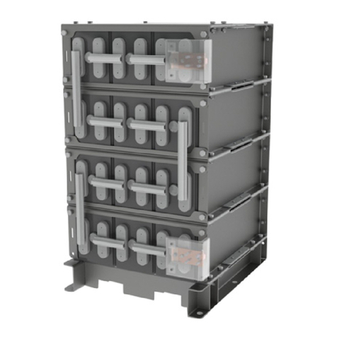
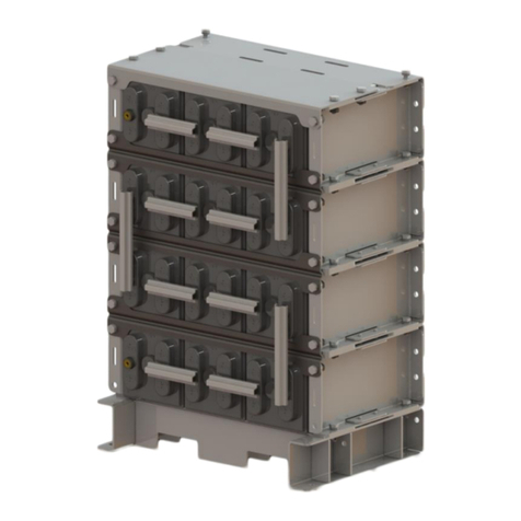
(Other Rack Layouts
Are Available)

PART 2
CHARGING and OPERATION OF BATTERY
SECTION 1 - CHARGING
CAUTION
Always recharge a battery immediately
after a discharge to avoid degradation of the plates.
2.1.1 General Information and Precautions
To safely charge the Liberty Series 1000 Front Access batteries and
avoid damaging the battery and/or connected equipment, observe
the following:
• Use only direct current for charging. AC ripple current from charger
shall not exceed 5 percent of the 8-hour (Ampere-hour) rating of
the battery.
• Be sure charger is turner off before making electrical connections
between the battery abd system.
•Connect battery positive terminal to charger positive terminal and
battery negative terminal to charger negative terminal. Grounding
battery may be either to positive or negative terminal of the battery.
This will depend upon the system design.
• Be certain that all connections are tight and secured before turning
on the charger.
2.1.2 Initial 1 boost charge
All cells/units are shipped fully charged but will lose some charge in
transit or storage before installation. At the first opportunity, provide an
initial charge. This should be done at least by the date stamped on the
shipping container if batteries are stored in a clean, dry and cool
(between 32°F-77°F [0°C-25°C]) location.
12
CAUTION
If the proper polarities are not observed when charging the
battery, the battery or groups of reverse-connected cells will
be irreparably damaged.
CAUTION
Valve-regulated batteries must receive a boost charge if
installation will not occur by the date on the carton or if open
circuit voltage drops to 2.11 Volts per cell. Multiply the open
circuit voltage by the number of cells in a unit to obtain unit
voltage. Use initial/equalize charge voltages as shown in Table
2 or Table 3 for boosting cells at the Initial/Equalize Voltage.

Higher than normal storage temperature (77°F [25°C] nominal) will acceler-
ate internal self-discharge of a battery by a factor of two for each 15°F (9°C)
over nominal 77°F (25°C) storage temperature. This, in turn, will reduce the
allowable time before initial and subsequent charging.
Therefore it is very important that boost charges be given at the
appropriate time to avoid major remedial action or damage to
product.
All batteries, including Liberty Series 1000 Front Access, are capable of
generating potentially explosive gases when charged at higher than normal
voltages typical of initial or equalizing charge. The Liberty Series 1000 Front
Access cells are equipped with a “flame arrestor and pressure relief valve”
assembly that seals the cells during normal charge and operation but allows
it to safely vent in case of overcharge. Removing the cover and/or valve
assembly can cause the release of potentially explosive gases and such
action will void the warranty.
2.1.3 Constant voltage charging
The recommended method of providing an initial/equalize charge is to first
determine the maximum allowable voltage that may be applied to the con-
nected equipment. Divide this by the number of cells in the battery to obtain
maximum average voltage per cell allowed by the equipment. Adjust this
number down to a recommended initial value found in Table 3 and continue
charging at this voltage for the time specified. Next put the battery at the
recommended float voltage for a minimum of 72 hours before any load is
placed on the system. The battery is now considered fully charged and is
ready for either initial acceptance testing or regular service.
Use only direct current for charging. AC ripple current from charger shall
not exceed 5 percent of the 8-hour (Ampere-hour) rating of the battery.
Charges should be current limited to 25 ampere per 100AH of the 8-hour
rating of the battery.
13
CAUTION
Never expose a cell or battery to sparks or an open flame.
When working on a battery, discharge static electricity on the
body, tools, etc., by touching a grounded surface in the
vicinity of the battery rack.
CAUTION
Excess charge current can increase the battery temperature.
The increase in battery temperature will have an effect on
battery life.

14
2.1.4 Initial charge records
At the completion of the initial charge and after the cells have been on
float charge for approximately one week, record voltages of the
individual cells or units, the total battery voltage and ambient
temperature. Retain this information in your files for future reference.
This information establishes one baseline for future reference. Refer to
RS-1511 found in the appendix. Make a photocopy of the form and
use it whenever necessary to record readings taken on the battery.
IMPORTANT: Initial charge records and on-going maintenance
records are essential for review by C&D TECHNOLOGIES sales/
service agents in the event of a problem. Since records can materially
affect your warranty, be sure to maintain clear, signed, and dated
copies.
2.1.5 Warning labels
C&D TECHNOLOGIES, INC. provided a warning label to assist in
maintaining standby batteries and to advise you of certain hazards.
This label may be found on the battery cover visible to anyone in
the immediate vicinity of the battery. Make certain that all individuals
who could be operating near the battery read the warning that is
intended to inform the individuals of basic safety practices.
SECTION 2 - BATTERY OPERATION
2.2.1 Float charge
The normal charging voltage to maintain the battery is called “Float
Charge” and is provided at a potential slightly higher than the full
charged open circuit voltage. The over potential is required to main-
tain properly polarized plates within the VRLA battery. Float voltages
may vary from 2.24 - 2.26 volts per cell at 77°F (25°C) depending
upon the frequency and depth of discharges.
Assuming full float service a (6) six cell 12 volt module should
be floated at 13.67 volts +/- .06 volts at 77°F (25°C).
2.2.2 Equalizing charge
Under normal operating conditions, it should not be necessary to
equalize batteries when charged at the recommended voltage in Table
2. An equalizing charge delivered at a voltage higher than the nominal
float voltage is used to restore uniform cell voltage to a battery.
Note 1: Some hydrogen gas may be liberated at equalize charging
voltage.
FLUSH EYES
IMMEDIATELY
WITH
WATER.
GET
MEDICAL
HELP FAST
U.S. PAT. 4683647, 4752545, 5593796
OTHER PATENT PENDING
Leola, PA (800) 543-8631
DANGER
HIGH VOLTAGE…
RISK OF SHOCK. DO NOT
TOUCH UNINSULATED
TERMINALS OR
CONNECTORS
SHIELD
EYES
EXPLOSIVE
GASES
CAN CAUSE
BLINDNESS OR INJURY
NO
• SPARKS
• FLAMES
• SMOKING
SULFURIC
ACID
CAN
CAUSE BLINDNESS
OR SEVERE BURNS
“DO NOT REMOVE VENT VALVES.” VENTILATE WELL WHEN IN AN ENCLOSED
SPACE AND WHEN CHARGING.
SEE INSTALLATION, MAINTENANCE AND OPERATION
INSTRUCTIONS FOR IMPORTANT SAFETY PRECAUTIONS. REPAIR SHOULD BE PERFORMED ONLY BY
A QUALIFIED SERVICE TECHNICIAN.
TORQUE SPECIFICATIONS
MODULE TO MODULE 25 - 30 ft-lb
TERMINAL PLATES 160 in-lb
TERMINAL TO NON- 5 ft-lb (INITIAL)
CONDUCTING MATERIAL 15 ft-lb (RE-TORQUE)
CONNECTORS 160 in-lb
®

15
An equalizing charge can be provided when individual cell voltages go
below the minimum value shown in Table 3 or 0.05 Volts below the float
voltage specified in Table 3. Remember to divide the number of cells into unit
voltage to arrive at cell voltage.Presence of a minimum voltage does not
imply a battery is malfunctioning or that it will not provide the necessary
power when called upon.
Note 2: Chargers must be current limited to 25 Amperes per 100-Ampere-
hour battery rating. Higher charging currents could potentially
destroy the battery by overheating that subsequently causes more
current to flow creating a vicious cycle sometimes referred to as
“thermal runaway.”
Note 3: Minimium voltage is the point at which plans should be made to
provide an equalizing charge. Note that the normal equalize voltage
level (initial charge level) will not be effective in VRLA product as the
voltage is not high enough to enable the negative plates to charge.
An equalizing charge of 2.45 volts per cell can be applied to the
string or problem cell/unit for a period not exceeding eight hours.
Consult the C&D TECHNOLOGIES Technical Service Department
for answers to specific questions.
2.2.3 Compensating float voltage for ambient temperature
VRLA batteries should ideally be operated at 77°F (25°C) to obtain optimum
performance and life. If it is necessary to operate outside this temperature it
is advisable to increase the float potential by 3 mV/F° (3.6 mV/C°) for lower
temperatures and lower the float by 3 mV/F° (3.6 mV/C°) for higher tempera-
tures. See Table 2 below.
TABLE 2
RECOMMENDED FLOAT VOLTAGE SETTINGS
AMBIENT TEMPERATURE RANGE
NOTE: The life of a battery will be reduced 50% for each 15°F increase in
operating temperature above 77°F. See Table 3 on page 15.
67°F-87°F* 80°F-100°F 90°F-110°F 100°F-120°F
(19°C-31°C) (27°C-38°C) (32°C-43°C) (38°C-49°C)
VOLTS 2.25 2.24 2.22 2.20
PER +/- +/- +/- +/-
CELL 0.01 0.01 0.01 0.01
Farenheit
Celsius

TABLE 3
CHARGE VOLTAGES FOR
LIBERTY SERIES 1000 FRONT ACCESS CELLS
CHARGE VOLTAGES AT 77°F (25°C)
Note 1:
1- Applies to average cell voltage. Battery voltage should be set at average cell voltage multiplied by the number
of cells in unit or string. Individual cell voltages may vary by +/- 0.05 Volts from the average.
2 - Charging time will vary due to open circuit stand, temperature and charger voltage available.
3- If cell temperature is below 60°F (16°C), double the charge time for initial or equalize charge.
Note 2:
All lead-acid batteries lose a certain amount of charge when removed from a constant voltage source charger,
set at a potential that is higher than the open circuit potential of the battery. As the charge is lost, the electro-
chemical process produces lead sulfate in the positive and negative plates of every cell in the battery. If left
uncharged for a significant period of time, the lead sulfate will begin to form large crystals of lead sulfate.
Because of their size, these crystals may be somewhat difficult to reduce (break down) through normal charging
procedures and may inhibit the complete electro chemical process necessary to sustain a healthy lead-acid bat-
tery. Frequently, higher-than-normal charging potentials or even more sophisticated remedial approaches may
be necessary to recover the affected battery. In cases of sever sulfation, replacement may be the only solution.
2.2.4 Over-Voltage
When a charger is improperly set or a panel meter is improperly calibrated battery
over-voltage or under-voltage may result. Higher than normal battery voltage can
damage a battery, significantly shortening its service life. This is especially impor-
tant in valve-regulated product where over-voltage increases gas generation that
could cause pressure build-up within the cell. The excess pressure will cause the
cells to vent the gases generated, causing premature dry out of the battery elec-
trolyte.Even a small increase in over-voltage, beyond what is recommended in
Table 2, increases the corrosion rate of the positive grid element and will contribute
to reduced battery life. To avoid over-voltage, periodically check battery voltage
with a calibrated digital voltmeter. If an over-voltage is recorded, check and read-
just the rectifier and/or panel meter calibration as necessary. Place the battery at
the recommended float charging voltage as soon as possible. Restoring the proper
float voltage will preclude further damage caused by charging at an over-voltage
but it cannot reverse damage that has already been sustained by the battery.
CAUTION
Liberty Series 1000 batteries produce virtually no gas emissions during
normal operation. However, potentially explosive gases may be released
under abnormal operating conditions or initial/equalize charge. Provide
adequate ventilation so hydrogen gas accumulation in the battery area
does not exceed one percent. Do not smoke, use open flame or create
sparks near battery.
Cell Type Open Minimum Float Voltage Initial Charge Typical Charging
Circuit Cell (Vpc) Voltage (Vpc) Time for Initial
(Vpc) Voltage (Vpc) Charge
All Liberty 2.15 2.20 2.26 +/– 0.01 2.33 +/– 0.02 12–16 Hours
Series 1000®
FA & FAM
16

SECTION 3 - MAINTENANCE OF BATTERY MODULES
2.3.1 Inspection
Liberty 1000 Series Front access modules are sealed VRLA valve-regulat-
ed lead acid batteries and never require the addition of water.
WARNING: Never remove the vents as this will degrade the
battery seal and will void the warranty.
2.3.2 Cleaning Modules
Use only a damp cloth to clean modules. Do not use any cleaning
agents, because they could damage the battery cases.
WARNING: Do not clean modules with a dry cloth since this
could develop a static charge on the plastic containers resulting
in a potential spark.
2.3.3 Cell voltage variation
It is expected that module voltages will vary throughout the normal life
of the battery. An acceptable variation of +/- 0.05 volts from the nom-
inal cell float voltage is satisfactory. As an example a 12 volt module
floating at 2.26 volts per cell or 13.56 volts for the module may vary
from 13.26 to 13.86 volts measured at 77°F (25°C) and be accept-
able.
2.3.4 Effects of temperature
A lead-acid battery is an electro chemical device. Heat accelerates
chemical activity; cold slows it down. Normal battery operating tem-
perature is 77°F (25°C). Higher than normal temperatures have the
following effects on a lead-acid battery:
• Increases capacity
•
Shortens life
17
LIBERTY SERIES 1000 FAM AND FA BATTERY
WARRANTY INFORMATION
Warranty period Maximum annual
average temperature
2Years full
8Years pro-rata 77°F (25°C)
1 Year full
4 Years pro-rata 92°F (33.3°C)
1⁄2Year full
2Years pro-rata 107°F (43.3°C)
3 Months full
1 Year pro-rata 122°F (48.8°C)
TABLE 4

• Increases internal discharge or local action losses
• Lowers cell voltage for a given charge current
• Raises charging current for a given charge voltage
• Increases the rate of dry-out of electrolyte
Lower than normal temperatures have the opposite effect and
reduce capacity. In general, at proper float voltage, a battery in a
cool location will last longer than one in a warm location.
Note: No temperature correction is required when operating at
77°F +/- 10°F, (25°C +/- 5.5°C). The following correction
factors apply for range not exceeding +/- 30°F from
nominal. For further assistance with temperature correction
factors, contact C&D TECHNOLOGIES.
If the operating temperature is other than 77°F (25°C), it is recom-
mended that the float voltage be changed as follows:
For temperatures other than 77°F (25°C), correct float voltage by
2 mV per degree F (3.6 mV per degree C):
• Add 2 mV (0.002 Volts) per degree F (3.6 mV per degree C)
below 77°F (25°C)
• Subtract 2 mV (0.002 Volts) per degree F (3.6 mV per degree C)
above 77°F (25°C)
Note: Temperature compensation will materially improve battery
service life when provided.
2.3.5 Record keeping
As a minimum annual measurements of module voltage should be
taken and recorded. On occasion, if a long discharge has been
experienced, completely recharge the battery and take a set of
voltage readings recording them for future reference if the readings
are satisfactory.Provide remedial action or an equalize charge if
necessary. Do not discharge a battery below the design final
voltage. Remedial action may be required if the battery was
discharged below its final design voltage. Very deep discharges can,
without an immediate recharge, completely deplete the electrolyte and
cause hydration. Failure to maintain records may void the warranty.
2.3.6 Connection maintenance
Check the torque of bolted connections annually. Refer to table 1 for
initial torque values.The same value may be used for re-torque.
Examine the connections for cleanliness and indicate any required
action on your records.
18
Other manuals for LIBERTY 1000 Series
1
Table of contents
Other C&D Technologies Camera Accessories manuals
Popular Camera Accessories manuals by other brands

EINHELL
EINHELL Power-X-Change 18 V Original operating instructions

Zacuto
Zacuto Gratical EVF user manual

Rollei
Rollei Lion Rock Traveler S Black Edition user manual

ElectrIQ
ElectrIQ PowerPod 2 installation manual

Phottix
Phottix PPL-200 quick start guide

ionGen
ionGen GTX12V630A-E2112-CS200 Installer's guide