C&D Technologies TEL Series User manual

RS02046
Installation and Operating Procedures
For C&D Technologies TRUE Front Access TEL Series Batteries
FOLLOW MANUFACTURER’S PUBLISHED INSTRUCTIONS WHEN
INSTALLING, CHARGING AND SERVICING BATTERIES.
For additional information: www.cdtechno.com
Technical-Warranty Assistance, contact:
C&D Technologies, Inc.
1400 Union Meeting Road / PO Box 3053 / Blue Bell, PA 19422-0858
800-543-8630 or 215-619-2700
Fax 215-619-7899
Before handling cells or storing cell for future installation take time to read this manual. It contains
information that could avoid irreparable damage to the battery and/or void product warranty.
RS02046/0514/CD www.cdtechno.com

General:
The purpose of this manual is to inform installers how to receive, install and maintain C&D Technologies front
access batteries.
Battery Description:
The Valve Regulated Lead Acid (VRLA) battery is a minimal maintenance system utilizing an oxygen
recombination cycle to minimize gassing and eliminate electrolyte maintenance. The dilute sulfuric acid
electrolyte is immobilized by absorbent glass mat (AGM) separators.
Each of the 2 VDC cells (6 cells per
unit)
in each unit has a unique self-resealing one
way valve to relieve any excess pressure
generated
during overcharging conditions. Four six cell units in series make up a 24 cell 48VDC battery, two six cell
units in series for a 12 cell 24VDC applications.
See Section IV. Installation Instructions-for further descriptions.
Model Bus Bar
Connector
Hardware
Package (two
SS Bolts &
two SS
washers)
Protective
Terminal
Cover
Lifting
Handle Gas Collection
Plug Kit Gas Collection
Tubing Kit
TEL12-
105FNSG/FNS (1) 15028536
8mm x 16
(1) 15028540 (2) 15028591 15028595* 15028596*
(1) 15028538
TEL12-
115FN/FNG (1) 15028537
6mm x 16
(1) 15028540 (2) 15028591 15028595* 15028596*
(1) 15028539
TEL12-145FW (1) 30046795
6mm x 16
(1) 15028594 (2) 15029231 N/A N/A
(1) 15028539
TEL12-
155F/FG (1) 15028593
8mm x 16 (1)
(1) 15028594 (2) 15028591 15028595* 15028596*
15028538
TEL12-160F (1) 30046800
1/4-20 x 3/4
(1) 15029218 (2) 15029217 N/A N/A
(1) 15028506
TEL12-160FW (1) 30046795
¼-20 x 3/4
(1) 15029218 (2) 15029217 N/A N/A
(1) 15028506
TEL12-
170F/FG (1) 15028593
8mm x 16
(1) 15028594 (2) 15028591 15028595* 15028596*
(1) 15028538
TEL12-180F (1)30046800
¼-20 x 3/4
(1) 15029218 (2) 15029217 N/A N/A
(1) 15028506
TEL12-
190F/FG (1) 15028593
8mm x 16 (1)
(1) 15028594 (2) 15028591 15028595* 15028596*
15028539
TEL12-
210F/FG (1) 15028593
8mm x 16
(1) 15028594 (2) 15028591 15028595* 15028596*
(1) 15028538
TEL12-210Fa
(1)30046800
¼-20 x ¾
(1) 15028506 (1) 15029218 (2) 15029217 N/A N/A
*Models with “G” suffix only
Hardware, terminal protector, and bus bar indicated above is individually packaged within the insert on the top of the
battery, inside the shipping carton of each 12 volt battery unit. Batteries ordered without cartons (bulk) do not include
connector or hardware.
Safety Glasses for each installer
Insulated gloves (1 pair for each installer)
Digital Voltmeter
Terminal Prep Supplies (water, baking soda, cloth rag, brass bristle brush or scotch brite type pad, NO-OX-ID terminal
grease)
Insulated Inch Pound Torque Wrench (up to 160 in lb)
Insulated 7/16” socket wrench for TEL12-105FS, TEL12-160F, TEL12-160FW, TEL12-180F &
TEL12-210Fa models
Insulated 10mm socket wrench for TEL12-115FN/FNG & TEL12-145FW models
Insulated 13mm socket wrench for TEL12-105FNSG/FNS,TEL12-155F/FG, TEL12-170F/FG,
TEL12-190F/FG, TEL12-210F/FG models
Utility knife or diagonal cutter (for trimming protective covers and gas collection tubing if used)
Battery Numbers and String Letters/Numbers
Optional plastic apron, portable eyewash, spill kit and fire extinguisher (Class C)
Table 1 - Installation Tools (minimum) required to be supplied by Installer
Table 2 - Installation Hardware Included with each 12 Volt Battery
RS02046/0514/CD 2 www.cdtechno.com

Table 3 - Post hardware torque values
Battery Models Terminal
Hardware Size
Typical
Socket
Required
Initial Torque Maintenance Torque
TEL12-105FNS/FNSG, TEL12-155F/FG,
TEL12-170F/FG, TEL12-190F/FG,
TEL12-210F/FG
M8 13mm 160 in-lbs (18 N-m) 160 in-lbs (18 N-m)
TEL12-115FN/FNG, TEL12-145FW
M6
10mm
110 in-lbs (12.4N-m)
TEL12-160F, TEL12-160FW,
TEL12-180F, TEL12-210Fa
1-4/20
7/16"
110 in-lbs (12.4N-m)
I. Safety
Installation and servicing of batteries should be performed or supervised by personnel
knowledgeable of
lead acid batteries standard safety practices i.e., personal and equipment safety precautions.
Safety Concerns (Please reference C&D Material Safety Data Sheet document L-84 for additional
information which is available directly from www.cdtechno.com)
•Electrical Hazards
Battery systems present a risk of electrical shock and high short circuit current. Remove any metal
objects (e.g. watches and rings), use properly
insulated tools, and wear eye protection and rubber
gloves.
Observe circuit polarities, use a voltmeter to check potentials before making connections and do not
make or break live circuits without following all proper safety precautions.
•
Disposal
Lead Acid Batteries are to be recycled. VRLA batteries contain lead and immobilized dilute sulfuric
acid. Dispose of in accordance with Federal, State and local regulations. Do not
dispose of in a
landfill, lake or other
unauthorized location. For assistance contact C&D at www.cdtechno.com
•Chemical Hazards
Any liquid emission from a battery may be
electrolyte which contains dilute sulfuric acid
this is
harmful to the skin and eyes, is electrically conductive and is corrosive.
If
electrolyte contacts the
skin, wash immediately
and thoroughly. If electrolyte enters the eyes, promptly flush eyes with water
and seek medical attention. Neutralize spilled electrolyte with a solution of 1 lb. bicarbonate
of soda
(baking soda) to 1 gallon of water.
•Fire, Explosion and Heat Hazards
Batteries can contain an explosive mixture of hydrogen gas which can vent under overcharging
conditions. Do not smoke or cause sparks in the vicinity of the battery. Do
not install and charge
batteries in a sealed
container. Mount the individual batteries with
a minimum of 0.5'' between units.
If contained, assure the container or cabinet and room have adequate ventilation to prevent
accumulation of potentially explosive vented gas. Refer to the current issue of the National Electric
Code (NEC) and other applicable building codes.Please note that for sealed cabinets with VRLA gas
removal provisions, the C&D TEL Series batteries with gas collection (G suffix) and the optional
tubing kit can be utilized (see Diagram in Section V of this document)
•
Caution
Do not attempt to remove battery vents or add water as this presents a safety hazard and voids the
warranty. Wash hands after any contact with the battery lead terminals.
II
. Receiving Instructions
Upon receipt, inspect the batteries for physical damage to the containers and terminals. If found,
a claim must
be filed with the carrier within 10
days.
Also check the packing slip to make sure all material has arrived.
The batteries are shipped fully charged. Their
Open Circuit Voltage (OCV) should not be below 12.48
volts
per 12 volt unit.
RS02046/0514/CD 3 www.cdtechno.com

III. Storage Instructions
Store batteries in a clean, dry, cool area away from radiant heat sources. Recharge batteries in storage at least
every 6 months or before their OCV declines to 12.48 VDC. Follow instructions as outlined in Section VI.
Freshening Charge.
IV. Installation Instructions-Required Installation Tools & Room
Equipment
At a minimum, the following tools and equipment are required to install VRLA batteries. A digital voltmeter,
insulated 7/16”, 10mm or 13mm socket wrench (depending on product model), inch pound torque wrench (160
in. lb. maximum ), rubber gloves, safety glasses for normal maintenance, full face shield for load testing,
optional plastic apron, portable eyewash, spill kit and fire extinguisher (Class C). If gas collection tubing is
connected, a knife or diagonal cutter will be needed to cut the inter-battery tubing to length.
Optional test equipment, depending on the type of checkout to be performed includes; micro-ohm meter,
ohmic test set, 100 amp momentary load test set or system load bank.
Typically for Telecom applications, four individual batteries are connected in
series to form a higher voltage
string of batteries (e.g. 4 each 12 volt batteries connected in series
form a 48VDC battery system). Refer to
Figure 3 for a 48 VDC series connected battery string using 12 volt front access batteries.
Two or more strings may be connected in parallel to increase the total capacity of the
system (e.g. two strings of 48 volt 115 ampere-hour
batteries connected in parallel make a 48 volts 230
Amp hour battery. Refer to Figure 5 for parallel connected front access batteries.
Warranty Date Code C&D’s front access batteries date code is located on the front panel of the battery
as a four digit number, MM-YY
Front access batteries are heavy, typically over 100 pounds each. Make sure proper lifting and moving
arrangements are in place to safely handle this weight and have been considered before traveling to the
site. Do not attempt to lift batteries alone.
Figure 4 – Single -48 volt string configuration (typical)
RS02046/0514/CD 4 www.cdtechno.com

Series -48VDC connection of individual front access batteries
Step 1.If installing in a multiple tier rack or cabinet arrangement, always begin with the lowest shelf,
string A, place each the individual front access batteries on the shelf (typically 4 per level)
with
approximately 1/2 inch spacing between the
individual units. All the batteries should be placed with
terminals
to the front of the rack / shelf. Remove and save terminal protectors.
Step 2. C&D recommends, prior to connection of inter-unit bus bars and lugged cables, the battery
terminals and all contact surfaces should be neutralized, cleaned, lightly brushed with a brass bristle brush
or scotch brite type pad and lightly coated with protective No-Ox-Id
terminal grease. Use caution to avoid
fully removing coating and exposing copper insert.
Step 3a. Starting at the battery on the right, which is to be the positive (+) output, label it as number 1 and
then label the adjacent
batteries (right to left) in ascending numerical
order 2, 3 & 4.
Step 3b. If more than one 48 VDC string is within the enclosure, number the additional batteries the same
way. Identify the bottom string as string A with the string above if present as string B and soon.
Step 4. Using the provided inter-unit bus bar and hardware (bolt and washer), connect between battery 1’s
negative (-) terminal to battery 2’s positive (+) terminal as shown in Figure 4. Tighten bolt washer assembly
hand tight.
Step 5. Repeat, using the provided inter-unit bus bar and hardware (bolt and washer), connect between battery
2’s negative (-) terminal to battery 3’s positive (+) terminal. Tighten bolt washer assembly hand tight.
Step 6. Repeat, using the provided inter-unit bus bar and hardware (bolt and washer), connect between battery
3’s negative (-) terminal to battery 4’s positive (+) terminal. Tighten bolt washer assembly hand tight.
Step 7. Torque each of the above bolt washer assemblies as per the inch-pound specifications in Table 3 for the
appropriate product.
Step 8. Following the rack or cabinet manufacturers cabling guidelines attach the lugged power lead connections
to positive (+) of battery 1 and negative (-) battery 4 terminals verifying proper polarities are observed.
Step 9. Torque all remaining bolt washer assemblies as per the inch-pound specifications in Table 3 for the
appropriate product.
Step 10. Repeat for additional battery string if multiple strings are present.
Step 11. Install all protective terminal covers and use a utility knife or diagonal cutter to trim the cover as
needed allowing for proper cable routing.
Step 12. Verify charging equipment is set for proper float voltage of 2.25 to 2.30 volt per cell at 77°F at the
battery terminals (54 to 55.2Vdc for a nominal 48 volt battery).
Figure 5 – Series +24 volt string configuration (typical) 2 strings to be in parallel shown
RS02046/0514/CD 5 www.cdtechno.com

Series +24VDC connection of individual front access batteries
Step 1. If installing in a multiple tier rack or cabinet arrangement, always begin with the lowest shelf,
string A & B, place each the individual front access batteries on the shelf (typically 4 per level) with
approximately 1/2 inch spacing between the individual units. All the batteries should be placed with terminals
to the front of the rack / shelf. Remove and save terminal protectors.
Step 2. If supplied by the rack/cabinet manufacturer, place a safety shield in the center of the tray between
adjacent 24 volt battery strings.
Step 3. C&D recommends, prior to connection of inter-unit bus bars and lugged cables, the battery terminals and
all contact surfaces should be neutralized, cleaned, lightly brushed with a brass bristle brush or scotch brite type
pad and lightly coated with protective No-Ox-Id terminal grease.
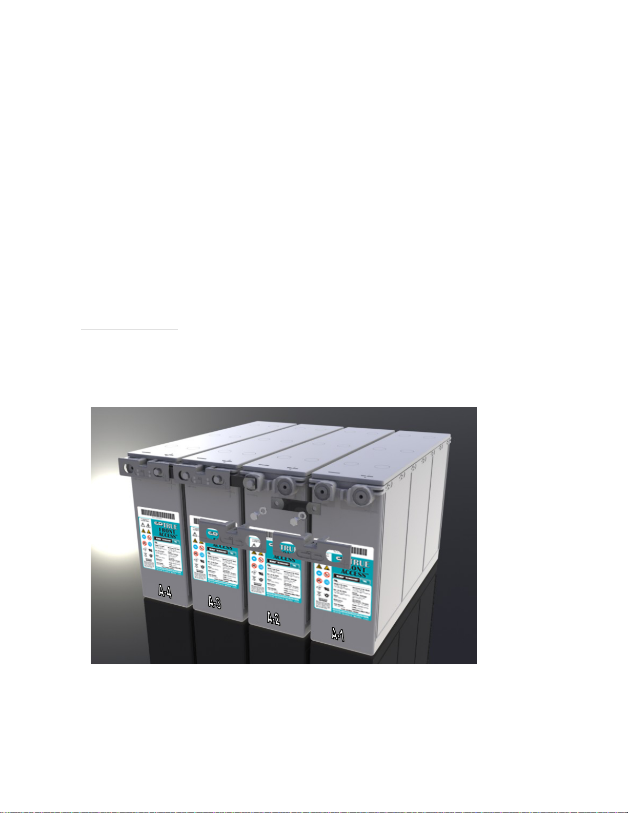
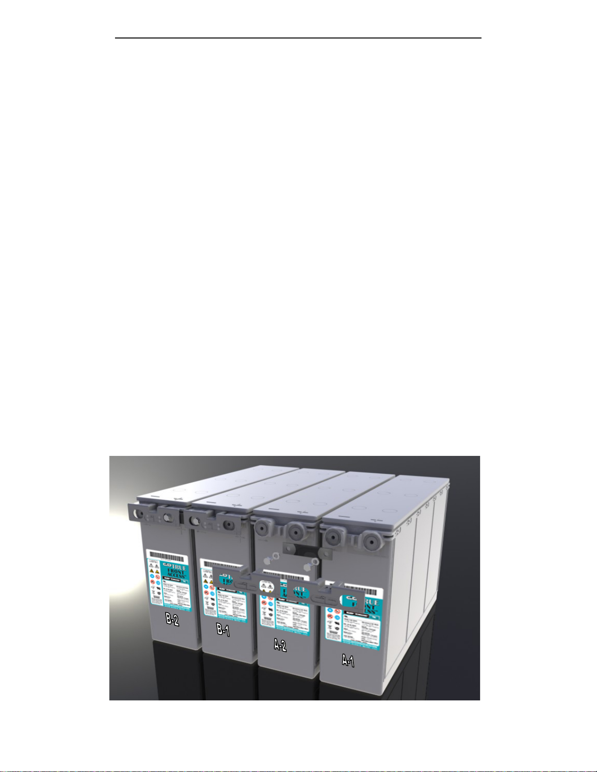
Step 4a. Starting at the battery on the far right of the tray/shelf, which is to be the positive (+) output, label it as
number 1 and then label the adjacent battery to the left as battery number two, string A. Repeat the numbering
procedure for the adjacent string (next two batteries to the left), string B.
Step 4b. If more than two 24 VDC strings is within the enclosure, number these batteries the same way.
Identify the bottom tray as string A and B with the strings above as string C and D and so on
Step 5. Using the provided inter-unit bus bar and hardware (bolt and washer), connect between String A,
battery 1’s negative (-) terminal to String A, battery 2’s positive (+) terminal as shown in Figure 5. Tighten bolt
washer assembly hand tight.
Step 6. Torque each of the above bolt washer assemblies as per the inch-pound specifications in Table 3 for the
appropriate product.
Step 7. Following the rack or cabinet manufacturers cabling guidelines to attach the lugged power lead
connections to positive (+) of String A, battery 1 and negative (-) of String A, battery 2 terminals verifying
proper polarities are observed.
Step 8. Torque each of the above bolt washer assemblies as per the inch-pound specifications in Table 3 for the
appropriate product.
Step 9. Repeat above steps for String B and each of any remaining battery strings.
Step 11. Install all protective terminal covers and use a utility knife or diagonal cutter to trim the cover as
needed allowing for proper cable routing.
Step 12. Verify charging equipment is set for proper float voltage of 2.25 to 2.30 volt per cell at 77°F at the
battery terminals (27 to 27.6 VDC for a nominal 24 volt battery).
.
Parallel Connection of individual strings of batteries
C&D recommends each individual battery string be cabled separately to a common junction point or box.
Each
string may also contain a separate fuse or disconnect switch
to facilitate maintenance. The parallel
connections should be completed
only when the charger and load are not
connected to the battery output
circuit or battery string voltage should be matched to within 0.5 volts before the connection is made and
should be performed only by qualified technicians familiar with live battery connections.
The battery
strings must not be ''daisy
chained'' in parallel.
RS02046/0514/CD 6 www.cdtechno.com

V. Optional
Gas Collection System Installation
(tubing kit PN 15028596)
TEL Series Models with ‘G’ in the product suffix (i.e. TEL12-105FNSG) include a gas collection system
feature which allows the hydrogen and oxygen gases that may vent from the battery to be directed to a
specific cabinet exit location by the installation of 6mm or ¼” ID PVC tubing. This tubing daisy chains
from one battery to the next in the string with the first battery in the string requiring a ‘plug’ in the hose
barb port above the positive terminal
of the battery (shown in Figure 6).
(Note that each battery ships with a
plug in this right side port. Installer
should remove any remaining plugs
to allow for tubing connection)
Individual tubes are cut by the
installer (each short tubing piece is
approx 6” in length) and are routed
from battery to battery as shown in
Figure 6 (please make sure that the
tubing is not kinked so gases can flow
freely in the tubing). A final system
collection tube, which varies in
length, is connected to the hose barb
port above the negative terminal on
the left most battery unit. This tube should be routed per the cabinet manufacturer’s instructions.
Special Note:
if the gas collection system is not required and/or utilized, the factory installed
plug in the right port of each 12 volt battery can be removed or can remain in place. NEVER
install a plug in both battery ports or the left side port since this will not allow the battery to vent
any excess pressure and could cause an unsafe condition.
VI. Freshening Charge
When the batteries have been in storage or transit for an extended period, over 6 months or if OCV’s are
below 12.48 volts or when the number of cells in series is greater than 24, it is recommended the battery
system be given a freshening charge at 2.4 volts average per cell for 24 hours prior to final installation.
This will ensure higher initial performance and will reduce the time period required for the cells to achieve
proper voltage balance between the individual units. Normally freshening charges are only necessary if batteries
were in a warehouse at 77°F in excess of 6 months or the open circuit voltage of the unit has declined to less than
12.48 VDC.
Additionally, if the batteries are being deployed into a system having a string voltage greater than 48Vdc,
C&D strongly recommends the entire string be given a 2.4 volts average per cell charge prior to
installation. This will ensure the closest possible voltage balance between the individual units in the
string.
VII. Float Charging
Following the freshening charge (if necessary) the battery
system should be placed on “float“ charge at
between 2.25 volts per cell and 2.30 volts per cell average (approximately 13.5 to 13.8 volts/unit
average
for 12 volt units at 77°F). When temperatures other than 77
°F (25°C) temperature compensated charging
may be needed.
Refer to technical bulletin 41-2128 “Charging Valve Regulated Lead Acid Batteries” for additional
information www/cdtechno.com/resource/support_doc.html
Plug
Short tubes
Tube to
cabinet
exit port
Figure 6 – Optional Gas Collection
System Installation (if required by
cabinet manufacturer)
RS02046/0514/CD 7 www.cdtechno.com

VIII. Initial Installation Data
The following initial installation data should be maintained on site:
•
Date and Initial open circuit voltage of unit(s) at time of delivery to the site.
•
Freshening charge records, if performed.
•
Initial torque value used for connections.
•
Overall system float voltage across battery terminals.
•
Individual unit float voltage.
•
Internal Ohmic value of each unit.
•
Connection resistances.
•
Float current.
IX. Periodic Maintenance
These VRLA batteries are maintenance free with respect to the electrolyte. However, the charging voltage,
temperature, performance and connection resistances must be periodically monitored and any necessary
corrective actions taken if irregular values are observed to assure reliable standby power when
required.
Quarterly Inspection
•
Measure and record the system total float charging voltage at the battery terminals
•
Record the charger on charge output current and voltage
•
Record the ambient temperature and condition of ventilation equipment
•
Visually inspect the batteries and rack for general appearance, cleanliness or any irregularity.
•
If gas tubing provisions are utilized, check for any obstructions in the tubing which would prevent
the free flow of gases thru the exit point.
Semiannual Inspection
•
Repeat the quarterly checks
•
Record the on charge voltage of each unit
•
Optionally perform and record Ohmic checks for trending purposes
Yearly and Initial Inspection
•
Repeat the semiannual checks
•
Inspect all connections to ensure integrity.
Any data, descriptions or specifications presented herein are subject to revision by
C&D Technologies, Inc. without notice. While such information is believed to be accurate
as indicated herein, C&D Technologies, Inc. makes no warranty and hereby disclaims all
warranties, express or implied, with regard to the accuracy or completeness of such
information. Further, because the product(s) featured herein may be used under
conditions beyond its control, C&D Technologies, Inc. hereby disclaims all warranties,
either express or implied, concerning the fitness or suitability of such product(s) for any
particular use or in any specific application or arising from any course of dealing or usage
of trade. The user is solely responsible for determining the suitability of the product(s)
featured herein for user’s intended purpose and in user’s specific application.
Copyright 2014C&D TECHNOLOGIES, INC. Printed in U.S.A. RS-2046 0514/CD
1400 Union Meeting Road
P.O. Box 3053 • Blue Bell, PA 19422-0858
(215) 619-2700 • Fax (215) 619-7899 • (800) 543-8630
customersvc@cdtechno.com
www.cdtechno.com
Other manuals for TEL Series
1
This manual suits for next models
18
Table of contents
Other C&D Technologies Camera Accessories manuals