Cannondale E440 2003 User manual

2003 Motorcycle Owner’s Manual
Models : E440, C440, X440, S440
P/N : 951-5002274-03
Before you operate the vehicle. . . .
• READ and UNDERSTAND this Owner’s Manual.
It contains information important to your safety.
• Learn the location and proper operation of all controls.
• Complete the Pre-Ride Inspection checklist.
• Wear appropriate protective gear - approved full faced helmet, eye
protection, gloves, boots, long-sleeve shirt, and pants.
Consider purchasing specially designed protective off-road vehicle
riding apparel.

© 2002 Cannondale Corporation - All Rights Reserved
2003 Motorcycle OM Cover.fm
IMPORTANT MANUAL INFORMATION
FAILURE TO FOLLOW THE WARNINGS CONTAINED IN THIS MANUAL CAN RESULT IN SERIOUS INJURY
OR DEATH.
Information important to your safety is distinguished in this manual by the following notations: \
The safety alert symbol means......
“ATTENTION! BECOME ALERT! YOUR SAFETY IS
INVOLVED.”
Indicates that DEATH or severe injury WILL result if the
instructions are not followed.
Indicates a potential hazard that could result in serious
injury or death.
A CAUTION indicates that special precautions must be
taken to avoid damage to the machine.
A NOTE provides helpful information intended to make
maintenance easier or the instructions presented clearer.
DANGER
WARNING
CAUTION:
NOTE:

3
Printed : 8/15/02
3
CONTENTS
IMPORTANT MANUAL INFORMATION- - - - - - - - - - - 2
FOREWORD - - - - - - - - - - - - - - - - - - - - - - - - 4
General Safety Precautions - - - - - - - - - - - - 5
Experienced riders only - - - - - - - - - - - - - - 7
Exercise good judgement- - - - - - - - - - - - - - 7
No Modifications - - - - - - - - - - - - - - - - - - 7
No passengers- - - - - - - - - - - - - - - - - - - 7
Inspection of Aluminum chassis components - - - - 8
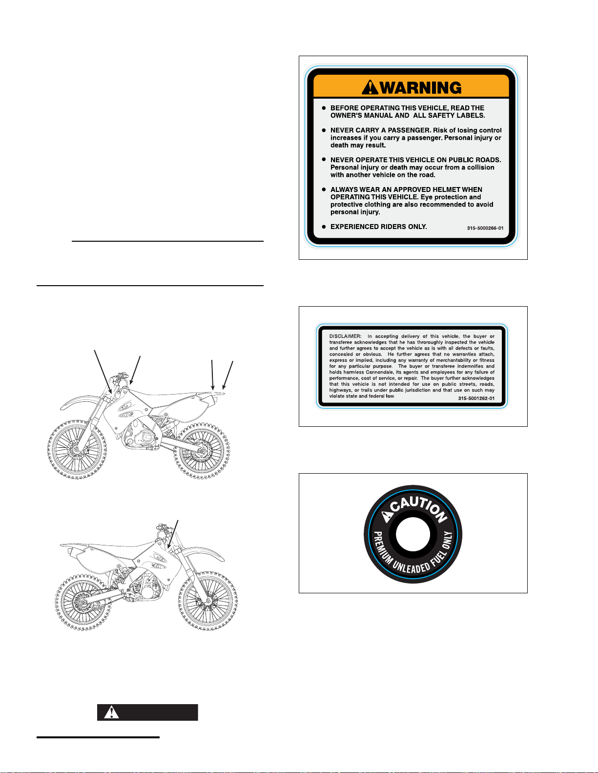
VEHICLE WARNING AND SPECIFICATION LABELS - - 10
VEHICLE IDENTIFICATION- - - - - - - - - - - - - - - - 12
Vehicle Identification Number (VIN)- - - - - - - - 12
Engine Serial Number - - - - - - - - - - - - - - 12
PARTS AND CONTROLS- - - - - - - - - - - - - - - - - 13
Engine start button - - - - - - - - - - - - - - - - 13
Engine ON/OFF Switch- - - - - - - - - - - - - - 14
Headlight and Taillight (USA) - - - - - - - - - - 14
lighting Option - - - - - - - - - - - - - - - - - - 15
Trip computer - - - - - - - - - - - - - - - - - - 15
Clutch lever - - - - - - - - - - - - - - - - - - - 16
Shift lever - - - - - - - - - - - - - - - - - - - - 16
Throttle Grip - - - - - - - - - - - - - - - - - - 16
Front brake lever - - - - - - - - - - - - - - - - - 18
Footpegs- - - - - - - - - - - - - - - - - - - - - 19
Rear brake pedal- - - - - - - - - - - - - - - - - 20
Side stand (or) kickstand- - - - - - - - - - - - - 21
Handguards - - - - - - - - - - - - - - - - - - - 23
Fuel tank cap - - - - - - - - - - - - - - - - - - 24
FLUIDS- - - - - - - - - - - - - - - - - - - - - - - - - - 24
Brake fluid - - - - - - - - - - - - - - - - - - - - 24
Coolant - - - - - - - - - - - - - - - - - - - - - 26
Engine oil - - - - - - - - - - - - - - - - - - - - 28
Hydraulic clutch fluid - - - - - - - - - - - - - - - 32
Fuel - - - - - - - - - - - - - - - - - - - - - - - 35
Transmission oil - - - - - - - - - - - - - - - - - 38
PRE-RIDE INSPECTION - - - - - - - - - - - - - - - - - 40
OPERATION - - - - - - - - - - - - - - - - - - - - - - - 42
Starting a warm engine- - - - - - - - - - - - - - 42
Jump starting - - - - - - - - - - - - - - - - - - 42
Shifting gears - - - - - - - - - - - - - - - - - - 43
Braking - - - - - - - - - - - - - - - - - - - - - 44
Post ride checks - - - - - - - - - - - - - - - - - 44
BREAK-IN - - - - - - - - - - - - - - - - - - - - - - - - 45
MAINTENANCE & ADJUSTMENT - - - - - - - - - - - - 46
Maintenance schedule - - - - - - - - - - - - - - 47
Seat - - - - - - - - - - - - - - - - - - - - - - - 49
Air filter- - - - - - - - - - - - - - - - - - - - - - 51
Brakes - - - - - - - - - - - - - - - - - - - - - - 53
Clutch - - - - - - - - - - - - - - - - - - - - - - 54
Drive - - - - - - - - - - - - - - - - - - - - - - - 54
Engine Management System - - - - - - - - - - - 61
Electrical - - - - - - - - - - - - - - - - - - - - - 62
Exhaust - - - - - - - - - - - - - - - - - - - - - 68
Fuel - - - - - - - - - - - - - - - - - - - - - - - 70
Steering - - - - - - - - - - - - - - - - - - - - - 73
Suspension- - - - - - - - - - - - - - - - - - - - 75
Adjustment - - - - - - - - - - - - - - - - - - - - 75
Tires - - - - - - - - - - - - - - - - - - - - - - - 87
Wheels- - - - - - - - - - - - - - - - - - - - - - 88
CLEANING - - - - - - - - - - - - - - - - - - - - - - - - 93
STORAGE - - - - - - - - - - - - - - - - - - - - - - - - 94
TIGHTENING TORQUES - - - - - - - - - - - - - - - - - 96
MAINTENANCE RECORD - - - - - - - - - - - - - - - - 97
SPECIFICATIONS - - - - - - - - - - - - - - - - - - - - 98
Service - - - - - - - - - - - - - - - - - - - - - 99
Suspension Settings - - - - - - - - - - - - - - 100
ADDENDA - - - - - - - - - - - - - - - - - - - - - - - -101
WARNING Indicates a potential hazard
that could result in serious
injury or death.
When reading this manual, remember:

© 2002 Cannondale Corporation - All Rights Reserved
4
2003 Motorcycle OM.fm
WARNING Indicates a potential hazard that could result in serious injury or death.
FOREWORD
This Owner’s Manual has been written carefully to provide you with a good basic understanding of all the features,
controls, proper operation, and maintenance of your vehicle. It also will provide you with important safety
information for you and anyone who operates it.
This manual should be considered a permanent part of the vehicle and it should remain with the vehicle whenever
it is resold or possession is transferred to another person. Please take the time necessary to read and understand
this entire owner’s manual.
Limitations
All information, illustrations, and specifications in this manual are based on the latest product information available
at the time of publication. Cannondale Corporation reserves the right to make changes at any time, without notice.
This vehicle has U.S. and International patents pending.
Comments
Send your comments or suggestions about this manual to: Technical Publications, Cannondale Corporation, 2 Cor-
porate Drive, Bedford, PA, 15522. Or, E-mail us at: technical.publications@cannondale.com.
IMPORTANT NOTICE
Some information in this manual may be outdated due to ongoing model improvements made
after the date of publication. The Addenda section at the end of this manual includes any addi-
tional, replacement, or supplemental information for your vehicle that is available at the time of
shipment.
You can download a Adobe PDF copy of this Owner’s Manual as well as any applicable
addenda, free of charge from our website. Go to: http://www.cannondale.com/motorsports/tech/
manuals.html,
Anytime you have any question related to the controls, features, or operation and maintenance of
your vehicle, please consult your Cannondale dealer. Or, call us at toll free at 1-800-MOTO-USA.

5
Printed : 8/15/02
5
GENERAL SAFETY PRECAUTIONS
DANGER
POTENTIAL HAZARD
Running the engine indoors
Breathing exhaust gases
WHAT CAN HAPPEN
Running the engine indoors will expose you
to dangerous exhaust gases. Breathing car-
bon monoxide gas leads to poisoning,
asphyxiation, and death. This will happen
rapidly and without notice.
HOW TO AVOID THE HAZARD
Never operate the vehicle indoors even for
brief periods of time.
WARNING
POTENTIAL HAZARD
Improper care when handling fuel
WHAT CAN HAPPEN
Fuel is highly flammable; spilling it can
cause a fire or explosion.
HOW TO AVOID THE HAZARD
Be sure the fuel cap is closed securely.
Work in a well-ventilated area which is free of
sources that could ignite any spilled fuel
accidentally (e.g. cigarettes, welders,
torches, grinders, electric shop tools, etc.)

© 2002 Cannondale Corporation - All Rights Reserved
6
2003 Motorcycle OM.fm
WARNING Indicates a potential hazard that could result in serious injury or death.
WARNING
POTENTIAL HAZARD
Hot components (e.g., engine, radiator,
hoses, bulbs, exhaust, brakes)
WHAT CAN HAPPEN
The engine and other vehicle systems oper-
ate at extremely high temperatures. Contact
can produce severe burns.
HOW TO AVOID THE HAZARD
Wait for the engine and vehicle systems to
cool completely before starting any work. If
the engine must be running, work carefully
and avoid hot surfaces.
WARNING
POTENTIAL HAZARD
Blindness, eye injury
WHAT CAN HAPPEN
Anytime you work on the vehicle there is a
potential that an accident involving a foreign
object, vehicle component part, fluid, tool, or
other maintenance related item can result in
severe injury to your eyes. For example,
when cleaning the oil filters, objects pro-
pelled by compressed air can strike your
eyes and cause serious injury or blindness.
HOW TO AVOID THE HAZARD
Always wear safety glasses when working on
the vehicle.

7
Printed : 8/15/02
7
EXPERIENCED RIDERS ONLY
This vehicle is not for beginners.
All Cannondale motorsports products are designed
for use by trained and experienced riders only. All are
very high performance, competition sport machines
and should only be operated by licensed competition
riders in excellent physical condition, who are well-
trained and experienced in the operation of high per-
formance competition vehicles.
EXERCISE GOOD JUDGEMENT
There is always risk involved when riding a vehicle;
however, making sure you and the vehicle are in the
best condition possible will ensure a great riding
experience. Use sound judgement when riding.
Never ride under the influence of alcohol, some over-
the-counter medications (read the product label), or
drugs. Doing so will greatly reduce your ability to
properly operate this vehicle and could lead to an
accident, injury, and/or death. If you are taking pre-
scribed medications, consult your doctor before
riding.
NO MODIFICATIONS
We recommend that you do not substitute parts,
change or modify your vehicle. Such changes could
seriously impair your vehicle’s handling, stability, and
braking, making it unsafe to ride and causing serious
injury and/or vehicle damage.
NO PASSENGERS
Do not overload this vehicle or carry passengers.
Doing so could seriously impair your vehicle’s han-
dling, stability, and braking, making it unsafe to ride
which could result in damage to the vehicle or
serious injury or death to the operator and/or pas-
senger.
WARNING
POTENTIAL HAZARD
Entanglement
WHAT CAN HAPPEN
Moving parts can catch your clothing, fin-
gers or hand resulting in severe injury.
HOW TO AVOID THE HAZARD
Never perform maintenance procedures with
the engine running unless otherwise
directed in a procedure.
WARNING
POTENTIAL HAZARD
Fluids
WHAT CAN HAPPEN
The fluids (engine/transmission oils, brake
fluid, coolant) in your vehicle are hazardous
substances. Contact with your skin or eyes
can result in serious injury or irritation.
If they are swallowed, severe injury or death
can result.
HOW TO AVOID THE HAZARD
Wear hand and eye protection (rubber gloves
and safety glasses or face shield) when
working with vehicle fluids. If a fluid gets on
your hands or clothing, wash it off immedi-
ately with soap and water. If swallowed seek
immediate medical attention.
KEEP ALL VEHICLE FLUIDS AWAY FROM
CHILDREN AND ANIMALS.

© 2002 Cannondale Corporation - All Rights Reserved
8
2003 Motorcycle OM.fm
WARNING Indicates a potential hazard that could result in serious injury or death.
INSPECTION OF ALUMINUM CHASSIS
COMPONENTS
The aluminum chassis components of your vehicle
have a finite, limited, useful life. The length of that life
varies depending on the material used in their manu-
facture, the amount of use they are subjected to, and
the care they receive while in service. Regular
inspection by a Cannondale Motorsports Dealer is
important.
• Frame - a main support structure for the engine,
various components, and rider.
• Subframe - adds structural support.
• Swingarm - a suspension component
Use in competitive events, hard and aggressive
riding, riding on severe terrain, riding in severe cli-
mates, and riding fast can dramatically shorten the
life of the aluminum (frame) components. Any one
and/or a combination of these conditions may result
in an unpredictable failure.
We recommend that you carefully inspect your
vehicle’s chassis components for cracking, bending,
deep scratches and/or other damage before every
ride.
If you have crashed or rolled your vehicle, there
could be damage hidden from your view. DO NOT
ride a vehicle with any crack, even a small one. It
must be carefully inspected by an authorized Can-
nondale Motorsports Dealer before it is operated
again.
Riding a cracked frame could lead to complete frame
failure. If you have any questions, contact your Can-
nondale dealer or call 1-800-MOTO-USA.
WARNING
POTENTIAL HAZARD(S)
(1) Riding on a cracked or damaged frame.
(2) Attempting to fix a damaged frame.
WHAT CAN HAPPEN
(1) Riding on a cracked or damaged frame
can lead to a complete frame failure.
(2) Aluminum frame (and components) are
heat treated. Welding, drilling, or modifying
the frame, subframe, or swingarm may
weaken the component and result in com-
plete failure, leading to a serious accident
with subsequent injury or death.
HOW TO AVOID THE HAZARD
Inspect carefully before riding.
Don’t ride on a cracked or damaged frame.
Don’t try to repair the frame, subframe, swin-
garm, or other components.
Have your Cannondale dealer inspect the
frame at every visit and at the 25 hour main-
tenance interval.
Call 1-800-MOTO-USA with any questions.

9
Printed : 8/15/02
9
Inspect the frame (1), lower frame rails (2) and sub-
frame (3) for cracks, deep scratches, or other
damage. If any damage is found, contact an autho-
rized Cannondale Motorsports Dealer for servicing.
N
OTE :
The frame and subframe are shown removed from
the vehicle for clarity.
Inspect the swingarm for cracks, deep scratches, or
other damage.
Inspect the weldments (individual welded compo-
nents comprising the total swingarm) and fastener
fixtures for any sign of cracking or damage.
Place the vehicle on a stand with the rear wheel sus-
pended. The swingarm should move freely up and
down with no play side to side. If any damage to the
swingarm is detected, take corrective action before
riding. Contact an authorized Cannondale Motor-
sports dealer for servicing.
1. Frame
2. Lower frame rails
3. Subframe
(2)
(1)
(3)
1. Swingarm (shown removed for clarity)
(1)

© 2002 Cannondale Corporation - All Rights Reserved
10
2003 Motorcycle OM.fm
WARNING Indicates a potential hazard that could result in serious injury or death.
VEHICLE WARNING AND
SPECIFICATION LABELS
You and anyone else who operates your vehicle
must read and understand all of the labels. They
contain information for safe and proper operation.
• Do not remove the labels for any reason.
• If any label is missing, damaged, worn, or
becomes difficult to read, you can get free
replacements from Cannondale.
Contact us toll free at 1-800-MOTO-USA.
• Always replace labels in the proper location.
NOTE :
Part numbers are printed in the lower right corner
of every label. The part numbers are also printed
in this manual.
(1)
(5,6)
(2)
(3)
(4)
Label 1 P/N 315-5000266-01
Label 2 P/N 315-5001262-01
Label 3

11
Printed : 8/15/02
11
Label 4
Label 5
Label 6 P/N 315-6000477-01

© 2002 Cannondale Corporation - All Rights Reserved
12
2003 Motorcycle OM.fm
WARNING Indicates a potential hazard that could result in serious injury or death.
VEHICLE IDENTIFICATION
The identification numbers found on your vehicle
identify it from others of the same model type.
You may need the identification numbers when
ordering replacement parts, service information, or to
assist in theft investigation and recovery.
Record your vehicle identification numbers in the
spaces provided. Keep a copy of the numbers in
another location.
NOTE :
Your vehicle may differ from those shown in the
illustrations in this manual.
VEHICLE IDENTIFICATION NUMBER
(VIN)
The vehicle identification number (VIN) is located on
the left side of the steering head.
ENGINE SERIAL NUMBER
The engine serial number is etched/stamped into the
rear area of the engine crankcase. The number also
appears on a temporary, factory-applied, adhesive
label in the same area.
1. Vehicle identification number
Record here
1
xxxxxxxxxxxxx
1. Engine serial number
Record here
XXXXXXXXXXXX
XXXXXXXXXXXX

13
Printed : 8/15/02
13
PARTS AND CONTROLS
This section contains information about the controls
and component features of your vehicle.
N
OTE :
This section may contain information about
controls and features not present on your
particular model.
The right and left sides of the vehicle are
determined by the operator’s left/right orientation
while seated on the vehicle facing forward in the
operating position.
ENGINE START BUTTON
The engine start button is located on the right han-
dlebar and is (GREEN) in color.
Press and release it without cranking over the engine
to activate the engine management system circuits.
Press and hold it to activate the starter motor.
Be sure to read the Operation section of this manual
for a detailed explanation of the best starting pro-
cedure.
N
OTE :
When cranking the engine, hold the button for no
more than 2-3 seconds at a time.
IMPORTANT NOTICE
Your vehicle may be equipped with optional
or special components (e.g., suspension,
steering, or handlebar controls) depending
on the model you purchased.
Consult the supplemental manufacturer’s
information about those components pro-
vided to you at the time of sale before oper-
ating or servicing the component or the
related system.
You can obtain Adobe PDF copies of all
owner’s manuals at our website. Go to:
http://www.cannondale.com/motorsports/
tech/manuals.html,
Anytime you have any question related
to the available manual supplements,
controls, features, or operation and
maintenance of your vehicle, please
consult your Cannondale dealer. Or, call
us at toll free at 1-800-MOTO-USA.
1. Engine start button
(1)
1

© 2002 Cannondale Corporation - All Rights Reserved
14
2003 Motorcycle OM.fm
WARNING Indicates a potential hazard that could result in serious injury or death.
ENGINE ON/OFF SWITCH
The engine ON/OFF siwtch is located on the left han-
dlebar. It is a two position (ON and OFF) toggle
switch.
Press “ON” to enable the engine management cir-
cuits.
Press “OFF” to disable the engine management cir-
cuits to shut down a running engine normally (fin-
ished riding). Press ‘OFF’ to stop a running engine in
the event of an emergency such as when the motor-
cycle overturns or throttle cable is stuck.
Test the switch before operating. Start the engine
and press OFF; if the engine does not shut down
immediately, do not ride the motorcycle; contact an
Cannondale motorsports dealer and have the switch
fixed.
HEADLIGHT AND TAILLIGHT (USA)
The headlight and taillight on equipped vehicles are
activated by the three position toggle switch mounted
on the center of the handlebar. The taillight should
turn on with the headlight when the switch is in either
the HI or LO headlight switch position. When the
switch is in the center position both lights should be
off.
Make sure the headlight and taillight operate properly
before starting out
1. ON/OFF switch
1
1. Headlight
2. Mounting straps (left fork)
3. Headlight/Taillight switch
1. Taillight
1
2
3
1

15
Printed : 8/15/02
15
If either headlight or taillight does not light, check to
see if a fuse or bulb replacement is needed. .
N
OTE :
Switch the lights off before attempting to start the
engine.
Be sure to return the switch to the center position
when the lighting is not required.
LIGHTING OPTION
Your vehicle may have optional lighting power takeoff
connector. This connector can be used to install
approved lighting systems. The connection for
optional lighting is located under the seat near the
main fuse and engine management system relay.
Do not improvise; contact your Cannondale Motor-
sports dealer to install the optional lighting system.
TRIP COMPUTER
A trip computer is located in the center of the han-
dlebar.
1. Lighting switch
WARNING
POTENTIAL HAZARD
Removing your hands from the handlebar
when operating
WHAT CAN HAPPEN
You can lose control of the vehicle and have
a serious accident.
HOW TO AVOID THE HAZARD
Select HI or LO intensity before moving off to
ride. Do not remove your hands from the
handlebar to toggle the switch while the
vehicle is moving. You could lose control
and have an accident.
1
1. Optional lighting tap (non-fused)
2. Main fuse
3. Engine Management System power relay
1. Trip computer
1
2
3
1

© 2002 Cannondale Corporation - All Rights Reserved
16
2003 Motorcycle OM.fm
WARNING Indicates a potential hazard that could result in serious injury or death.
Consult the Manufacturer’s Instruction Manual for the
unit features and operating instructions.
CLUTCH LEVER
The clutch lever is located on the left side of the han-
dlebar.
Pull in the clutch lever (quickly) to disengage the
clutch, and release the lever (slowly) to engage the
clutch.
The lever position can be adjusted so that the lever is
closer or further from the grip to suit for individual
hand sizes. To adjust the lever position, see the
Maintenance and Adjustment section of this manual.
SHIFT LEVER
The shift lever is located on the left side of the engine
just in front of the left footpeg.
The transmission has five gears, “one down, four up.”
Neutral is located between first and second gears.
THROTTLE GRIP
The throttle lever is located on the right handlebar
and controls acceleration and deceleration of the
engine.
WARNING
POTENTIAL HAZARD
Removing your hands from the handlebar
when operating
WHAT CAN HAPPEN
You can lose control of the vehicle and have
a serious accident.
HOW TO AVOID THE HAZARD
Make adjustments and settings before mov-
ing off to ride.
Always stop the vehicle on level ground
before operating (programming/setting) the
computer.
1. Clutch lever
2. Clutch reservoir
3. Lever position adjuster
3
2
1
1. Shift lever
Throttle freeplay: 1/8 - 5/16 in (3 - 8 mm)
1. Throttle grip
a. Freeplay
b. Open throttle (accelerate)
c. Close throttle (decelerate)
(1)
(b) (c)
(1)
(a)

17
Printed : 8/15/02
17
To accelerate the engine, rotate the grip towards you.
To decelerate the engine, turn the grip away from
you. When released the grip should spring back to
the idle position automatically.
Do the following before every ride:
Check the freeplay. Make sure the specified freeplay
is available in all handlebar positions. Adjust the
freeplay if necessary.
With the engine off, rotate the throttle from smaller to
larger openings and release the throttle. It should
close automatically to the idle position when release
at all positions and handlebar positions. It should
operat freely (e.g., without binding, dragging, or
sticking) and return to the closed position automati-
cally in all steering positions.
Adjusting the throttle freeplay
1. To adjust the freeplay, slide boot back to expose
lock ring and adjuster.
2. Loosen the lock ring, and turn the adjuster until
the specified freeplay is reached.
3. Tighten the lock ring securely, when finished, and
return the boot.
N
OTE :
If the throttle can not be adjusted further and the
freeplay is still out of specification, consult an
authorized Cannondale Motorsports Dealer.
WARNING
POTENTIAL HAZARD(S)
(1) Stuck or damaged throttle
(2) Incorrect freeplay
WHAT CAN HAPPEN
(1) The throttle must return to the closed
position automatically when you release it. If
it sticks, you can lose the ability to acceler-
ate and decelerate the engine which could
result in an accident where you could be
seriously injured or killed.
(2) The throttle freeplay must be maintained
as specified, otherwise the engine speed
could increase when the handlebars are
turned or when the throttle is slightly
grasped. Either situation could result in an
unexpected acceleration of the engine where
you could be seriously injured or killed.
HOW TO AVOID THE HAZARD
(1) Test the operation of the throttle before
each ride. Make sure it operates smoothly
(with no sticking or binding) in all steering
positions. It should return automatically to
the closed position when released.
(2) Make sure the throttle freeplay is adjusted
as specified.
(1 & 2) If the throttle malfunctions or you can
not adjust the throttle to the specified free-
play, do not ride the vehicle. Contact an
authorized Cannondale Motorsports Dealer
for servicing.
1. Long rubber boot
2. Cable adjuster
3. Lock ring
a. Decrease freeplay
b. Increase freeplay
(1) (a)
(b)
(2)
(3)

© 2002 Cannondale Corporation - All Rights Reserved
18
2003 Motorcycle OM.fm
WARNING Indicates a potential hazard that could result in serious injury or death.
FRONT BRAKE LEVER
The front brake lever is located on the right han-
dlebar. Pull it against the grip to apply the front
brakes.
Always make sure the brakes (front and rear) on
your vehicle operate properly before riding.
Measure the freeplay before you ride. Adjust the
freeplay if it is out of specification.
The position of the brake lever on the handlebar can
be adjusted so that control is comfortably positioned
to the operator’s preference.
Adjusting the front brake lever freeplay
Freeplay is the free travel distance required before
hydraulic pressure forces the brake pads to press
against the brake discs. The minimum freeplay is
required so that the lever can move as the rider
shifts hand position without resulting in pressure (as
detected in resistance in the lever) causing the brake
pads to press against the brake discs prematurely.
To measure the freeplay, roll the vehicle back and
forthwhile squeezing the lever lightly to detect the
fluid pressure point. The pressure point is indicated
when the brake pads start to press against the brake
disc applying braking force. Measure the distance
the lever moved at the end of the lever.
CAUTION:
Make sure the minimum freeplay of .12 in (3
mm) is available. Incorrect freeplay can result
in unintended pressure application in brake
system. The brake system can over overheat
damaging the pads or discs.
1. To adjust, loosen the the locknut.
2. Turning the adjustment screw.
3. Tighten the locknut to 4.3 lbf•ft (5.8 N•m).
Front brake lever freeplay:
0.12 - 0.8 in (3 - 20 mm)
1. Front brake lever
2. Freeplay
(a)
(1)
1. Locknut
2. Adjuster
a. Decrease freeplay
b. Increase freeplay
(b) (a)
(2)
(1)
(3)
0.12-0.8in
(3-20mm)

19
Printed : 8/15/02
19
Adjusting the front brake lever position
To adjust the front brake lever position on the han-
dlebar, loosen the clamp bolts and rotate the brake
lever to the desired position. Tighten the bolts to 5.0
lbf•ft (6.8 N•m) when finished. Tighten the upper bolt
to the specified torque, then tighten the lower bolt.
Front brake lever lubrication
1. Place the vehicle on a stand.
2. Remove the rubber cover from the brake lever.
3. Remove the nut (1), pivot bolt (2), and brake
lever (3).
4. Spray all the parts with a water-displacement
chemical, wipe them off, and dry them thor-
oughly.
5. Install the brake lever, and apply a light coat of
high quality waterproof grease onto the pivot
bolt.
N
OTE :
Only apply a light coat of grease so it does not
attract a lot of dirt and debris.
6. Install the pivot bolt and tighten the nut securely.
7. Install the rubber boot over the brake lever.
FOOTPEGS
The right and left footpegs on your vehicle should be
fastened securely and free of any collected mud or
dirt. The footpegs should move freely (up and down
on the pivot) and not bind - springing back when
released.
N
OTE :
After cleaning, lubricate the footpeg pivot points
with clean engine oil. Move the pegs up and down
to work the lubricant in.
Don’t use grease; grease will catch and collect dirt
and small particles which will damage the pivot
point. Make sure the teeth are in good condition
1. Upper bolt
2. Lower bolt
1. Nut
2. Pivot bolt
3. Brake lever
(1)
(2)
1
2
3
1. Footpeg (left)
2. Pivot
3. Spring
4. Teeth
1
3
2
4

© 2002 Cannondale Corporation - All Rights Reserved
20
2003 Motorcycle OM.fm
WARNING Indicates a potential hazard that could result in serious injury or death.
REAR BRAKE PEDAL
The rear brake pedal is located on the right side of
the vehicle.
Press it firmly with your foot to apply the rear brake.
Test to make sure it is operating correctly before you
ride. When pressed, braking force should be applied
to the rear brake disc. Braking force will increase the
more you press down on the pedal.
The rear brake pedal height can be adjusted for
comfort. To adjust it, see the Maintenance and
Adjustment section of this manual.
NOTE :
After cleaning, be sure to lubricate the pedal pivot
point with clean engine oil. It is not necessary to
remove the bolt, simply apply a few drops of oil to
the bolt and work the pedal up and down.
Adjusting the rear brake pedal height
1. Loosen the locknut on the master cylinder push-
rod. Turn the hex on top of the pushrod until the
brake pedal is at the correct height.
Turning the hex in direction (a) will lower the
brake pedal and turning the hex in direction (b)
will raise the pedal.
2. Tighten the locknut to 13.0 lbf•ft (17.6 N•m)
CAUTION:
When adjusting the brake pedal, make sure that
clearance (a) between the lower end of the
pushrod (1) and the brake pedal (2) is within
specification.
When raising the brake pedal, do not allow the
lower end of the pushrod thread to enter into
the brake pedal joint.
1. Rear brake pedal
2. Pivot
a. Pedal height
1
a
2
1. Locknut
2. Hex
a. Lowers the brake pedal
b. Raises the brake pedal
1. Pushrod
2. Brake pedal
a. Clearance 0.04 in (1mm)
(a) (b)
(1)
(2)
(1)
(a)
(2)
This manual suits for next models
3
Table of contents
Other Cannondale Motorcycle manuals