Canon ZR100 User manual

Canon
Z-~100
PUB.DIM-661
Digital
Video
Camcorder
II
Instruction Manual English
Camescope
numerique
II
Manuel d'instruction
Fran~ais
Videocamara
digital
Manual de Instrucciones 1Espanoll
MiniD;
.......
Digital
Video
Cassette

Important
Usage
Instructions
WARNING!
TO REDUCE THE RISK OF FIRE OR ELECTRIC SHOCK, DO NOT EXPOSE THIS
Lh
PRODUCT TO RAIN
OR
MOISTURE.
WARNING!
TO REDUCE THE RISK OF ELECTRIC SHOCK AND TO REDUCE ANNOYING
Lh
INTERFERENCE, USE
THE
RECOMMENDED ACCESSORIES
ONLY.
COPYRIGHT WARNING:
Unauthorized recording of copyrighted materials may infringe on the rights of
copyright owners and be contrary to copyright laws.
Digital Video Camcorder, ZR100 systems
This device complies with Part 15 of the FCC Rules. Operation
is
subject to the following two conditions: (1)
This device may not cause harmful interference, and (2) this device must accept any interference received,
including interference that may cause undesired operation.
Note: This equipment has been tested and found to comply with the limits for class Bdigital device, pursuant
to Part
15
of
the FCC Rules. These limits are designed to provide reasonable protection against harmful
interference
in
aresidential installation. This equipment generates, uses and can radiate radio frequency
energy and,
if
not installed and use
in
accordance with the instructions, may cause harmful interference to
radio communications. However, there is
no
guarantee that interference will not occur
in
aparticular
installation. Ifthis equipment does cause harmful interference to radio
or
television reception, which can
be
determined by turning the equipment off and on, the user is encouraged to try to correct the interference by
one or more
of
the following measures:
•Reorient or relocate the receiving antenna.
•Increase the separation between the equipment and receiver.
•Connect the equipment into an outlet on acircuit different from that to which the receiver
is
connected.
•Consult the dealer
or
an
experienced radiorrV technician for help.
Use
of
shielded cable is required to comply with class Blimits
in
Subpart B
of
Part 15 of FCC Rules.
Do not make any changes or modifications
to
the equipment unless otherwise specified
in
the manual.
If such changes
or
modifications should be made, you could be required to stop operation
of
the equipment.
Canon U.S.A. Inc,
One Canon Plaza, Lake Success, NY 11042, U,S,A.
Tel
No. (516)328-5600
CAUTION:
TO PREVENT ELECTRIC SHOCK, MATCH WIDE BLADE OF PLUG TO WIDE SLOT,
FULLY INSERT.
2
Important Warning
I-"'''W''~-l
Lh
RtSKOFELECTRICSI10C:K
DO
NOTOPE.N
CAUTION:
TO REDUCE THE RISK OF ELECTRIC
SHOCK, DO NOT REMOVE COVER (OR
BACK). NO USER-SERVICEABLE PARTS
INSIDE. REFER SERVICING TO
QUALIFIED SERVICE PERSONNEL.
The lightning flash with arrowhead symbol,
within an equilateral triangle,
is
intended to
alert the user
to
the presence of
uninsulated "dangerous voltage" within the
product's enclosure, that may
be
of
sufficient magnitude to constitute arisk of
electric shock
to
persons.
The exclamation point, within
an
equilateral triangle,
is
intended to alert the
user
to
the presence of important
operating and maintenance (servicing)
instructions
in
the literature accompanying
the product.

In
these safety instructions the word "product"
refers to the Canon Digital Video Camcorder
ZR100 Aand
all
its accessories.
1.
Read Instructions -All the safety and
operating instructions should be read
before the product is operated.
2.
Retain Instructions -The safety and
operating instructions should be retained
for future reference.
3.
Heed Warnings -All warnings on the
product and in the operating instructions
should
be
adhered to.
4.
Follow Instructions -All operating and
maintenance instructions should be
followed.
5.
Cleaning -Unplug this product from the
wall outlet before cleaning. Do not use
liquid or aerosol cleaners. The product
should
be
cleaned only as recommended
in
this manual.
6.
Accessories -Do not use accessories
not recommended
in
this manual as they
may
be
hazardous.
7.
Avoid magnetic
or
electric fields -Do not
use the camera close to
TV
transmitters,
portable communication devices or other
sources
of
electric
or
magnetic radiation.
They may cause picture interference, or
permanently damage the camera.
8.
Water and Moisture -Hazard
of
electric
shock -
Do
not use this product near
water or
in
rainy/moist situations.
9.
Placing or Moving -Do not place on an
unstable cart, stand, tripod, bracket or
table. The product may fall, causing
serious injury to achild or adult, and
serious damage to the
product.
Aproduct and cart
(I)
combination should
be
~
moved with care. Quick •
~
stops, excessive force,
~
and uneven surfaces may •
cause the product and cart
~w
combination to overturn.
10. Power Sources -The CA-570 Compact
Power Adapter should
be
operated only
from the type
of
power source indicated
on the marking label. If you are not sure
of
the type
of
power supply to your home,
consult your product dealer
or
local power
company. Regarding other power sources
such as battery power, refer to instructions
in
this manual.
11.
Polarization -The CA-570 Compact
Power Adapter
is
equipped with a
polarized 2-prong plug
(a
plug having one
blade wider than the other).
The 2-prong polarized plug will fit into the
poweroutlet only one way. This
is
asafety
feature. If you are unable to insert the plug
fUlly into the outlet, try reversing the plug. If
the plug still fails to fit, contact your
electrician to replace your obsolete outlet.
Do not defeat the safety purpose
of
the
polarized plug.
12. Power Cord Protection -Power cords
should be routed so that they are not likely
to be walked on or pinched by items
placed upon or against them. Pay
particular attention to plugs and the point
from which the cords exit the product.
13. Outdoor Antenna
Grounding-
If an
outside antenna is connected to the
product, be sure the antenna is grounded
so as to provide some protection against
voltage surges and built-up static charges.
Section 810
of
the National Electrical
Code, ANSI /NFPA No.
70-1984,
provides information with respect to
proper grounding
of
the mast and
supporting structure, grounding
of
the
lead-in wire to an antenna discharge unit,
size
of
grounding conductors, location
of
antenna discharge unit, connection to
grounding electrodes, and requirements
for the grounding electrode. See figure
1.
-
3

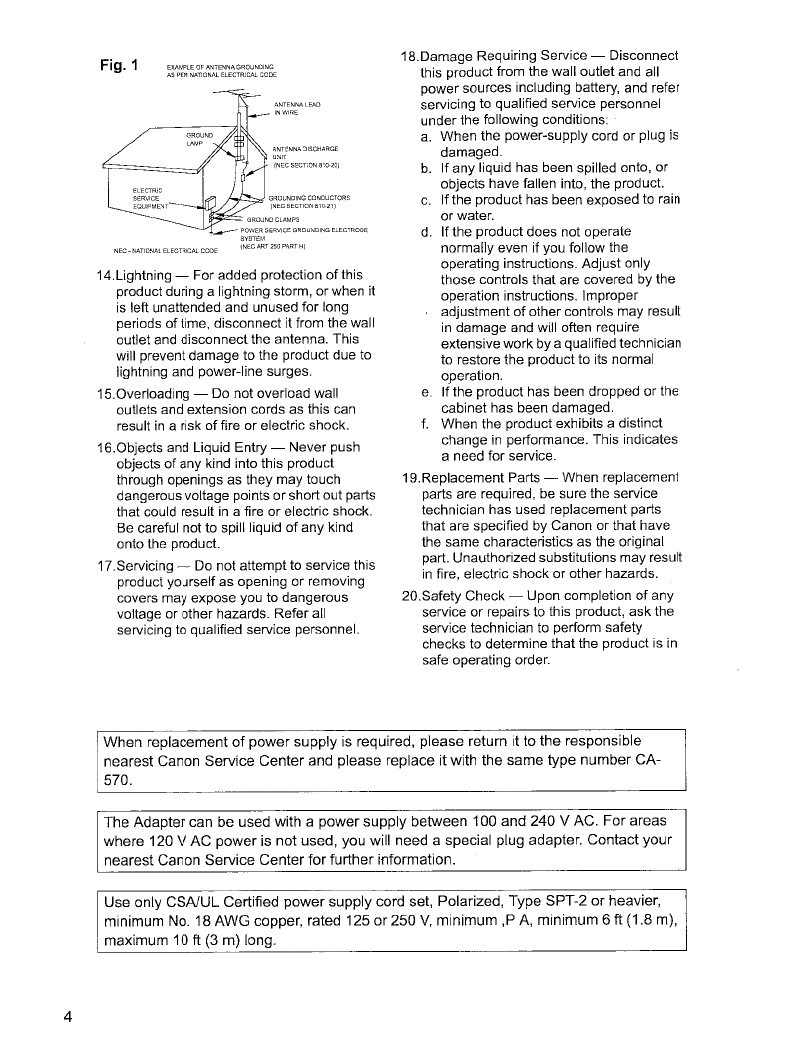
14.Lightning -For added protection
of
this
product during alightning storm, orwhen it
is
left unattended and unused for long
periods
of
time, disconnect it from the wall
outlet and disconnectthe antenna. This
will prevent damage to the product due to
lightning and power-line surges.
15.0verloading -Do not overload wall
outlets and extension cords as this can
result
in
arisk
of
fire
or
electric shock.
16.0bjects and Liquid Entry -Never push
objects
of
any kind into this product
through openings as they may touch
dangerous voltage points or short out parts
that could result
in
afire
or
electric shock.
Be careful not to spill liquid
of
any kind
onto the product.
17.Servicing -Do not attempt to service this
product yourself as opening or removing
covers may expose you to dangerous
voltage or other hazards. Refer all
servicing to qualified service personnel.
Fig.1
EXAMPLE OF ANTENNA, GROUNClING
AS PER NATIONAL ELECTRJCAL CODE
ANTENNA
LEAD
Ir-JWIRI;;
GROUNDING CONDUCTORS
(NECSECTIONB10-21)
18.Damage Requiring Service -Disconnect
this product from the wall outlet and all
power sources including battery, and refer
servicing to qualified service personnel
under the following conditions:
a.
When the power-supply cord or plug is
damaged.
b.
If any liqUid has been spilled onto, or
objects have fallen into, the
prodUCt.
c.
If the product has been exposed to rain
or
water.
d. If the product does not operate
normally even if you follow the
operating instructions. Adjust only
those controls that are covered by the
operation instructions. Improper
adjustment of other controls may result
in
damage and will often require
extensive workbyaqualified technician
to restore the product to its normal
operation.
e.
If
the product has been dropped
or
the
cabinet has been damaged.
f.
When the product exhibits adistinct
change
in
performance. This indicates
aneed for service.
19.Replacement Parts -When replacement
parts are required, be sure the service
technician has used replacement parts
that are specified by Canon or that have
the same characteristics as the original
part. Unauthorized substitutions may result
in
fire, electric shock
or
other hazards.
20.Safety Check -Upon completion
of
any
service or repairs to this product, ask the
service technician to perform safety
checks to determine that the product is
in
safe operating order.
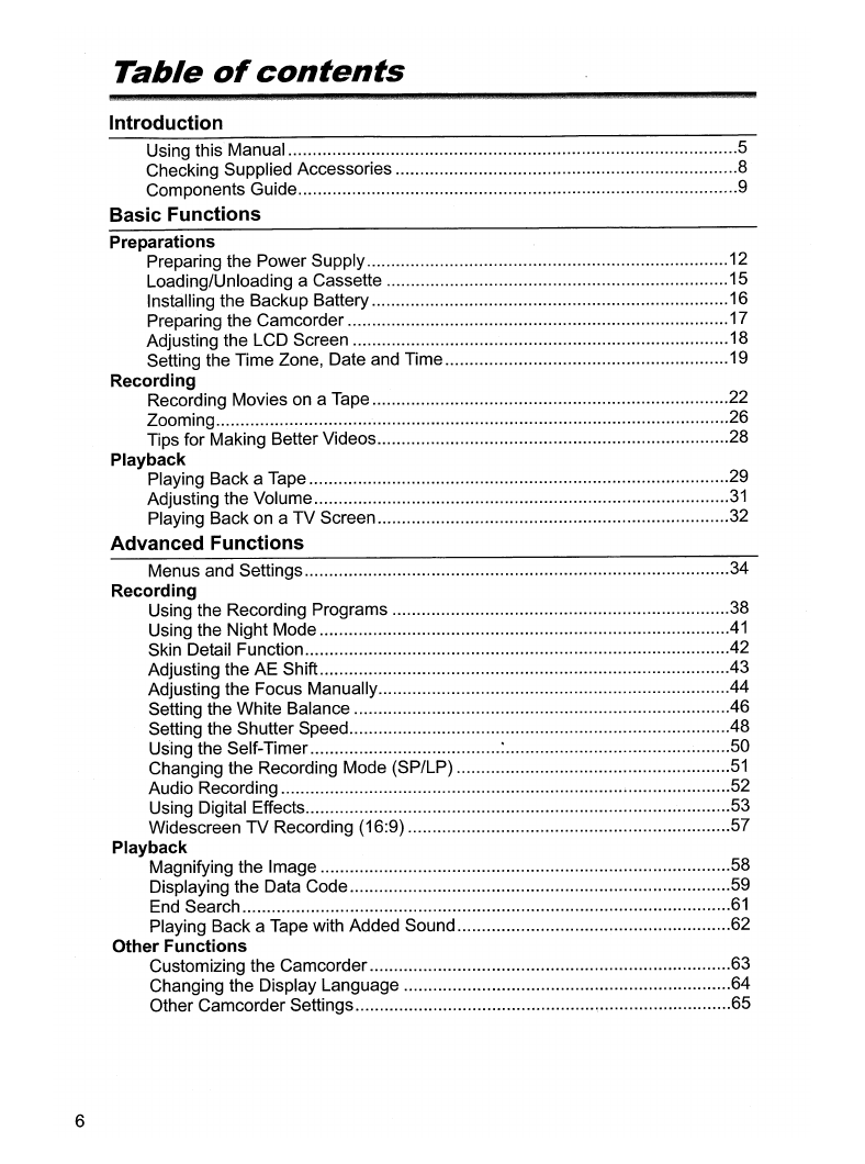
4
When replacement
of
power supply
is
required, please return it to the responsible
nearest Canon Service Center and please replace it with the same type number CA-
570.
The Adapter can
be
used with apower supply between 100 and 240 VAC. For areas
where 120 VAC power
is
not used, you will need aspecial plug adapter. Contact your
nearest Canon Service Center for further information.
Use only CSA/UL Certified power supply cord set, Polarized, Type SPT-2 or heavier,
minimum
No.
18 AWG copper, rated 125 or250
V,
minimum ,P
A,
minimum 6ft (1.8
m),
maximum
10ft
(3
m) long.

Using
this
Manual
Thank you for purchasing the Canon ZR100. Please read this manual carefully before
you use the camcorder and retain it for future reference.
Change the display language before you begin (OJ64).
S¥,mfb%QJi&wua;lJtdmBglf~il:eiIJAl«i~\&X%U!i&i~id{>iiL18u;Iib,ii&xxilWliiLllY·;'1iluyyu.
og :Precautions related to the camcorder operation.
o
II
:Additional topics that complement the basic operating procedures.
o
OJ
:Reference page number.
oCapital letters are used to refer to buttons
on
the camcorder.
o[] are used to refer to
.menu
items displayed on the screen.
o"Screen" refers to the LCD and the viewfinder screen.
Setting
the
Time
Zone,
Date
and
Time
Set the time zone, date and time when you first start using your camcorder,
or
when you
have replaced lhe backup batlery.
~.~tting
...
th~
...
Tim.~
....
ZQof#.P;:l.ylight
...
~;:l.vjngTjm~
,.
~~
::.s'-'
,;,,,.
""d
[SYSTEM]
,.,
"
...
"'I
,~,
I
3.
i~;~~h;
~;~
dial
to
select
[T.ZONEIDST]
and
press
...t~~
Thelimezoneseltingappears(seetableonlhenexlpage).The~===
defaullselting
is
New
York.
The operating modes are determined by the position
of
the POWER switch.
-
a
(3
c.
c
a
o'
::s
Operating Mode
CAMERA
PLAY (VCR)
POWER Switch
CAMERA
PLAY (VCR)
CAMERA
:Function can be used
in
this mode.
Trademark Acknowledgments
•
MiniDt....
is atrademark.
•Windows® is either aregistered trademark or trademark
of
Microsoft Corporation
in
the
United States and/or other countries.
•Macintosh and Mac OS are trademarks
of
Apple Computer, Inc., registered
in
the
United States and other countries.
•Other names and products not mentioned above may be registered trademarks or
trademarks
of
their respective companies.
5

6
Table
of
contents
Introduction
Using this Manual 5
Checking Supplied Accessories 8
Components Guide 9
Basic Functions
Preparations
Preparing the Power Supply 12
Loading/Unloading aCassette 15
Installing the Backup Battery 16
Preparing the Camcorder 17
Adjusting the LCD Screen 18
Setting the Time Zone, Date and Time 19
Recording
Recording Movies on aTape 22
Zooming 26
Tips for Making Better Videos 28
Playback
Playing Back aTape 29
Adjusting the Volume
31
Playing Back on aTV Screen 32
Advanced Functions
Menus and Settings 34
Recording
Using the Recording Programs 38
Using the Night Mode
41
Skin Detail Function 42
Adjusting the AE Shift 43
Adjusting the Focus Manually 44
Setting the White Balance 46
Setting the Shutter Speed 48
Using the Self-Timer :50
Changing the Recording Mode (SP/LP)
51
Audio Recording 52
Using Digital Effects 53
Widescreen TV Recording (16:9) 57
Playback
Magnifying the Image 58
Displaying the Data Code 59
End Search
61
Playing Back aTape with Added Sound 62
Other Functions
Customizing the Camcorder 63
Changing the Display Language 64
Other Camcorder Settings
~
65

Editing
Recording to aVCR or Digital Video Device 67
Recording from Analog Video Devices (VCR, TV or Camcorder) 69
Recording from Digital Video Devices (DV Dubbing) 70
Converting Analog Signals into Digital Signals (Analog-Digital Converter) 72
Transferring Video Recordings to aComputer 74
Additional Information
Screen Displays 75
List of Messages 77
Maintenance/Others 78
Troubleshooting 83
System Diagram (Availability differs from area to area) 86
Optional Accessories 87
Specifications 90
Item Codes '
92
Index 93 -
7

8
Checking
Supplied
Accessories
NB-2LH Battery Pack Lithium Button Battery Lens Cap and Lens
CR1616 Cap Cord
STV-250N Stereo
Video Cable
The serial number ofthis product can
be
found at the battery attachment unit
of
the
camcorder. Write down the number and other information here and retain this book as a
permanent record of your purchase to aid identification
in
case
of
theft.
Date
of
Purchase: Model Name: ZR100 A
Purchased From: Serial No.:
Dealer Address:
Dealer Phone No.:
®LAMP(S) INSIDE THIS PRODUCT CONTAIN MERCURY AND MUST BE
RECYCLED
OR
DISPOSED OF ACCORDING TO LOCAL, STATE
OR
FEDERAL LAWS.

Components
Guide
@------,.
CD
~@
REC
SEARCH
fOCUS
~\GI-\T
MOD~
') ®
I
~
5
@
-1~~EFFECTS
I®
I
LCD
BACKLIGHT
~
ON/OFF
(j)
®---~()
~AESHIFT/
I
_______
rl~EN
\"''zENDSEARCH
®
6ATACODE
q=-J
®-
CD
REC SEARCH -button
(CO
25) /
(9
(record review) button (
CO
25) /
~(rewind)
button
(CO
29)
@REC SEARCH +button
(CO
25) /
~
(fast forward) button
(CO
29)
®LCD BACKLIGHT button
(CO
18)
@WIDESCREEN button
(CO
57) /
DATA CODE button
(CO
59)
®NIGHT MODE button
(CO
41) /
•(stop) button
(CO
29)
®FOCUS button
(CO
44) /
~
/11(play/pause) button
(CO
29)
(j) DIGITAL EFFECTS ON/OFF button
(OJ 53)
®AE SHIFT button
(CO
43) /
END SEARCH button
(OJ
61)
®REC PAUSE button (OJ 69)
@Speaker
(CO
31)
@LCD screen
(CO
18)
©
SET
dial
(CO
34)
@
CHARGE
indicator
(CO
12)
@Program selector
(CO
38)
EASY
Easy recording
[E]
Program
AE
@Backup battery compartment (OJ ·16)
@Battery attachment unit
(CO
12) /
Serial
number
@DC
IN
terminal (OJ 12)
@MENU button (OJ 34)
9

r-----@
®
®
®
---
-ltfF'if
®--~--....
CD
Dioptric adjustment lever (OJ 17)
(J)
OPEN/EJECT
~
switch (OJ 15)
@Viewfinder (OJ 17) @Zoom lever (OJ 26)
®
BATT.
button (OJ 12) ®Finger rest
®Power switch (OJ 5)
®Cassette compartment cover (OJ 15)
®Cassette compartment (OJ 15)
@Strap mount (OJ 88)
@Grip belt (OJ 17)
@Start/stop button (OJ 22)
10

-
[
a
Q.
c
a
o'
:s
CD
Terminal cover
@Stereo microphone
®AV terminal (OJ 32)
@
DV
terminal (OJ 67)
®Tripod socket (OJ 28)
11

Preparing
the
Power
Supply
•
.PLAY(VCR)
••
·CAMERA
Iim'ID
1.
Turn
the
POWER
switch
to
OFF.
2.
Attach
the
battery
pack
to
the
camcorder.
•Remove the terminal cover
of
the battery
pack.
•Press lightly and slide it
in
the direction
of
the arrow until it clicks.
12
1.
Connect
the
power
cord
to
the
.adapter.
2.
Plug the
power
cord
into
a
power
outlet.
3.
Connect
the
power
adapter
to
the
camcorder's
DC
IN
terminal.
The CHARGE indicator starts flashing. It
glows steadily when charging is complete.
4.
When
charging
is
complete,
disconnect
the
power
adapter
from
the
.camcorder.
Unplug
the
power
cord
from
the
power
outlet
and
disconnect
it
from
the
adapter.
5.
Remove
the
battery
pack after use.
Press the BATT. button to remove the. battery.

Connect to ahousehold power source to use the camcorder without worrying about the
battery power.
You
can keep the battery pack attached; the battery power will not be
~E
consumed.
~
1.
Turn the POWER
switch
to
OFF.
2.
Connect
the
power
cord
to
the
power
adapter.
3.
Plug the
power
cord
into
a
power
outlet.
4.
Connect
the
power
adapter
to
the
camcorder's
DC
IN
terminal.
oTurn offthe camcorder before connecting or disconnecting the power adapter.
oIfthe adapter is used close to a
TV,
it may cause picture. interference. Move the
adapter away from the
TV
or the antenna cable.
oDo not connect any products that are not expressly recommended to the
camcorder's DC
IN
terminal or to the power adapter.
o
You
may hear some noise from the power adapter during use. This is not a
malfunction.
oDo not disconnect and reconnect the power cord while charging abattery pack.
Charging may stop. The battery pack may not be charged correctly even ifthe
CHARGE indicator glows steady. The battery pack may also not be charged
correctly when apower outage occurs during charging. Remove the battery
pack and attach it back to the camcorder.
oWhen the power adapter or battery pack is defective, the CHARGE indicator
flashes rapidly (at about 2flashes/second) and charging stops.
oThe CHARGE indicator informs you about the charge status.
0-50%: Flashes once every second
More than
500/0:
Flashes twice every second
1000/0:
Glows steadily
-
13

oCharging, Recording and Playback Times
Below times are approximate and vary according to the charging, recording or
playback conditions.
Battery Pack
Charging Time
Max. Recording Time
BP-2L14
235 min.
14
Viewfinder 135 min.
115
min. 245 min. 300 min.
LCD Inormal
95
min. 80 min. 170 min. 210 min.
Ibright
85
min.
70
min. 145 min. 185 min.
Typical RecordingTime*
Viewfinder
75
min. 60 min. 130 min. 160 min.
LCD Inormal
55
min. 45 min. 95 min. 120 min.
Ibright
50
min. 40 min. 85 min. 105 min.
Playback Time 100 min. 85 min. 175 min. 220 min.
*Approximate times for recording with repeated operations such as start'stop,
zooming, power on/off. Actual time may be shorter.
oWe recommend charging the battery pack
in
temperatures between
10°C
and
30
°C (50 of and 86
OF).
Outside the temperature range
of
a°C to
40°C
(32
OF
to 104
OF),
the CHARGE indicator flashes rapidly and charging stops.
oAlithium ion battery pack can
be
charged at any charge state. Unlike
conventional battery packs, you do not need to completely use or discharge it
before charging.
oWe recommend that you prepare battery packs 2to 3times longer than you
think you might need.
o
To
conserve battery power, turn offthe camcorder instead
of
leaving it
in
record
pause mode.

Loading/Unloading
a
Cassette
Use only videocassettes marked with the
M;';DtT
1.
Slide the OPEN/EJECT switch and
open the cassette compartment
cover.
The cassette compartment opens
automatically.
2.
Load/unload the cassette.
•Load the cassette with the window
facing the grip belt.
•Unload the cassette by pulling it straight
out.
3.
Press the
~
mark
on
the
cassette compartment until it
clicks.
4.
Wait for the cassette compartment
to retract automatically and close
the cassette compartment cover.
logo.
Tape protection tab
-
000
not·interfere with the cassette compartment while it is opening
or
closing
automatically, or attempt to close the cover before the cassette compartment
has fully retracted.
oBe careful not to get your fingers caught
in
the cassette compartment cover.
eI!
Ifthe camcorder is connected to apower source, cassettes can
be
loaded/
~
unloaded even ifthe POWER switch
is
set to OFF.
15

16
Installing
the
Backup
Battery
4¢
The backup battery (lithium button battery CR1616) allows the camcorder to retain date,
time
(CD
19) and other camcorder settings while the power source is disconnected.
Connect apower source to the camcorderwhen replacing the backup battery to retain the
settings.
1.
Open the backup battery cover.
2.
Insert the backup battery with the
+side facing outward.
........,
+t;J
G)
0-
L....t
3.
Close the cover.
f'&I!
The backup battery has alife span of about ayear. "
~
"flashes
in
red
to inform
~
you
that it needs to
be
replaced.

Preparing
the
Camcorder
$
24
~.(:Ij.Y.$ti.ng,
...
th@
...
·.\ligvdindg[.(tllQPl[tc.~.(:Ijy§.
trrlgnt)
1. Turn on
the
camcorder
and
keep
the
LCD panel closed.
2. Pull
out
the
viewfinder.
3.
Adjust
the
dioptric
adjustment
lever.
4. Push
the
viewfinder
back
in.
~ttc:lcbin.g.·.thg
..
L.gns.Cap
1. Attach the cord to
the
lens cap.
2.
Pass the grip belt
through
the
loop
on
the
cord.
Press the buttons on the lens cap when
attaching/removing
it
Hook the lens cap
on
the grip belt while you are recording,
and place it over the lens when you have
finished.
E.a$tgoing.·.·
..
thg
....
J~rip,
...
a.g.lt
Hold the
camcorder
with
your
right
hand and
adjust
the
belt with
your
left.
Adjust the grip belt so that you can reach the
zoom lever with your index finger, and the
start/stop button with your thumb.
-
17

18
Adjusting
the
LCD
Screen
Wl.
RQl"tit1g.thg,LCQ,S(;re~t1
....
Open the LCD panel 90 degrees.
•
You
can rotate the panel by
90
degrees
outward.
•
You
can rotate the panel by 180 degrees
inward.
You
can switch the brightness
of
the LCD screen between normal and bright by pressing
the LCD BACKLIGHT button. This
is
useful for outdoor recordings.
Press the LCD BACKLIGHT button.
oThis setting does not affect the brightness of the recording or the viewfinder
screen.
oWhen using abattery pack, the camcorder retains the setting even ifyou
change the position ofthe POWER switch.
oThe battery usage time shortens when the LCD screen is set brighter (OJ 14).

Setting
the
Time
Zone,
Date
and
Time
Set the time zone, date and time when you first start using your camcorder, or when you
r-;;-)
have replaced the backup battery.
~
CAMERA
PLAY (VCR)
-
I
~
:t~~
2.
Turn
the
SET dial
to
select
[SYSTEM] and
press
the
SET dial.
3.
Turn
the
SET dial
to
select
[T.ZONE/OST] and
press
the
SET dial.
The time zone setting appears (see table
on
the next page). The
default setting is New
York.
4.
Turn
the
SET
dial
to
select
the
setting
option
that
represents
your
time
zone
and
press
the
SET dial.
To
adjust for daylight saving time, select the time zone with the *next to the area.
~~~)
I
SYSTEM
IIl>I
T.ZONE/DST···N.Y.
1.
Press the MENU
button
to
open the menu.
CAMERA
PLAY (VCR)
I
~
D/TIME
SET···JAN. 1,2005
12:00
AM
L--
_
I
SYSTEM
MENU
(CD
34)
5.
Turn
the
SET
dial
to
select
[O/TIME SET]
and
press
the
SET dial.
The year display starts to flash.
6.
Turn
the
SET
dial
to
select
the
year, and
press
the
SET
dial
.
•The next part of the display starts flashing.
•Set the month, day, hours and minutes
in
the same
way,
19

7.
Press the MENU button to close the menu and to
start the clock.
[~
20
No.
Time zone No. Time zone
IT]
LONDON
0]
WELLGTN (Wellington)
~
PARIS
[H]
SAMOA
[]] CAIRO
[I§]
HONOLU. (Honolulu)
@1
MOSCOW
[ill
ANCHOR. (Anchorage)
ffi] DUBAI
BZl
L.A. (Los Angeles)
[ill KARACHI
[Im
DENVER
rn
DACCA
0]]
CHICAGO
[ID
BANGKOK
~
N.Y.
(New York)
ffil
H.
KONG (Hong Kong)
~
CARACAS
[1Q]
TOKYO
[ll]
RIO (Rio de Janeiro)
[ill SYDNEY
~
FERNAN. (Fernando de Noronha)
D1l
SOLOMON
~
AZORES
rail Once you have set time zone, date and time, you do not need to reset the clock
~
each time you travel to another time zone. Just set the time zone to the one
of
your destination, and the camcorder automatically adjusts the clock.
Other manuals for ZR100
2
Table of contents
Other Canon Camcorder manuals

Canon
Canon LEGRIA HFR86 User manual

Canon
Canon XM2 User manual

Canon
Canon MV5 User manual

Canon
Canon 3CCD User manual

Canon
Canon VIXIA HF M50 User manual

Canon
Canon XM2 User manual

Canon
Canon Auto Zoom 518 SV User manual

Canon
Canon Optura 200 MC User manual

Canon
Canon MVX300 User manual

Canon
Canon Legria HF R66 User manual

Canon
Canon A-1 User manual

Canon
Canon AF514XL-S Canosound User manual

Canon
Canon FS400 User manual

Canon
Canon LEGRIA HF G26 User manual

Canon
Canon VIXIA HFR60 User manual

Canon
Canon Vixia mini X User manual

Canon
Canon HV20 - VIXIA Camcorder - 1080i User manual

Canon
Canon FX 305 User manual

Canon
Canon VIXIA HR10 User manual

Canon
Canon Vixia mini X User manual