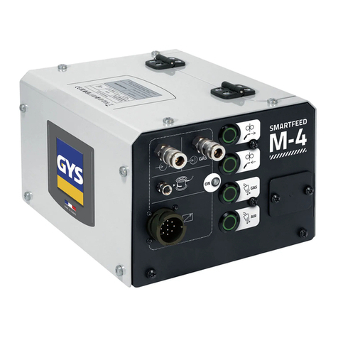
Canon DADF-G1 User manual

FY8-13GK-000
DADF-G1
REVISION 0
OCT. 2000
COPYRIGHT
©
2000 CANON INC. CANON DADF-G1 REV.0 OCT. 2000 PRINTED IN JAPAN (IMPRIME AU JAPON)
CLICK HERE FOR PARTS CATALOGUE


Scope of Application
This document is published by Canon Inc. for the purpose of providing individuals with the technical
knowledge needed to install, maintain, and repair the product under discussion. It may also be used as
a reference when studying the technical aspects of the product.
The contents of this document are generic in nature so as to cover all areas where the product is sold.
In this respect, it is important to note that some of the specifications or descriptions found in this
documentation may not apply in some areas.
In addition, it must be borne in mind that the specifications or descriptions may differ from those
noted in the actual machine or found in advertisements or in other printed matter.
All questions concerning this document are to be addressed to the Service Department of the
appropriate Sales Company.
Revision
The information disclosed in this document may not necessarily be accurate because of updates
made to the product, and major differences will be communicated in the form of technical bulletins.
The following will not apply where it does not conform to the laws or regulations of the country in which
the product is used.
Trademarks
The product names and company names found in this document are registered trade marks or trade
marks of their respective companies.
Copyright
The title to this document belongs to Canon Inc., and no part of it must be reproduced, quoted, or trans-
lated into another language without the consent of Canon Inc. in writing.
COPYRIGHT
©
2000 CANON INC. CANON DADF-G1 REV.0 OCT.2000
Warning
This document must be handled with utmost care. Disclosure of its contents may lead to legal proceedings.
COPYRIGHT © 2000 CANON INC.
Printed in Japan
Imprimé au Japon

COPYRIGHT
©
2000 CANON INC. CANON DADF-G1 REV.0 OCT. 2000
i
INTRODUCTION
1 Symbols Used
This documentation uses the following symbols to indicate special information:
Symbol Description
Indicates an item requiring care to avoid combustion (fire).
Indicates an item prohibiting disassembly to avoid electric shocks or problems.
Indicates an item requiring disconnection of the power plug from the electric
outlet.
Indicates an item intended to provide notes assisting the understanding of the
topic in question.
Memo
Indicates an item of reference assisting the understanding of the topic in ques-
tion.
REF.
Provides a description of a service mode.
Provides a description of the nature of an error indication.
Refers to the Copier Basics Series for a better understanding of the contents.
Indicates an item of a non-specific nature, possibly classified as Note, Caution,
or Warning.
Indicates an item requiring care to avoid electric shocks.

COPYRIGHT
©
2000 CANON INC. CANON DADF-G1 REV.0 OCT. 2000
ii
INTRODUCTION
2 Outline of the Sevice Manual
This Service Manual contains basic information needed to service the DADF-G1 in the
field, conducted for the purpose of maintaining its product quality and a specific level of
performance.
This Service Manual consists of the following chapters:
Chapter 1
General Description
shows the features and specifications of the machine,
as well as the names of parts and how to operate it.
Chapter 2
Operation and Timing
explains the mechanical and electrical systems of
the machine by function in relation to the principles of operation and timing
at which they are driven.
Chapter 3
Mechanical Systems
shows how to disassemble/assemble the machine and
make adjustments.
Chapter 4
Maintenance and Inspection
provides tables of periodically replaced
parts and consumables/durables and a scheduled servicing chart.
Chapter 5
Troubleshooting
shows standards to follow and adjustments to make, and
provides troubleshooting tables.
Appendix added to offer a general timing chart and PCB diagrams.
The machine comes with an Installation Procedure. Refer to the instructions in the book-
let when installing the machine.
The descriptions of the machine are subject to change for product improvement, and ma-
jor changes will be communicated in the form of Service Information bulletins.
All service persons are expected to be fully familiar with the contents of this Service
Manual and Service Information bulletins to develop a good understanding of the machine,
equipping themselves with the ability and skill to identify faults and to maintain the ma-
chine in good order.

COPYRIGHT
©
2000 CANON INC. CANON DADF-G1 REV.0 OCT. 2000
iii
CONTENTS
Contents
CHAPTER 1 GENERAL DESCRIPTION
1 Basic Construction ....................... 2-1
1.1 Outline of the Electrical
Circuitry ................................ 2-1
1.2 Communication withthe
Host copier ............................ 2-2
1.3 Inputs to the DADF
Controller PCB...................... 2-3
1.3.1 Inputs to the DADF
Controller PCB (1/2) ..... 2-3
1.3.2 Inputs to the DADF
Controller PCB (2/2) ..... 2-4
1.4 Outputs from the DADF
Controller PCB ..................... 2-5
1.4.1 Outputs from the DADF
Controller PCB (1/1) ..... 2-5
2 Basic Operations........................... 2-6
2.1 Outline .................................. 2-6
2.2 Operations ............................. 2-7
2.2.1 Single-Sided Original
Mode ............................. 2-7
2.2.2 Double-Sided Original
Mode ............................. 2-8
2.3 Detecting Originals ............... 2-9
2.3.1 Outline ........................... 2-9
2.3.2 Detecting the Presence/
Absence of an
Original ....................... 2-10
2.3.3 Detecting the Size of
Originals ...................... 2-10
2.3.4 Detecting the Trailing Edge
of the Last Original ..... 2-14
2.4 Picking Up Originals .......... 2-15
2.4.1 Outline ......................... 2-15
2.4.2 Pickup Operation......... 2-15
2.5 Reversing Originals ............ 2-19
2.5.1 Operations ................... 2-19
2.5.2 Sequence of Operations
(reversal)...................... 2-20
2.6 Delivery............................... 2-21
2.6.1 Outline ......................... 2-21
2.6.2 Delivery Operations .... 2-22
2.7 Controlling the Pickup
Motor .................................. 2-25
2.7.1 Outline ......................... 2-25
2.7.2 Relationship Between the
Pickup Roller and the
Pickup Motor Drive Signal
(SMON), Pickup Motor
Rotation Direction Signal
(SDIR), and Pickup Motor
Rotation Speed Control
Signal (SMPWM) ....... 2-26
2.8 Controlling the Belt
Motor .................................. 2-27
1 Features ........................................ 1-1
1.1 Identifying the Size of
Originals ............................... 1-1
2 Specifications ............................... 1-2
3 Names of Parts.............................. 1-4
3.1 External View........................ 1-4
3.2 Cross Section ........................ 1-4
4 Operating the Machine ................. 1-5
4.1 Original Set Indicator ........... 1-5
4.2 Warnings and Actions to
Take ....................................... 1-6
4.3 Routine Maintenance by
the User ................................. 1-6
4.3.1 Copyboard glass ............ 1-6
4.3.2 Feed Belt ........................ 1-6
4.3.3 Others ............................ 1-6
4.3.4 Separation Belt and Feed
Roller ............................. 1-6
CHAPTER 2 OPERATIONS AND TIMING

COPYRIGHT
©
2000 CANON INC. CANON DADF-G1 REV.0 OCT. 2000
iv
CONTENTS
2.8.1 Outline ......................... 2-27
2.8.2 RelationshipBetween the
Feed Belt and the Belt
Motor Drive Signal
(BMON), Belt Motor
Rotation Direction Signal
(BDIR), and Belt Motor
Rotation Speed Control
Signal (BMPWM) ....... 2-28
2.8.3 Protecting the Belt Motor
from Overcurrent......... 2-28
2.9 Detecting a Jam................... 2-29
2.10 Improperly Placed
Original ............................... 2-32
2.10.1 Resetting...................... 2-34
3 Power Supply ............................. 2-35
3.1 Outline ................................ 2-35
1 Basic Construction ....................... 3-1
1.1 External Covers..................... 3-1
1.1.1 Detaching the DADF ..... 3-1
1.1.2 Removing the Covers .... 3-3
1.1.3 Side Guide Lock............ 3-5
1.2 Switches ................................ 3-6
1.2.1 Adjusting the DADF
Switch (MS) .................. 3-6
1.2.2 Upper Cover Switch
(MS2) ............................ 3-6
1.2.3 Mounting the Original
Width Detecting
Volume........................... 3-7
1.3 Adjusting the Height of
theMachine ........................... 3-9
2 Drive System .............................. 3-10
2.1 Removing the Pickup
Motor Unit .......................... 3-10
2.2 Removing the Feed Motor
Unit ..................................... 3-11
2.3 Belt Motor Unit................... 3-13
2.3.1 Removal....................... 3-13
2.3.2 Making Adjustments ... 3-15
2.4 Removing the Clutch Unit .. 3-16
3 Feed System ............................... 3-18
3.1 Pickup Roller Unit .............. 3-18
3.2 Pickup Roller ...................... 3-21
3.3 Separation Belt Unit ........... 3-22
3.4 Feed Roller Unit .................. 3-23
3.5 Registration Roller............... 3-26
3.6 Delivery /Reversing Roller .. 3-31
3.7 Delivery Roller Unit ............ 3-36
3.8 Reversing Guide .................. 3-37
3.9 Stopper Plate Solenoid ........ 3-40
3.9.1 Removal ....................... 3-40
3.9.2 MakingAdjustments .... 3-41
3.10 Adjusting the Position of
the Paper Deflecting Plate
Solenoid (SL3) .................... 3-41
3.11 Feed Belt ............................. 3-42
4 Cleaning ...................................... 3-45
4.1 BeltAssembly ..................... 3-45
4.2 Sensors ................................ 3-46
4.2.1 Cleaningthe Original
Sensor (S1) .................. 3-46
4.2.2 Original Sensor
ReflectingSegment ...... 3-47
4.2.3 Registration Sensor
(S3) .............................. 3-47
4.2.4 Registration Sensor
LED3 ........................... 3-48
4.3 Separation Flapper .............. 3-49
4.4 Separation Front Guide....... 3-50
5 Lubricating ................................. 3-51
5.1 Pickup Drive Assembly ...... 3-51
5.1.1 Rear ............................. 3-51
5.1.2 Front ............................ 3-51
CHAPTER 3 MECHANICAL SYSTEMS

COPYRIGHT
©
2000 CANON INC. CANON DADF-G1 REV.0 OCT. 2000
v
CONTENTS
1 Standards and Adjustments .......... 5-1
1.1 Mechanical ............................ 5-1
1.1.1 Adjusting the Height of
the Machine ................... 5-1
1.1.2 Adjusting the Original
Stop Position ................. 5-1
1.1.3 Adjusting the DADF
Open/Close Switch
(MS1) ............................ 5-9
1.1.4 Adjusting the Separation
Belt Pressure................ 5-10
1.2 Electrical ............................. 5-15
1.2.1 After Replacing Major
Parts ............................. 5-15
1.2.2 Adjusting the Level of
the Original Tray Paper
Sensor (S1)/Registration
Sensor (S3) .................. 5-15
1.2.3 Adjusting the Original
Width DetectingVolume
(VR1)........................... 5-17
1.2.4 Pickup Operation Initial
Settings ........................ 5-19
CHAPTER 5 TROUBLESHOOTING
2 Troubleshooting .......................... 5-20
2.1 Troubleshooting
Procedure ............................ 5-20
2.1.1 E400/E712 Indicator ... 5-20
2.1.2 E401 Indicator ............. 5-20
2.1.3 E402 Indicator ............. 5-21
2.1.4 E403 Indicator ............. 5-21
2.1.5 E411 Indicator ............. 5-22
2.1.6 E712 Indicator ............. 5-23
3 Arrangement of Electrical Parts . 5-24
3.1 Motors, Solenoids, and
Sensors ................................ 5-24
3.2 PCBs ................................... 5-26
4 Variable Resistors (VR),
Light-Emitting Diodes, and
Check Pins by PCB .................... 5-27
4.1 DADF Controller PCB ....... 5-27
4.2 Indicator PCB ...................... 5-29
4.3 Functions of the DIP
Switch ................................. 5-30
5 Self Diagnosis ............................ 5-32
5.1 DADF Self Diagnosis ......... 5-32
1 Periodically Replaced Parts.......... 4-1
2 Consumables and Durables .......... 4-1
CHAPTER 4 MAINTENANCE AND INSPECTION
3 Scheduled Servicing ..................... 4-2
1 General Timing Chart .................. A-1
1.1 Top Pickup Mode, A4, 2
Originals (single-sided original
to single-sided copy)............ A-1
2 List of Signals/Abbreviations ...... A-2
3 General Circuit Diagram ............. A-3
4 DADF Controller Circuit
Diagram ....................................... A-4
APPENDIX 4.1 DADF Controller Circuit
Diagram (1/6)....................... A-4
4.2 DADF Controller Circuit
Diagram (2/6)....................... A-5
4.3 DADF Controller Circuit
Diagram (3/6)....................... A-6
4.4 DADF Controller Circuit
Diagram (4/6)....................... A-7

COPYRIGHT
©
2000 CANON INC. CANON DADF-G1 REV.0 OCT. 2000
vi
CONTENTS
4.5 DADF Controller Circuit
Diagram (5/6)....................... A-8
4.6 DADF Controller Circuit
Diagram (6/6)....................... A-9
5 Indicator PCB Circuit
Diagram ..................................... A-11
6 List of Special Tools .................. A-12
7 List of Solvents/Lubricants ....... A-13

COPYRIGHT
©
2000 CANON INC. CANON DADF-G1 REV.0 OCT. 2000
CHAPTER 1
GENERAL DESCRIPTION

COPYRIGHT
©
2000 CANON INC. CANON DADF-G1 REV.0 OCT. 2000
CHAPTER 1 GENERAL DESCRIPTION
1-1
1 Features
1.1 Identifying the Size of Originals
The machine checks the length (feed direction) and the width of an original to find out its
size and communicate the result to the host copier.

COPYRIGHT
©
2000 CANON INC. CANON DADF-G1 REV.0 OCT. 2000
CHAPTER 1 GENERAL DESCRIPTION
1-2
2 Specifications
Item Specifications
Original pickup method Auto duplex pickup/delivery
Original orientation Face-up
Original placement Center reference
Stack pickup method Bottom separation
Remarks: see p. 2-17.
Original type* Sheet (50 to 105 g/m2), single-sided sheet, double-sided
sheet.
Remarks: no extra-length original is handled.
Original size A/STMT to A3/279 × 432 mm (11” ×17”)
Original tray capacity Small size: 0 sheets (5.5 mm high max.)
(A5, A5, B5R, A4, A4R, STMT, LTR, LTRR)
Remarks: paper of 80 g/m2or less.
Large size: 5 sheets (B4, A3, LGL, 279 ×432 mm (11” ×17”)
Remarks: paper of 80 g/m2or less.
Delivery tray capacity Small size: 50 sheets
(A5, B5, B5R, A4, A4R, STMT, LTR, LTRR)
Remarks: paper of 80 g/m2or less.
Large size: 25 sheets (B4, A3, LGL, 279 ×432 mm (11” ×17”)
Remarks: paper of 80 g/m2or less.
Original handling mode Single-sided, double-sided originals
Original size identification Length (feed direction), width
Residual original identification Yes (in combination with host copier function)
Tandem feed No
Mixed sizes Yes
Remarks: must be of the same width.
Communication with host copier IPC communication 2
Power supply By host copier (24 VDC)
Maximum power consumption 170 W or less
Weight 14.6 kg (approx.)
Dimensions (mm) 645 (W) ×521 (D) ×150 (H)
Serial numbers AB LRF xxxx
INCH/A NRC xxxx
A UFG xxxx
INCH/AB RRR xxxx
Operating environment
Temperature range Same as host copier.
Humidity range Same as host copier.
The above specifications are subject to change for product improvement.
T01-200-01

COPYRIGHT
©
2000 CANON INC. CANON DADF-G1 REV.0 OCT. 2000
CHAPTER 1 GENERAL DESCRIPTION
1-3
*The following may not be used as an original:
• Transparencies or sheets with an opacity of 80% or lower.
• Sheets with a carbon back.
• Sheets with a pasted attachment or which are bound.
• Sheets with clips or glue.
• Sheets with curl, wrinkle, or bend.
REF.
The same original must not be used on the machine more than once to pre-
vent damage to the original.

COPYRIGHT
©
2000 CANON INC. CANON DADF-G1 REV.0 OCT. 2000
CHAPTER 1 GENERAL DESCRIPTION
1-4
3 Names of Parts
3.1 External View
[1] Upper cover
[2] Side guide
[3] Re-circulating lever
[4] Original Set indicator
[5] Original tray
[6] Auxiliary tray
[7] Body cover
F01-301-01
3.2 Cross Section
F01-302-01
[1] Delivery/reversing roller [6] Pre-separation guide [11] Retaining roll
[2] Paper deflecting plate [7] Delivery/pickup roller [12] Feed belt
[3] Feed roller [8] Paper retaining plate [13] Paper stopper plate
[4] Separation belt [9] Pickup roller [14] Feed belt drive roller
[5] Separation flapper [10] Feed belt slave roller [15] Registration roller
[1] [2] [3] [4] [5] [6] [7]
[1] [2] [3][4][5][6] [7] [8][9]
[15][14][13][12] [10][11]

COPYRIGHT
©
2000 CANON INC. CANON DADF-G1 REV.0 OCT. 2000
CHAPTER 1 GENERAL DESCRIPTION
1-5
A4/B5 A3/B4
4 Operating the Machine
4.1 Original Set Indicator
The Original Set indicator remains on when originals are placed on the original tray, and
flashes in response to a jam.
F01-401-01
Operating Procedure
1) If the originals are B5R or larger or A5, extend the original auxiliary tray.
2) Set the side guide to suit the size of the originals.
REF.
If the width of the originals is greater than 297 mm (A4/A3), the side
guide lock must be disengaged. For details, see 3. “Side Guide Lock” on p.
3-3.
3) Place the originals on the original tray with the first page on top.
4) As necessary, set the appropriate mode on the host copier.
5) Press the host copier’s Start key.

COPYRIGHT
©
2000 CANON INC. CANON DADF-G1 REV.0 OCT. 2000
CHAPTER 1 GENERAL DESCRIPTION
1-6
4.2 Warnings and Actions to Take
If the Original Set indicator starts to flash while an original is being fed, a jam may be
suspected; go through the following to remove the jam.
1) Remove the originals from the original tray.
2) Open the upper cover, and remove the jam if found. Then, open the machine to clear the
warning. If an original is found on the copyboard glass, remove it.
If the jam is in the host copier, do not open the machine to reset. The
copier’s recovery mode will automatically take care of the discrepancy.
3) Put the originals back into sequence (first page on top), and place them in the machine.
4.3 Routine Maintenance by the User
Advise the user to clean the following at least once a week.
4.3.1 Copyboard glass
Wipe it with a cloth moistened with water or alcohol; then, dry wipe it.
4.3.2 Feed Belt
Wipe it with water or alcohol.
4.3.3 Others
Check the parts of the machine. If any part is soiled, wipe it using solution of mild deter-
gent. (Be sure to dry wipe afterward to remove all residues of detergent.)
4.3.4 Separation Belt and Feed Roller
Clean them using the host copier’s user mode.

COPYRIGHT
©
2000 CANON INC. CANON DADF-G1 REV.0 OCT. 2000
CHAPTER 2
OPERATIONS AND TIMING

COPYRIGHT
©
2000 CANON INC. CANON DADF-G1 REV.0 OCT.2000
CHAPTER 2 OPERATIONS AND TIMING
2-1
1 Basic Construction
1.1 Outline of the Electrical Circuitry
The electric mechanisms of the machine are controlled by the DADF controller PCB,
which is equipped with a microprocessor (CPU).
The microprocessor reads the input signal from sensors and the signals from the host
copier to generate signals used to drive such DC loads as motors and solenoids at such times
as programmed in advance.
F02-101-01
Host copier
Sensor CPU
(Q1)
ROM
(Q2)
RAM
(Q4)
Communi-
cation IC
(Q3)
DADF controller PCB
Variable
resistor
Accessories
power supply
Motor
Solenoid
Clutch
Brake
Indicator
LED PCB Motor
5-VDC
power
supply
24V
J2-1
J1-6
5V

COPYRIGHT
©
2000 CANON INC. CANON DADF-G1 REV.0 OCT.2000
CHAPTER 2 OPERATIONS AND TIMING
2-2
1.2 Communication with the Host copier
The operating mode selected on the host copier is communicated to the machine in IPC
communication mode. The host copier’s self diagnostic mechanism is designed to detect an
error in IPC communication and indicate a code (E712) upon detection.
The machine’s IPC communication mode is known as IPC communication 2, which dif-
fers from the existing mode in that it enables exchanges of data at a higher speed.
F02-102-01
Host copier Machine
Communi-
cation IC Communi-
cation IC
RSOUT
RSIN
CPU CPU

COPYRIGHT
©
2000 CANON INC. CANON DADF-G1 REV.0 OCT.2000
CHAPTER 2 OPERATIONS AND TIMING
2-3
1.3 Inputs to the DADF Controller PCB
1.3.1 Inputs to the DADF Controller PCB (1/2)
F02-103-01
DADF open/close
switch
Upper cover switch
Original tray
paper sensor
Registration
paper sensor
Upper cover sensor
Pickup roller sensor
Delivery sensor
Pickup sensor
MS1
MS2
S1
LED3
S3
S4
S5
S6
S7
COM
NO
COM
NO
3
1
2
1
3
2
3
1
2
J9-A4
-A6
-A5
J208
3
1
2
1
3
2
3
1
2
J9-A1
-A3
-A2
3
1
2
J5-3
-1
-2
3
1
2
J9-B6
-B8
-B7
2
11
2-B12
-B11
J207
J212
2
13
4J9-B10
-B9
J205
J5-7
-8
-9
J2-3 +24V
DADF controller PCB
+5V
+5V
+5V
RFC When DADF is opened, ‘0’.
When upper cover is opened, ‘0’.
(light-blocking plate is at sensor)
When original is detected, ‘1’.
(light-blocking plate is at sensor)
When original is detected, ‘1’.
(light-blocking plate is at sensor)
When original is detected, ‘1’.
(light-blocking plate is at sensor)
When original blocks sensor, ‘1’.
UPCC1
EMPS
ENTS
CVRSW
+5V
DCTS
+5V
EJTS1
+5V
SPRS
-4
J3-1
-2
J203
Table of contents