Delta Regis DRFF-530R User guide

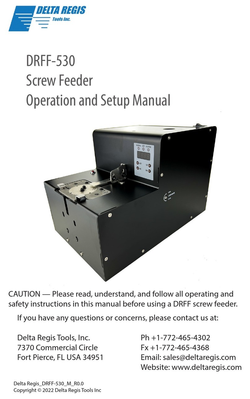
DRFF-530R
Screw Feeder
Operation and Setup Manual
CAUTION — Please read, understand, and follow all operating and
safety instructions in this manual before using a DRFF screw feeder.
If you have any questions or concerns, please contact us at:
Delta Regis Tools, Inc. Ph +1-772-465-4302
7370 Commercial Circle Fx +1-772-465-4368
Fort Pierce, FL USA 34951 Email: sales@deltaregis.com
Website: www.deltaregis.com
Delta Regis_DRFF-530R_M_R0.0
Copyright © 2022 Delta Regis Tools Inc

DRFF-530R Screw Feeder
Operation and Setup Manual
www.deltaregis.com 2
Warning — Failure to understand and follow proper installation guidelines, safety requirements,
and operating instructions may result in malfunction, component damage, property damage,
shock hazard, re hazard, injury or death.
• Please read and understand the operation manual and follow all safety and operation
instructions.
• Use these products in a suitable dry, indoor location. Do not use the screw feeder in damp,
wet, or high temperature environments. Do not use in the presence of ammable liquids or
gases.
• Use only a properly grounded electrical outlet of the correct supply voltage to power the
screw feeder.
• Ensure that the supply outlet is overload protected and of sucient amperage capacity.
• Use only the supplied AC adapter and power cord for the screw feeder and outlet. Hold the
plug of the power cord when connecting or disconnecting. Do not pull on the cable.
• Do not expose the cable, AC adapter or screw feeder to oil, chemicals, or heat. Ensure that
the cable is routed and used in such a manner as to not be subject to sharp objects that
may abrade or cut the cable.
• Locate the screw feeder in a suitable, safe location on a steady, level surface.
• Do not place in a high location where there may be a risk of it falling.
• Do not tilt the screw feeder.
• Do not raise the front or rear of the screw feeder.
• The screw feeder rail must be kept free from oil, grease, dust or any other contaminates.
• Do not place you hand or any foreign objects into the screw hopper when the unit is
running.
• In the event that the screw feeder is overloaded beyond the maximum current rating, an
internal circuit will disrupt power and the screw feeder will produce an error code. Should
the screw feeder stop functioning, or exhibit abnormal or intermittent operation, please
discontinue use immediately and send the screw feeder to an authorized service center for
troubleshooting and repair.
• Turn the main power switch o when the screw feeder is not being used. Unplug the screw
feeder if it is not being used on a regular basis.
• Do not attempt to disassemble or repair the screw feeder. Repairs should only be
performed by qualied technicians properly trained in the safe operation, troubleshooting,
and repair of these devices. Please consult Delta Regis for the location of the nearest service
depot.
• Use only the factory specied Delta Regis brand replacement parts and accessories with
these screw feeders.
• Any damage to the screw feeder resulting from misuse, abuse, or failure to follow these
guidelines will void the limited product warranty.
Grounding — The AC power cord is equipped with a 3-prong electrical receptacle/plug with
ground pin. The screw feeder must be connected to a properly grounded AC electrical outlet. Do
not attempt to use this screw feeder without a properly functioning ground connection. Never
connect a live circuit to the ground pin or internal yellow-green ground wire.

DRFF-530R Screw Feeder
Operation and Setup Manual
www.deltaregis.com 3
Included Accessories
This machine has been set up according to the sample fasteners and/
ortechnicaldrawingyouhad providedusduringyourpurchase.If ne
tuning is required, please follow the instructions starting on page 5.
2.5mm hex key
AC Adapter with power cord
Grounding wire
(ESD applications)
Flat head screwdriver

DRFF-530R Screw Feeder
Operation and Setup Manual
www.deltaregis.com 4
Product Overview
1 - Rail Gates
2 - Power Switch
3 - Screw Present/Error LED
4 - Programming Key Pad w/ LCD
5 - DC Receptacle
6 - Grounding Lug
(ESD Applications)
7 - I/O Signal
1
1
2
3
4
567

DRFF-530R Screw Feeder
Operation and Setup Manual
www.deltaregis.com 5
User Adjustments
Screw Guide Plate
1. Locate and loosen highlighted screws using a 2mm hex key.
2. Using the included shims, insert under the screw head guide,
press down on the plate and tighten screws from step 1.
Remove shims.

DRFF-530R Screw Feeder
Operation and Setup Manual
www.deltaregis.com 6
User Adjustments
Screw Guide Plate (Continued)
3. Add several screws into the rail assembly. Tilt the screw
feeder forward, ensure the screws can smoothly pass under
the guide plate.
NOTE:
When adjusting the screw guide plate, the screws from step 1
must be fully tightened to avoid loosening during use.
Infrared Sensor Adjustment
1. Loosen the highlighted screws using a 2mm hex key.

DRFF-530R Screw Feeder
Operation and Setup Manual
www.deltaregis.com 7
Infrared Sensor Adjustment (Continued)
2. Adjust the infrared openings so only half of the opening is
exposed, tighten screws from step 1.
NOTE:
Only half of the infrared opening can be exposed. If
the screw cannot be detected, you can make further
adjustments.

DRFF-530R Screw Feeder
Operation and Setup Manual
www.deltaregis.com 8
User Adjustments
Brush Adjustment
1. Loosen the highlighted screws using a 2.5mm hex key.

DRFF-530R Screw Feeder
Operation and Setup Manual
www.deltaregis.com 9
User Adjustments
Brush Adjustment (Continued)
2. Insert several screws into the rail, under the brush.
Manually sweep the brush across the screw heads. Adjust
the brush so slightly touches the screw heads. Re-tighten
the screws from step 1.
NOTE:
The brush holder must not make contact with any surface of
the hopper. Ensure a gap exists to avoid jamming.
The brush bristles are tapered.

DRFF-530R Screw Feeder
Operation and Setup Manual
www.deltaregis.com 10
Filling the Hopper
Before lling the hopper, turn the machine OFF.
Remove the hopper cover. Check for debris or foreign objects.
Fill the hopper with screws leaving a minimum of 2 mm space
under the rail for thread lengths up to 5mm, 4mm space for
thread lengths over 5mm.
The hopper capacity is approximately 500cc (30.51ci).
Mixed screws, debris and/or foreign objects must be removed
to prevent poor performance.
2mm
2mm
4mm
4mm

DRFF-530R Screw Feeder
Operation and Setup Manual
www.deltaregis.com 11
Removing Screws
Using a magnetized bit, hold your electric screwdriver at a
vertical orientation, move the screwdriver’s bit to the bit guide,
slide down the guide to the screw head, momentarily start
the screwdriver to engage the bit with the screw and pull the
screwdriver away from the feeder.
NOTE:
Do not use excessive downward force to avoid damage to the
machine.
Do not apply excessive force to the bit guide to avoid damage
to the machine.

DRFF-530R Screw Feeder
Operation and Setup Manual
www.deltaregis.com 12
Programming
LCD Display & Programming Keys
1. In any state, long press the SET button for 3 seconds, the system enters
programing mode, the SET light illuminates, and the program selection is
activated. Currently, the rst two digits of the display are ashing, and the last
two digits are steady to display the program value under this program. Short
press the UP or DN key to select the program to be adjusted.
2. After selecting the program to be adjusted, short press the OK key to enter
the value under this program. Currently, the rst two digits of the display are
solid, and the last two digits are ashing. Short press the UP or DN key to set
the program value.
3. After the program value has been set, short press the OK key to exit the
setting under this item and return to the program selection.
4. When nishing programming, wait 3 seconds to auto-exit programming
mode.
5. To reset the total screw count: long press the SET key and OK key at the same
time, the total count will be reset to zero.
6. Normal Mode and Counter Mode can be switched by pressing “OK”. Program
01 must have a value of 01 or greater to enable switching between these
modes. A value of 00 will only allow Normal Mode to function.

DRFF-530R Screw Feeder
Operation and Setup Manual
www.deltaregis.com 13
NOTE:
Normal Mode = Accumulative Count
Counter Mode = Batch Count
Program Program Name Program Description (set by using UP/DN)
01 Fastener Count
Set the target number of fasteners to count
(Program Value: 00-99 (00 disables Counter
Mode))
02 Counting Method
Set the counting method of Program 01 - Must
have a value set for Program 01 & Counter Mode
enabled
(Program Value: 00: increase; 01: decrease)
03 Buzzer Turn the buzzer on or o
(Program value: 00: OFF; 01 ON)
04 Vibration Motor
Shutdown Delay
Set the delay time for the vibration motor to stop
when screw present
(Program Value: 01-20 (1 second per unit))
05 Vibration Motor
Speed
Set the operating speed of the vibration motor
(Program Value: 01-20 (01 min, 20 max))
06 Drum Motor
Shutdown Delay
Set the delay time for the drum motor to stop
when screw present
(Program Value: 01-20 (1 second per unit))
07 Drum Motor
Speed
Set the operating speed of the drum motor
(Program Value: 01-10 (01 min, 10 max))
08 Turntable Motor
Speed
Set the operating speed of the turntable motor
(Program Value: 01-10 (01 min, 10 max))
09 Vibration Motor
Rotation
Set the direction of the vibration motor
(Program Value: 00: CW Rotation; 01: CCW
Rotation)
10 Drum Motor Pause
Set the number of counted fasteners to start the
drum motor
(Program Value: 00-20 (00 disable))
11 Turntable Motor
Start Delay
Set the delay time for the turntable motor to start
(Program Value: 01-10 (0.5 seconds per unit))

DRFF-530R Screw Feeder
Operation and Setup Manual
www.deltaregis.com 14
12 Infrared Sensor
Voltage
Enters diagnostic mode and displays the DC
voltage of the infrared sensors ~0470 when open,
~5000 when screw present
(Program Value: 00: disable; 01 enable)
13 Screw Specication Set according to the thickness of the screw head
(Program Value: 00: Large Screw; 01: Small Screw)
14 Brush Motor
Shutdown Delay
Set the delay time for the brush motor to stop
when screw present
(Program Value: 01-20 (1 second per unit))
15 Brush Motor Speed Set the operating speed of the brush motor
(Program Value: 01-10 (01 min, 10 max))
NOTE:
1. Vibration motor shutdown delay value must never exceed brush motor shutdown
delay value in order to prevent screws from jamming at the screw head guide plate.
2. When Program 12 is enabled, the vibration and drum & brush motors will not run.
The turntable will rotate at minimum speed for several cycles before stopping. Once
the turntable has stopped, adjust the infrared sensors to display ~2500 for optimal
sensing. After the adjustment has been made, turn the machine o then on to
continue using the machine. Screws with a small headed may require a value greater
than 2500.
3. Program 13 is set based on the thickness of the screw head. If the screw head is
0.5mm or less, use 01. If the screw head is greater than 0.5mm, use 00.
Error Codes
Error Code Description
E-01 Drum/Brush motor seized
E-02 Turntable motor seized
E-03 Drum/Brush motor not detected
E-04 Vibration motor not detected
E-05 Drum/Brush and Vibration motor not communicating

DRFF-530R Screw Feeder
Operation and Setup Manual
www.deltaregis.com 15
Troubleshooting
Problem Reason Solution
Turn on power,
no function or
abnormal sound
The power supply is
not plugged in or the
connection is loose
Check the AC adapter and
power cord for proper
termination
Excessive amount of
screws in the hopper
Remove excess amount of
screws (see page 10)
Power switch, motor or
PCB failure
Replace switch, motor or
PCB
Screws falling into
machine
Ensure the top and side
gates are properly closed
and remove all screws from
inside the machine
Infrared sensors
misaligned
Adjust the alignment of the
sensors (see page 7 &14)
Infrared sensors blocked
Clear obstruction and/
or clean sensors with
compressed air
The drum does not
rotate
Drum/brush motor
failure
Replace the drum/brush
motor
Foreign material or
debris stuck in drum
gears
Remove the foreign
material or debris
Screws do not slide
down the rail
Rail gap to narrow Adjust the rail gap
Screw has become
lodged at the screw
head guide plate and
cannot be swept by the
brush
Remove lodged screw and
adjust brush
In the event of a fault, immediately disconnect the power supply and perform
the following troubleshooting.

DRFF-530R Screw Feeder
Operation and Setup Manual
www.deltaregis.com 16
Problem Reason Solution
Gate opening(s) too
tight
Adjust the gates (0.2mm
gap)
Height of screw head
guide plate too low
Adjust the height of the
guide plate (see page 5)
Vibration motor speed
no good at current
setting
Adjust Program 05 until
screws feed smoothly
No signal output (if
equipped)
Relay PCB damaged or
wire disconnected
1. Use a voltmeter set to
ohms. Circuit is open when
no screw present, circuit is
closed when screw present
2. Reconnect wire to PLC
and/or relay PCB
Main PCB damaged
or relay wire harness
disconnected
1. Reconnect wire harness
to main PCB
2. Return for service
Buzzer on,
indication LED
steady on
Main PCB damaged Return for service
NOTE:
If any of the above error codes appear on the LCD, please turn o
the unit immediately, unplug the power source and return the unit
for service.
Continued use in a fault state will void your warranty.

DRFF-530R Screw Feeder
Operation and Setup Manual
www.deltaregis.com 17
Maintenance
Before maintaining the machine, turn o power and disconnect the power.
Brush cleaning & maintenance:
Wipe the front end of the bristles with a dry, lint free cloth or compressed air to
remove dirt and debris. Sweep the brush manually to ensure it makes contact
with the screw heads, adjust brush as needed. Brushes worn to the point they
cannot make contact with the screw heads, replace immediately.
Rail cleaning & maintenance:
Using a lint free swab dipped in alcohol, clean the inner rail surfaces, clean the
rail’s sliding surface very well as to remove any debris or oil.
Cleaning and maintaining the machine:
Remove the side covers and check for foreign screws and/or debris that
may have fallen inside the machine. Use compressed air to remove any
accumulated dust. Check all accessible fasteners to ensure they are tight
before reinstalling the covers.
Parts and Accessories
If you require parts or accessories for your Delta Regis product, please refer to
our website or contact us for further information. Use only genuine Delta Regis
parts when servicing these products.

DRFF-530R Screw Feeder
Operation and Setup Manual
www.deltaregis.com 18
Service
The DRFF Series screw feeders are not user serviceable. Any repairs must be
performed by a Delta Regis authorized service center. Please consult Delta
Regis Tools for further information and the location of the nearest authorized
service center. Repairs to the DRFF Series screw feeders must be performed
by trained personnel, knowledgeable and qualied in the repair of said
machinery.
Do not attempt to modify this machine.
Warranty
The DRFF Series screw feeders are warranted for one year from the date of
purchase against defects in material and workmanship. This warranty does
not cover damage due to transportation, abuse, misuse, modication or
improper service. Our sole remedy is to repair or replace (at our discretion)
any unit found to be defective due to defects in material or workmanship. It
is the responsibility of the user to return any product thought to be defective,
freight prepaid, to our warehouse for inspection and evaluation. There is no
warranty of merchantability or tness of purpose. In no event will Delta Regis
Tools, Inc. be liable for business interruptions, loss of prots, harm, injury,
damage, personal injury, cost of delay, or any other special, indirect, incidental,
or consequential losses, costs, or damages.
If you have questions or require assistance with this machine, please
contact us by phone at 772-465-4302 or email sales@deltaregis.com

DRFF-530R Screw Feeder
Operation and Setup Manual
www.deltaregis.com 19
Declara�on of Conformity
Delta Regis Tools Inc.
7370 Commercial Circle
Fort Pierce, FL USA
34951
Ph (772)465-4302
Product: Screw Feeder
Trade Name: Delta Regis
Applicable Models: DRFF-530R, DRFF-530, DRFF-630C
The undersigned hereby declares, on behalf of Delta Regis Tools, Inc., that the product designated in
this declara�on is in conformity with the provisions of:
MD Direc�ve 2006/42/EC
Standards EN 62841-1:2018
EN ISO 12100:2010
EN ISO 13849-1:2015
Issue Date: Dec 22, 2021
_________________________
Aaron Smeal
Opera�ons Manager
DELTA REGIS_DRFF-520_DRFF-630C_CE_R0.0
Table of contents
Other Delta Regis Wire Feeder manuals
Popular Wire Feeder manuals by other brands

FONRI
FONRI BL4 user guide

Siemens
Siemens SIRIUS S00 Original operating instructions

Lincoln Electric
Lincoln Electric FLEX FEED 74 HT Operator's manual

Textron
Textron Greenlee 6810 instruction manual

Castolin Eutectic
Castolin Eutectic ArcWeld 484 P instruction manual

Axiom
Axiom MF Series Installation operation & maintenance