Capacitor Discharge 3300828-F User manual

I MANUALE DI ISTRUZIONI PER SALDATRICE A
SCARICA DI CONDENSATORI pag. 2
GB INSTRUCTION MANUAL FOR CAPACITOR DISCHARGE
WELDING MACHINE page 7
D BETRIEBSANLEITUNG FÜR KONDENSATOR-STOSSENTLADUNG-
SSCHWEISSMASCHINE Seite 12
F MANUEL D'INSTRUCTIONS POUR POSTE A SOUDER
A DECHARGE DE CONDENSATEURS page 17
E MANUAL DE INSTRUCCIONES PARA SOLDADORA
DE DESCARGA DE CONDENSADORES pag. 22
20/03/13
3.300.828/F
Pagg. Seiten: 27-31
Parti di ricambio e schema elettrico
Spare parts and electrical schematic
Ersatzteile und Schaltplan
Pièces détachées et schéma électrique
Partes de repuesto y esquema eléctrico

2
IMPORTANTE: PRIMA DELLA MESSA IN OPERA DEL-
L'APPARECCHIO LEGGERE IL CONTENUTO DI QUESTO
MANUALE E CONSERVARLO, PER TUTTA LA VITA OPE-
RATIVA, IN UN LUOGO NOTO AGLI INTERESSATI.
QUESTO APPARECCHIO DEVE ESSERE UTILIZZATO
ESCLUSIVAMENTE PER OPERAZIONI DI SALDATURA.
1 PRECAUZIONI DI SICUREZZA
LA SALDATURA ED IL TAGLIO AD ARCO POSSONO
ESSERE NOCIVI PER VOI E PER GLI ALTRI, pertanto l'uti-
lizzatore deve essere istruito contro i rischi, di seguito rias-
sunti, derivanti dalle operazioni di saldatura. Per informazio-
ni più dettagliate richiedere il manuale cod.3.300758
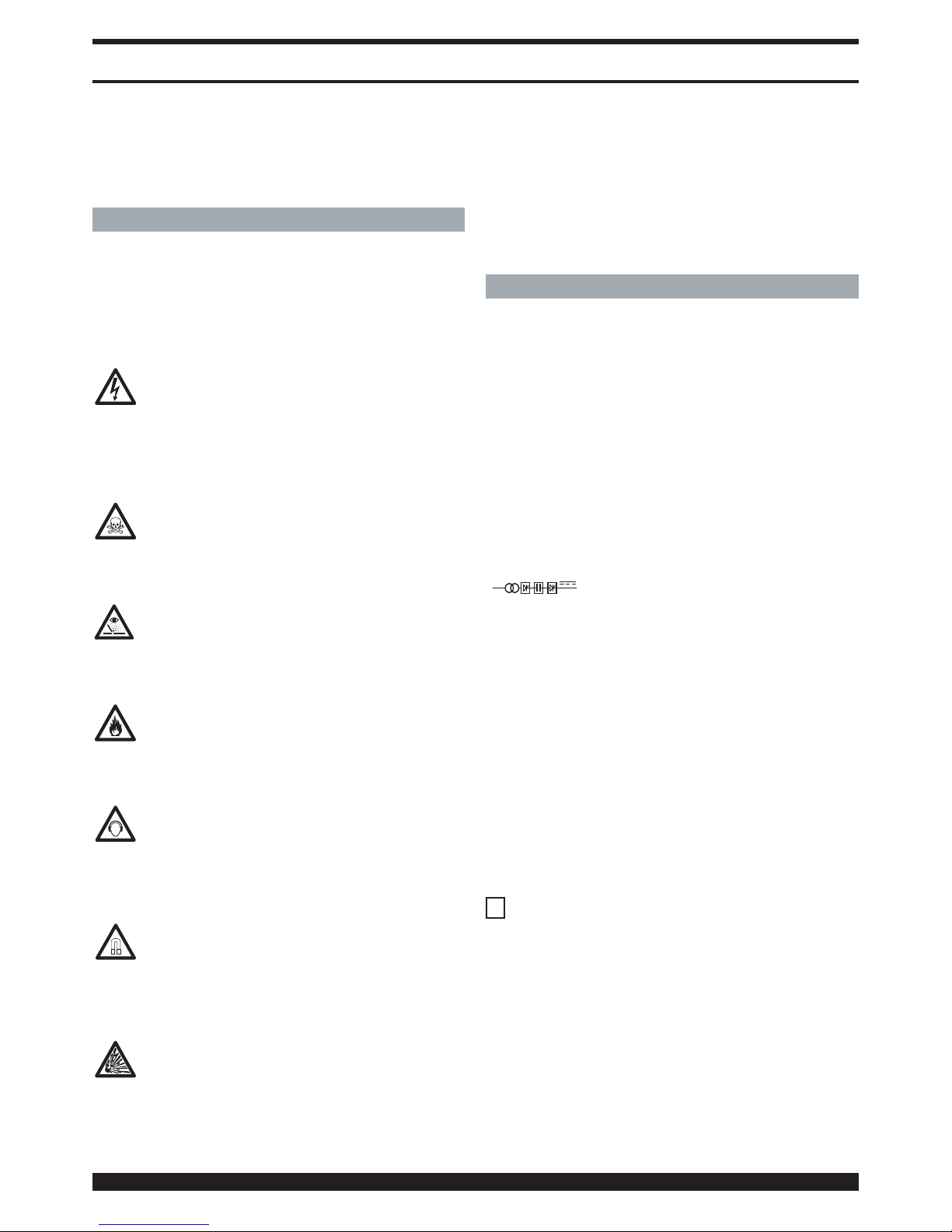
SCOSSA ELETTRICA - Può uccidere.
· Installate e collegate a terra la saldatrice secondo
le norme applicabili.
· Non toccare le parti elettriche sotto tensione o gli
elettrodi con la pelle nuda, i guanti o gli indumenti bagnati.
· Isolatevi dalla terra e dal pezzo da saldare.
· Assicuratevi che la vostra posizione di lavoro sia sicura.
FUMI E GAS - Possono danneggiare la salute.
· Tenete la testa fuori dai fumi.
· Operate in presenza di adeguata ventilazione ed
utilizzate aspiratori nella zona dell’arco onde evitare
la presenza di gas nella zona di lavoro.
RAGGI DELL’ARCO - Possono ferire gli occhi e bruciare la pelle.
· Proteggete gli occhi con maschere di saldatura
dotate di lenti filtranti ed il corpo con indumenti
appropriati.
· Proteggete gli altri con adeguati schermi o tendine.
RISCHIO DI INCENDIO E BRUCIATURE
· Le scintille (spruzzi) possono causare incendi e
bruciare la pelle; assicurarsi, pertanto che non vi
siano materiali infiammabili nei paraggi ed utilizzare
idonei indumenti di protezione.
RUMORE
Questo apparecchio non produce di per se rumori
eccedenti gli 80dB. Il procedimento di taglio pla-
sma/saldatura può produrre livelli di rumore supe-
riori a tale limite; pertanto, gli utilizzatori dovranno mettere in
atto le precauzioni previste dalla legge.
PACE MAKER
· I campi magnetici derivanti da correnti elevate pos-
sono incidere sul funzionamento di pacemaker. I por-
tatori di apparecchiature elettroniche vitali (pace-
maker) dovrebbero consultare il medico prima di avvicinar-
si alle operazioni di saldatura ad arco, di taglio, scriccatura o
di saldatura a punti.
ESPLOSIONI
· Non saldare in prossimità di recipienti a pressione
o in presenza di polveri, gas o vapori esplosivi. ·
Maneggiare con cura le bombole ed i regolatori di
pressione utilizzati nelle operazioni di saldatura.
COMPATIBILITÀ ELETTROMAGNETICA
Questo apparecchio è costruito in conformità alle indicazio-
ni contenute nella norma armonizzata EN50199 e deve
essere usato solo a scopo professionale in un ambiente
industriale. Vi possono essere, infatti, potenziali diffi-
coltà nell'assicurare la compatibilità elettromagnetica in
un ambiente diverso da quello industriale.
IN CASO DI CATTIVO FUNZIONAMENTO RICHIEDETE
L’ASSISTENZA DI PERSONALE QUALIFICATO.
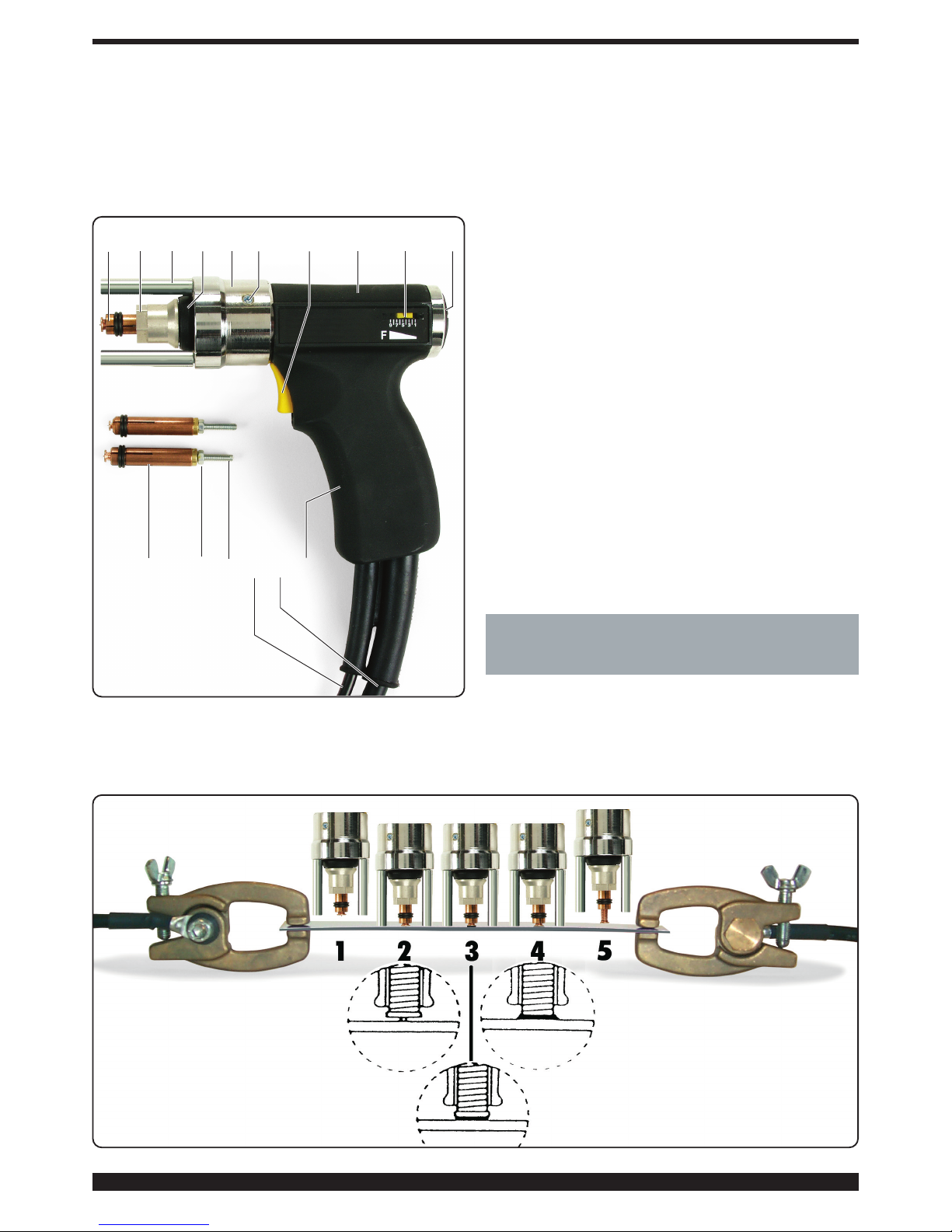
2 DESCRIZIONI GENERALI
2.1 SPECIFICHE
La macchina è stata progettata e realizzata per la saldatura
di prigionieri filettati Ø 4, 5 e 6 mm, ferrosi e non ferrosi.
Questo sistema di saldatura utilizza la scarica estremamen-
te rapida (2-3 ms) di una batteria di condensatori che con-
sente la saldatura di prigionieri filettati con innesco a punta
di accensione.
2.2 SPIEGAZIONE DEI DATI TECNICI RIPORTATI
SULLA TARGA DI MACCHINA
N° Numero di matricola da citare sempre per qual-
siasi richiesta relativa alla saldatrice.
IEC 60974-1 La saldatrice è costruita secondo queste
EN 50199 norme internazionali.
Trasformatore monofase-raddrizzatore con
dispositivo per la carica e la scarica di
condensatori.
U0 Tensione a vuoto secondaria.
E Energia di saldatura.
C Valore della capacità.
Uc Tensione regolabile sui condensatori.
U1 Tensione nominale di alimentazione.
La macchina è prevista per le tensioni 115V e
230V con cambio tensione automatico.
1-50/60Hz Alimentazione monofase 50 oppure 60Hz.
I1max Corrente massima assorbita alla corrisponden-
te tensione di alimentazione.
IP23C Grado di protezione della carcassa. Grado 3
come seconda cifra significa che l'apparecchio
è idoneo a lavorare all'esterno sotto la pioggia.
C: la lettera addizionale C significa che l'appa-
recchio è protetto contro l'accesso di un utensi-
le (diametro 2,5 mm) alle parti in tensione del
circuito di alimentazione.
SIdonea a lavorare in ambienti con rischio accre-
sciuto
NOTE: Idonea a lavorare in ambienti con grado di inquina-
mento 3 (vedi IEC 60664-1)
2.3 DESCRIZIONE DELLE PROTEZIONI
2.3.1 Protezione termica
Questo apparecchio è protetto da un termostato il quale, se
si superano le temperature ammesse, impedisce il funzio-
namento della macchina. In queste condizioni il ventilatore
continua a funzionare ed il display indicherà il codice di erro-
re E1.
1~
MANUALE DI ISTRUZIONI PER SALDATRICE A SCARICA DI CONDENSATORI

3 INSTALLAZIONE
L'installazione della macchina deve essere fatta da perso-
nale esperto. Tutti i collegamenti debbono essere eseguiti in
conformità alle norme vigenti e nel pieno rispetto della legge
antinfortunistica (norma CEI 26-10- CENELEC HD 427).
1 Collocare la saldatrice in una posizione stabile e sicura.
La circolazione dell'aria deve essere libera in entrata e in
uscita e la saldatrice deve essere protetta dall'ingresso di
liquidi, sporco, limature metalliche ecc.
2 Controllare che la tensione di alimentazione corrisponda
alla tensione indicata sulla targa dei dati tecnici della sal-
datrice.
Collegare una spina di portata adeguata al cavo di ali-
mentazione assicurandosi che il conduttore giallo/verde
sia collegato allo spinotto di terra.
La portata dell'interruttore magnetotermico o dei fusibili,
in serie alla alimentazione, deve essere uguale alla cor-
rente I1 assorbita dalla macchina.
Eventuali prolunghe debbono essere di sezione adegua-
ta alla corrente I1 assorbita.
Se l' alimentazione è 115V, la macchina può funzionare
per tensioni comprese tra 96V e 140V.
Se l' alimentazione è 230V, la macchina può funzionare
per tensioni comprese tra 190V e 260V.
Il cambio di alimentazione deve essere eseguito a mac-
china spenta.
3
3 Ai portatori di pace maker è proibito usare la macchina o
avvicinarsi ai cavi.
4 Inserire a fondo la spina del cavo di massa nella presa +
e ruotare in senso orario.
5 Inserire a fondo la spina della pistola nella presa -e ruo-
tare in senso orario.
6 Accendere la saldatrice con l'interruttore I. (l'accensione
e lo spegnimento non vanno ripetuti con frequenza
perché la dissipazione dell'energia contenuta nei con-
densatori può causare riscaldamento e danni).
7 Per limitare l'esposizione al campo magnetico tenere il
cavo della pistola dal lato della mano che la impugna, evi-
tando di avvolgersi con il cavo.
3.1 DESCRIZIONE DELL'APPARECCHIO
A-Tasto per aumentare la tensione di carica dei conden-
satori
B-Tasto per diminuire la tensione di carica dei conden-
satori
C-Led che indica la macchina accesa
D-Led che si accende durante la fase di saldatura
E-Display che indica la tensione di carica dei condensa-
tori
F- Morsetto di uscita positivo
G-Morsetto di uscita negativo
A
B
FG
H
C
D
E
J
I
Fig. 1

4
H-Connettore per il pulsante della torcia
I- Interruttore generale
J- Fusibile Ø 6,3x32 (tipo ritardato). L'apparecchio è
provvisto di un fusibile da 16A per alimentazione 115V,
per alimentazione 230V può essere utilizzato un fusibi-
le da 10A.
3.2 DESCRIZIONE PISTOLA
K-Corpo pistola
L- Impugnatura
M-Cavetto di comando
N-Cavo corrente di saldatura
O-Pulsante comando di saldatura (agisce solo con la
pistola premuta sulla lamiera)
P-Indice regolazione forza
Q-Vite per la regolazione della forza (aumenta ruotando
in senso orario)
R-Anello porta distanziale Z
S-Ghiera di bloccaggio pinza
T- Soffietto di protezione
U-Viti di bloccaggio dell'anello R
V-Vite per la regolazione della sporgenza del prigioniero
W-Dado di bloccaggio.
X-Pinza di presa del prigioniero
Y-Vite
Z-Distanziale
3.2.1 Preparazione della pistola
Usare sempre perni con innesco a punta di accensione per
saldatura a scarica di condensatori di qualità elevata, rispon-
denti alle norme e di metallo compatibile con le saldature da
eseguire.
Scelto il prigioniero da saldare per tipo, diametro, lunghezza
e materiale, utilizzare e regolare la pinza in base al diametro
corrispondente.
Inserire il prigioniero nella pinza Xin modo che sia ben ser-
rato dalle quattro molle.
Regolare la sporgenza del prigioniero rispetto alla parte
anteriore della pinza a 0,8 ÷ 1,2 mm utilizzando la vite V quin-
di bloccare con il dado W (figura 2).
Inserire la pinza Xnel mandrino della pistola (fig. 2), premer-
la fino a sentirla appoggiare in fondo e bloccare il dado S con
la chiave esagono 17 mm in dotazione.
4 PRINCIPIO DI FUNZIONAMENTO DELLA SALDATU-
RA DI PRIGIONIERI FILETTATI CON INNESCO A
PUNTA DI ACCENSIONE (Fig. 3)
Il prigioniero viene inserito nella pinza X(fase 1), quindi viene
posizionato e premuto con il suo innesco di accensione
direttamente sulla superficie della lamiera da saldare (fase 2.
La molla della pistola preme il prigioniero contro il metallo, il
comando di start fa iniziare il passaggio di corrente che
vaporizza l'innesco di accensione e l'arco elettrico si propa-
X
XWVMNL
SZTRU O K P Q
Fig. 2
Fig. 3

5
ga su tutta la superficie del prigioniero (fase 3) che viene
spinto sulla superficie metallica. Il metallo fuso solidifica sal-
dando il prigioniero (fase 4).
L'estrazione della pistola deve avvenire perfettamente alli-
neata con il perno per non deformare la pinza e assicurarne
così una lunga vita (fase 5).
5 SALDABILITA' DI COMBINAZIONI TIPICHE FRA
PRIGIONIERO E METALLO BASE PER SALDATURA
CON SCARICA DI CONDENSATORI. (Tabella 1)
E' importante studiare con particolare attenzione la resisten-
za e la deformazione nel punto di saldatura fra prigioniero e
metallo base. Nel caso dell'acciaio, si deve prestare partico-
lare attenzione alla fragilità da indurimento.
Il materiale e la resistenza del prigioniero sono soggetti a tol-
leranza ristretta. il contenuto di carbonio nei prigionieri filet-
tati in acciaio deve essere < 0,20%.Metallo prigionieri
La superficie del metallo base deve essere pulita. Strati di
vernice, ruggine, scorie, grasso e rivestimenti di metalli non
saldabili, devono essere rimossi dalla zona di saldatura.
Questo si deve fare con mezzi idonei. I metalli di base con
strati di scorie e ruggine devono essere perfettamente puliti.
6 SALDATURA
Questa tecnologia permette di saldare prigionieri filettati su
superfici pulite, ma non ossidate, di acciaio dolce, acciaio
galvanizzato, acciaio inox, alluminio e ottone.
La rapidità del processo non altera le superfici sul lato oppo-
sto alla saldatura. La saldatura non è possibile su acciaio
temperato, metallo ossidato o verniciato.
Prima di iniziare la produzione è indispensabile, effettuare
alcune saldature di prova per determinare la corretta regola-
zione del generatore e la taratura della pistola (forza della
molla) operando come segue:
· inserire il prigioniero scelto nella pinza X (preventivamente
regolata come descritto in Fig. 2)
· disporre la lamiera di base in condizioni identiche a quelle
che saranno le condizioni di lavoro come spessore, area dei
Acciaio 0,2 C Inox Ottone Al. Mg 3 AISi 12 Al. 99,5
ramato Cu Zn 38
Acciaio fino a 0,30 C % A A A - - A
Acciaio zincato B B A - - -
Acciaio inossidabile A A B - - -
Ottone A B A - - -
Rame B - A - - -
Al 99,5 - - - A B B
Al Mg 1 - - - B A B
Al Mg 3 - Al Mg 5 - - - B A B
Al Mg Si - - - B A B
Buona saldabilità: A Bassa saldabilità: B Non saldabili: -
Tab.1
collegamenti di massa, dimensioni del pezzo, qualità del
materiale.
· i morsetti del cavo di massa vanno collocati in modo sim-
metrico ed il più vicino possibile al punto di saldatura.
· attivare il generatore tramite l'interruttore luminoso I.
· impugnare la pistola e premerla sulla lamiera verificando
che l'asse risulti perpendicolare al piano. Se la superficie del
materiale su cui saldare il prigioniero è piana, consigliamo di
montare i tre distanziali Z dopo avere svitato le viti Y.
· eseguire alcune saldature regolando la tensione con i tasti
A e B e la forza della pistola con la regolazione Q fino ad
ottenere saldature perfette.
La pistola va estratta tenendola perfettamente allineata al
perno per non deformare la pinza (Fig4).
6.1SALDATURA DELL'ALLUMINIO
Per saldare prigionieri filettati M4 in lega di alluminio Al Si 12
su lamiera di alluminio per carrozzeria regolare la tensione a
105/115V. La molla della pistola che regola la pressione
durante la saldatura andrà regolata in modo che l'indice P
sia su 2/2,5.
Fig. 4
Metallo base
Metallo prigionieri

6
7 MANUTENZIONE
7.1 ORDINARIA
Conservare leggibili e chiare le indicazioni e le figure sulla
saldatrice.
Il cavo rete ed i cavi di saldatura debbono essere isolati e in
perfette condizioni; fare attenzione ai punti dove subiscono
flessioni: vicino ai morsetti di collegamento, alle pinze di
massa e all'ingresso nella pistola.
Mantenere puliti e ben serrati i connettori della corrente di
saldatura alle prese F e G (vedi Fig. 1)
I morsetti per il collegamento con il metallo base debbono
fare un buon contatto per evitare riscaldamento, scintille, cir-
colazione non bilanciata della corrente, danni al componen-
te dove vanno saldati i perni e saldature di qualità non
costante. Impedire l'ingresso di sporco, polvere e limatura
all'interno della saldatrice.
Garantire sempre la circolazione dell'aria di raffreddamento.
Controllare che il ventilatore funzioni regolarmente.
Verificare che le pinze serrino bene i prigionieri con tutte le
molle di contatto.
Il mandrino portapinze deve scorrere libero per tutta la sua
corsa, senza variazioni dovute ad attriti o corpi estranei.
7.2 STRAORDINARIA
La manutenzione deve essere eseguita da personale qualifi-
cato
Alcune anomalie di funzionamento sono evidenziate dall'ac-
censione di un codice di errore su display E.
Codice Anomalia Rimedio
errore
E 1 Intervento del Attendere alcuni
termostato minuti
E 2 SCR in corto Contattare
circuito l'assistenza
E 2 Connettore non Inserire il
inserito correttamente connettore
E 3 Tensione irregolare Contattare
ai capi dei condensatori l'assistenza
E 4 Carica dei Contattare
condensatori irregolare l'assistenza
E 5 Scarica dei Contattare
condensatori irregolare l'assistenza
Prima di aprire la saldatrice attendere almeno 5 minuti dallo
spegnimento dell'interruttore I inoltre scollegare la spina
dalla presa di alimentazione.
Controllare con un voltmetro che i condensatori siano scari-
chi.
Togliere polvere, frammenti e limature metallica dalla mac-
china con cura usando aria compressa per non danneggia-
re o proiettare frammenti metallici sulle parti elettroniche o
elettriche.
Verificare che tutti i connettori siano inseriti a fondo.
Verificare che tutti i terminali del circuito di saldatura siano
ben serrati.
Dopo aver eseguito una riparazione, fare attenzione a riordi-
nare il cablaggio in modo che vi sia un sicuro isolamento tra
il lato primario ed il lato secondario della macchina. Evitare
che i fili possano andare a contatto con parti in movimento
o parti che si riscaldano durante il funzionamento. Rimontare
tutte le fascette come sull'apparecchio originale in modo da
evitare che, se accidentalmente un conduttore si rompe o si
scollega, possa avvenire un collegamento tra il primario ed il
secondario.
Rimontare inoltre le viti con le rondelle dentellate come sul-
l'apparecchio originale.

7
IMPORTANT: BEFORE STARTING THE EQUIPMENT,
READ THE CONTENTS OF THIS MANUAL, WHICH MUST
BE STORED IN A PLACE FAMILIAR TO ALL USERS FOR
THE ENTIRE OPERATIVE LIFE-SPAN OF THE MACHINE.
THIS EQUIPMENT MUST BE USED SOLELY FOR WELD-
ING OPERATIONS.
1 SAFETY PRECAUTIONS
WELDING AND ARC CUTTING CAN BE HARMFUL TO
YOURSELF AND OTHERS. The user must therefore be edu-
cated against the hazards, summarized below, deriving from
welding operations. For more detailed information, order the
manual code 3.300.758
ELECTRIC SHOCK - May be fatal.
· Install and earth the welding machine according to
the applicable regulations.
· Do not touch live electrical parts or electrodes with
bare skin, gloves or wet clothing.
· Isolate yourselves from both the earth and the workpiece.
· Make sure your working position is safe.
FUMES AND GASES - May be hazardous to your health.
· Keep your head away from fumes.
· Work in the presence of adequate ventilation, and
use ventilators around the arc to prevent gases from
forming in the work area.
ARC RAYS - May injure the eyes and burn the skin.
· Protect your eyes with welding masks fitted with fil-
tered lenses, and protect your body with appropriate
safety garments.
· Protect others by installing adequate shields or curtains.
RISK OF FIRE AND BURNS
· Sparks (sprays) may cause fires and burn the skin;
you should therefore make sure there are no flam-
mable materials in the area, and wear appropriate
protective garments.
NOISE
This machine does not directly produce noise
exceeding 80dB. The plasma cutting/welding proce-
dure may produce noise levels beyond said limit;
users must therefore implement all precautions required by
law.
PACEMAKERS
· The magnetic fields created by high currents may
affect the operation of pacemakers. Wearers of vital
electronic equipment (pacemakers) should consult
their physician before beginning any arc welding, cutting,
gouging or spot welding operations.
EXPLOSIONS
· Do not weld in the vicinity of containers under pres-
sure, or in the presence of explosive dust, gases or
fumes. · All cylinders and pressure regulators used in
welding operations should be handled with care.
ELECTROMAGNETIC COMPATIBILITY
This machine is manufactured in compliance with the
instructions contained in the harmonized standard
EN50199, and must be used solely for professional pur-
poses in an industrial environment. There may be poten-
tial difficulties in ensuring electromagnetic compatibility
in non-industrial environments.
IN CASE OF MALFUNCTIONS, REQUEST ASSISTANCE
FROM QUALIFIED PERSONNEL.
2 GENERAL DESCRIPTIONS
2.1 SPECIFICATIONS
The machine has been designed and built for welding fer-
rous and non-ferrous threaded stud bolts, Ø 4. 5 and 6 mm.
This welding system uses the extremely rapid (2-3 ms) dis-
charge of a battery of capacitors, which allows the welding
of threaded stud bolts with contact point start-up.
2.2 EXPLANATION OF THE TECHNICAL SPECIFICA-
TIONS LISTED ON THE MACHINE PLATE
N° Serial number, which must be indicated on any
request regarding the welding machine
IEC 60974-1 The welding machine is manufactured according
EN 50199 to these international standards.
Single-phase transformer-rectifier with
device for charging and discharging the
capacitors
U0 Secondary open-circuit voltage
E Welding energy
C Capacity value
Uc Voltage adjustable on the capacitors
U1 Rated supply voltage. The machine is set up for
voltages of 115V and 230V with automatic
voltage change.
1-50/60Hz 50- or 60-Hz single-phase power supply
I1 Max Max. absorbed current at the corresponding
supply voltage.
IP23C Protection rating for the housing. Grade 3 as the
second digit means that the equipment is
suit able for use outdoors in the rain.
C: The additional letter C means that the
equipment is protected against access to the
live parts of the power circuit by a tool (diameter
2.5 mm ).
S Suitable for use in high-risk environments.
NOTES: Suitable for use in environments with a pollution
rating of 3 (see IEC 60664-1)
2.3 DESCRIPTION OF PROTECTIVE DEVICES
2.3.1 Thermal protection
This machine is protected by a thermostat, which prevents
the machine from operating if the allowable temperatures are
exceeded. Under these conditions the fan keeps running
and the display will show error code E1.
1~
INSTRUCTION MANUAL FOR CAPACITOR DISCHARGE WELDING MACHINE

8
3 INSTALLATION
Only skilled personnel should install the machine. All con-
nections must be carried out according to current regula-
tions, and in full observance of safety laws (regulation CEI
26-10 - CENELEC HD 427).
1. Place the welding machine in a stable and safe position.
Air must circulate freely, both incoming and outgoing,
and the welding machine must be protected from entry
by liquids, dirt, metal filings, etc.
2. Make sure that the supply voltage matches the voltage
indicated on the specifications plate of the welding
machine. When mounting a plug, make sure it has an
adequate capacity, and that the yellow/green conductor
of the power supply cable is connected to the earth pin.
The capacity of the overload cutout switch or fuses
installed in series with the power supply must be equiv-
alent to the absorbed current I1 of the machine.
Any extension cords must be sized appropriately for the
absorbed current I1.
If the power supply is 115V, the machine may run for
voltages between 96V and 140V.
If the power supply is 230V, the machine may run for
voltages between 190V and 260V.
The machine must be switched off when changing the
power supply.
3. Pacemaker wearers are prohibited from using the
machine or approach the cables.
4. Fully insert the earth cable plug into the + socket and
turn clockwise.
5. Fully insert the gun plug into the - socket and turn clock-
wise.
6. Turn on the welding machine using the I switch. (start-up
and shutdown should not be repeated frequently,
because dissipating the energy contained in the capac-
itors may cause overheating and damage).
7. To limit exposure to the magnetic field, keep the gun
cable on the side of the hand holding it, avoiding wrap-
ping the cable around.
3.1 DESCRIPTION OF THE EQUIPMENT
A- Key to increase the capacitor charge voltage
B- Key to reduce the capacitor charge voltage
C- LED indicating that the machine is on
D- LED that lights during welding
E- Displaying showing the capacitor charge voltage
F- Positive output terminal
G- Negative output terminal
H- Torch trigger connector
I- Main switch
J- Fuse Ø 6.3x32 (delayed type). The equipment is fitted
with a 16A fuse for 115V power supply; a 10A fuse may
be used for 230V power supply.
A
B
FG
H
C
D
E
J
I
Fig. 1

9
3.2 GUN DESCRIPTION
K- Gun body
L- Grip
M- Control cable
N- Welding current cable
O-Welding command button (works only with the gun
pressed against the sheet metal)
P- Force setting indicator
Q- Force adjustment screw (increases when turned clock
wise)
R- Ring to hold spacer Z
S- Clamp locking ring-nut
T- Safety bellows
U- Holding screws for ring R
V- Screw to adjust stud bolt protrusion
W- Holding nut.
X- Stud bolt gripping clamp
Y- Screw
Z- Spacer
3.2.1 Preparing the gun
Always use high-quality pins with contact point start-up for
capacitor discharge welding, which comply with standards
and are made of a metal compatible with the welding to be
done.
Having selected the stud bolt to be welded for type, diame-
ter, length and material, use and adjust the clamp according
to the corresponding diameter.
Insert the stud bolt in the clamp Xso that it is firmly held in
place by the four springs.
Adjust the protrusion of the stud bolt from the front of the
clamp to 0.8 ÷ 1.2 mm using the screw V, then tighten with the
nut W(figure 2).
Insert the clamp Xinto the chuck of the gun (fig. 2), press
until you feel it rest all the way down, and tighten the nut S
using the 17-mm hexagon wrench provided.
4 OPERATING PRINCIPLE OF WELDING
THREADED STUD BOLTS WITH CONTACT
POINT START-UP (Fig. 3)
The stud bolt is inserted in the clamp X (phase 1), then posi-
tioned and pressed with its start-up contact directly against
the surface of the sheet metal to be welded (phase 2). The
spring of the gun presses the stud bolt against the metal, the
start command begins sending current which melts the
start-up contact, and the electrical arc is propagated along
the entire surface of the stud bolt (phase 4) pushed against
the metal surface. The molten metal solidifies, thereby weld-
ing the stud bolt (phase 5).
X
XWVMNL
SZTRU O K P Q
Fig. 2
Fig. 3

10
The gun must be extracted in perfect alignment with the bolt
to avoid deforming the clamp, and thus ensuring its long life-
span (phase 6).
5 WELDABILITY OF TYPICAL STUD BOLT/BASE
METAL COM BINATIONS FOR CAPACITOR
DISCHARGE WELDING. (Table 1)
It is important to pay careful attention to the resistance and
deformity at the welding point between the stud bolt and
base metal. In the case of steel, you must pay particular
attention to brittleness.
The material and resistance of the stud bolt have limited tol-
erance; the carbon content in steel threaded stud bolts must
be < 0.20%.
The surface of the base metal must be clean. Layers of paint,
rust, waste, grease and non-weldable metal coatings must
be removed from the welding area. This must be done using
appropriate means. Base metals with layers of waste and
rust must be cleaned thoroughly.
6 WELDING
This technology makes it possible to weld threaded stud
bolts on clean, but not oxidized, surfaces of mild steel, gal-
vanized steel, stainless steel, aluminum and brass.
The rapidity of the process does not alter the surfaces on the
side opposite from the welding. Welding is not possible on
case-hardened steel, oxidized or painted metal.
Before beginning production it is essential to carry out a few
test welds to determine the proper setting of the power
source and gun (spring force), proceeding as follows:
· insert the chosen stud bolt in the clamp X(previously
adjusted as described in Fig. 2)
· arrange the base sheet metal in conditions identical to
those that will be used for the job in terms of thickness, earth
connection area, size of the workpiece, material quality.
· the terminals of the earth cable should be placed symmet-
rically, and as close as possible to the welding point.
· activate the power source by means of the lighted switch I.
· grip the gun and press it against the sheet metal, making
sure that its axis remains perpendicular to the surface. If the
surface of the material on which the stud bolt is to be weld-
ed is flat, we recommend mounting the three spacers Z after
first unscrewing the screws Y.
· carry out a few welds, adjusting the voltage using the keys
Aand B, and the force of the gun using the setting knob Q,
until the welding is perfect.
The gun should be removed keeping it perfectly aligned with
the bolt, to avoid deforming the clamp (Fig4).
6.1 WELDING ALUMINUM
To weld M4 threaded stud bolts in aluminum alloy Al Si 12
on sheet aluminum for auto body work, adjust the voltage to
105/115V. The gun spring that adjusts the pressure during
welding will be adjusted so that the index P is on 2/2.5.
7 MAINTENANCE
7.1 ROUTINE
Keep all instructions and figures on the welding machine
clear and legible.
The mains cable and welding cables must be insulated and
Fig. 4
Copper plated Stainless Brass Al. Mg 3 AISi 12 Al. 99,5
steel 0.2 C steel Cu Zn 38
Steel up to 0.30 C % A A A - - A
Galvanized steel B B A - - -
Stainless steel A A B - - -
Brass A B A - - -
Copper B - A - - -
Al 99,5 - - - A B B
Al Mg 1 - - - B A B
Al Mg 3 - Al Mg 5 - - - B A B
Al Mg Si - - - B A B
High weldability: A Low weldability: B Not weldable: -
Tab.1
Base metal
Stud bolt metal

11
in perfect condition; be careful with the tips, which flex: near
the connection terminals, earth clamps and gun input.
Keep the welding current connectors to sockets F and G
clean and firmly tightened (see Fig. 1)
The terminals for connecting to the base metal must make
good contact to avoid overheating, sparks, uneven current
circulation, damage to the components where the pins are
welded, and welding of uneven quality.
Prevent dirt, dust and filings from getting into the welding
machine.
Always make sure the cooling air circulates freely.
Make sure that the fan functions properly.
Make sure that the clamps hold the stud bolts firmly, with all
contact springs.
The clamp chuck must slide freely throughout its length,
without changes due to friction or foreign matter.
7.2 SPECIAL
Only qualified personnel should perform maintenance.
Some functional errors are highlighted by the appearance of
an error code on the display E.
Error Malfunction Solution
code
E 1 Thermostat trippedl Wait a few minutes
E 2 SCR short-circuited Contact technical
service
E 2 Connectors not Insert the
inserted correctly connector
E 3 Irregular voltage Contact technical
at the capacitor tips lservice
E 4 Irregular Contact technical
capacitor charging lservice
E 5 Irregular Contact technical
capacitor discharging service
Wait at least 5 minutes after shutting off the switch I before
opening the welding machine, and unplug the plug from the
power socket.
Use a volt meter to make sure that the capacitors are dis-
charged.
Carefully remove any dust, metal fragments and filings from
the machine using compressed air to avoid damaging or
projecting metal fragments onto the electronic or electrical
parts.
Make sure that all connectors are fully inserted.
Make sure that all welding circuit terminals are firmly tight-
ened.
After making a repair, make sure to rearrange the wiring so
that there is secure insulation between the primary and sec-
ondary sides of the machine. Do not allow wires to come into
contact with moving parts or those that heat up during oper-
ation. Reassemble all of the clamps as they were on the orig-
inal machine, to prevent an accidental connection between
the primary and secondary circuits if a conductor should
break or disconnect.
Also remount the screws with geared washers as on the
original equipment.

12
WICHTIG: VOR DER INBETRIEBNAHME DES GERÄTS
DEN INHALT DER VORLIEGENDEN BETRIEBSANLEI-
TUNG AUFMERKSAM DURCHLESEN; DIE BETRIEBS-
ANLEITUNG MUß FÜR DIE GESAMTE LEBENSDAUER
DES GERÄTS AN EINEM ALLEN INTERESSIERTEN
PERSONEN BEKANNTEN ORT AUFBEWAHRT WERDEN.
DIESES GERÄT DARF AUSSCHLIEßLICH ZUR AUSFÜHR-
UNG VON SCHWEIßARBEITEN VERWENDET WERDEN.
1 SICHERHEITSVORSCHRIFTEN
DAS LICHTBOGENSCHWEIßEN UND -SCHNEIDEN KANN
FÜR SIE UND ANDERE GESUNDHEITSSCHÄDLICH SEIN;
daher muß der Benutzer über die nachstehend kurz darge-
legten Gefahren beim Schweißen unterrichtet werden. Für
ausführlichere Informationen das Handbuch Nr. 3.300758
anfordern.
STROMSCHLAG - Er kann tödlich sein!
· Die Schweißmaschine gemäß den einschlägigen
Vorschriften installieren und erden.
· Keinesfalls stromführende Teile oder die Elektroden
mit ungeschützten Händen, nassen Handschuhen oder
Kleidungsstücken berühren.
· Der Benutzer muß sich von der Erde und vom Werkstück
isolieren. · Sicherstellen, daß Ihre Arbeitsposition sicher ist.
RAUCH UND GASE - Sie können gesundheitsschädlich sein!
· Den Kopf nicht in die Rauchgase halten.
· Für eine ausreichende Lüftung während des
Schweißens sorgen und im Bereich des
Lichtbogens eine Absaugung verwenden, damit der
Arbeitsbereich frei von Rauchgas bleibt.
STRAHLUNG DES LICHTBOGENS - Sie kann die Augen
verletzen und zu Hautverbrennungen führen!
· Die Augen mit entsprechenden Augenschutzfil-tern
schützen und Schutzkleidung verwenden.
· Zum Schutz der anderen geeignete Schutzschir-me
oder Zelte verwenden.
BRANDGEFAHR UND VERBRENNUNGSGEFAHR
· Die Funken (Spritzer) können Brände verursachen
und zu Hautverbrennungen führen. Daher ist sicher-
zustellen, daß sich keine entflammbaren Materialien
in der Nähe befinden. Geeignete Schutzkleidung tragen.
LÄRM Dieses Gerät erzeugt selbst keine Geräusche, die 80
dB überschreiten. Beim Plasmaschneid- und
Plasmaschweißprozeß kann es zu einer
Geräuschentwicklung kommen, die diesen Wert überschrei-
tet. Daher müssen die Benutzer die gesetzlich vorgeschrie-
benen Vorsichtsmaßnahmen treffen.
HERZSCHRITTMACHER
· Die durch große Ströme erzeugten magnetischen
Felder können den Betrieb von Herzschrittmachern
stören. Träger von lebenswichtigen elektronischen
Geräten (Herzschrittmacher) müssen daher ihren Arzt befra-
gen, bevor sie sich in die Nähe von Lichtbogenschweiß-,
Schneid-, Brennputz- oder Punktschweißprozessen bege-
ben.
EXPLOSIONSGEFAHR
· Keine Schneid-/Schweißarbeiten in der Nähe von
Druckbehältern oder in Umgebungen ausführen, die
explosiven Staub, Gas oder Dämpfe enthalten. Die
für den Schweiß-/Schneiprozeß verwendeten Gasflaschen
und Druckregler sorgsam behandeln.
ELEKTROMAGNETISCHE VERTRÄGLICHKEIT
Dieses Gerät wurde in Übereinstimmung mit den Angaben der
harmonisierten Norm EN50199 konstruiert und darf aus-
schließlich zu gewerblichen Zwecken und nur in industri-
ellen Arbeitsumgebungen verwendet werden. Es ist näm-
lich unter Umständen mit Schwierigkeiten verbunden ist,
die elektromagnetische Verträglichkeit des Geräts in
anderen als industriellen Umgebungen zu gewährleisten.
IM FALLE VON FEHLFUNKTIONEN MUß MAN SICH AN
EINEN FACHMANN WENDEN.
2 ALLGEMEINE BESCHREIBUNG
2.1 TECHNISCHE ANGABEN
Die Maschine wurde zum Schweißen von Gewindebolzen
aus Eisen- und Nichteisenmetallen mit einem Durchmesser
von 4, 5 oder 6 mm projektiert und konstruiert.
Bei diesem Schweißverfahren wird durch die extrem schnel-
le Entladung (2-3 ms) einer Kondensatorbatterie ein
Lichtbogen erzeugt, der das Bolzenschweißen mit
Spitzenzündung erlaubt.
2.2 ERLÄUTERUNG DER TECHNISCHEN DATEN, DIE
AUF DEM LEISTUNGSSCHILD DER MASCHINE
ANGEGEBEN SIND
Nr. Seriennummer; sie muss bei allen Anfragen zur
Schweißmaschine stets angegeben werden.
IEC 60974-1 Die Konstruktion der Schweißmaschine
EN 50199 entspricht diesen Normen.
Einphasen-Transformator/Gleichrichter mit
Vorrichtung zum Laden und Entladen von
Kondensatoren
U0 Leerlauf-Sekundärspannung
E Schweißenergie
C Kapazität
Uc Einstellbare Kondensatorspannung
U1 Nennspannung. Die Maschine kann mit den
Spannungen 115V und 230V gespeist werden;
die Spannungsumschaltung erfolgt
automatisch.
1-50/60Hz Einphasen-Stromversorgung 50 oder 60 Hz
I1 Max. Maximale Stromaufnahme bei der ents-
pre chenden Speisespannung
IP23C Schutzart des Gehäuses. Die zweite Ziffer 3
gibt an, dass das Gerät im Freien bei Regen
betrieben werden darf. C: Der zusätzliche
Buchstabe C gibt an, dass das Gerät gegen
das Eindringen eines Werkzeugs (Durchmesser
2,5 mm) in den Bereich der aktiven Teile des
Stromversorgungskreises geschützt ist.
SGeeignet zum Betrieb in Umgebungen mit
erhöhter Gefährdung.
ANMERKUNGEN: Das Gerät ist für den Betrieb in
Umgebungen mit Verunreinigungsgrad 3 geeignet (siehe IEC
60664-1).
1~
BETRIEBSANLEITUNG FÜR KONDENSATOR-STOSSENTLADUNGSSCHWEISSMASCHINE

13
2.3 BESCHREIBUNG DER SCHUTZEINRICHTUNGEN
2.3.1 Thermischer Schutz
Dieses Gerät wird durch einen Thermostaten geschützt, der,
wenn die zulässige Temperatur überschritten wird, den
Betrieb der Maschine sperrt. In diesem Zustand bleibt der
Lüfter eingeschaltet und auf der Anzeige erscheint der
Fehlerkode E1.
3 INSTALLATION
Die Installation der Maschine muss durch Fachpersonal
erfolgen. Alle Anschlüsse müssen nach den geltenden
Bestimmungen und unter strikter Beachtung der
Unfallverhütungsvorschriften ausgeführt werden (Norm CEI
26-10 CENELEC HD 427).
1. Die Schweißmaschine stabil und sicher positionieren.
Die Zirkulation der ein- und austretenden Luft muss
gewährleistet sein. Außerdem muss die
Schweißmaschine gegen das Eindringen von
Flüssigkeiten, Schmutz, Metallspänen usw. geschützt
werden.
2. Sicherstellen, dass die Netzspannunug der auf dem
Leistungsschild der Schweißmaschine angegebenen
Nennspannung entspricht.
Das Netzkabel mit einem der Stromaufnahme entspre-
chenden Netzstecker ausrüsten und sicherstellen, dass
der gelb-grüne Schutzleiter an den Schutzkontakt ange-
schlossen ist.
Der Nennstrom des in Reihe mit der
Netzstromversorgung geschalteten Leistungsschutz-
Schalters oder der Schmelzsicherungen muss gleich
dem von der Maschine aufgenommenen Strom I1 sein.
Ggf. verwendete Verlängerungen müssen einen der
Stromaufnahme I1 angemessenen Querschnitt haben.
Bei Eingangsspannung 115V ist der Betrieb der
Maschine mit einer Spannung zwischen 96V und 140V
möglich.
Bei Eingangsspannung 230V ist der Betrieb der
Maschine mit einer Spannung zwischen 190V und 260V
möglich.
Die Umschaltung der Spannung muss bei ausgeschal-
teter Maschine vorgenommen werden.
3. Trägern von Herzschrittmachern ist der Gebrauch der
Maschine und die Annäherung an die Kabel verboten.
4. Den Stecker des Massekabels bis zum Anschlag in die
Steckdose + stecken und nach rechts drehen.
5. Den Stecker der Schweißpistole bis zum Anschlag in die
Steckdose - stecken und nach rechts drehen.
6. Die Schweißmaschine mit Schalter I einschalten. (Ein-
und Ausschaltung dürfen nicht mehrmals wiederholt
werden, da die Dissipation der in den Kondensatoren
gespeicherten Energie zu Erhitzung und Schäden führen
kann).
7. Zur Begrenzung der Aussetzung an das Magnetfeld
muss sich das Kabel der Schweißpistole auf der Seite
A
B
FG
H
C
D
E
J
I
Abb. 1

14
der Hand befinden, die die Schweißpistole hält, damit
das Kabel keine Spirale um den Schweißer bildet.
3.1 BESCHREIBUNG DES GERÄTS
A- Taste zum Erhöhen der Ladespannung der
Kondensatoren.
B- Taste zum Senken der Ladespannung der
Kondensatoren.
C- Diese LED zeigt an, dass die Maschine eingeschaltet ist.
D- Diese LED leuchtet während des Schweißvorgangs.
E- Display für die Anzeige der Ladespannung der
Kondensatoren.
F- Positive Ausgangsklemme.
G- Negative Ausgangsklemme.
H- Steckverbinder für den Brennertaster.
I- Hauptschalter.
J- Sicherung Ø 6,3x32 (träge). Das Gerät ist mit einer 16A-
Sicherung für die 115V-Speisung ausgestattet; für die
230V-Speisung kann eine Sicherung von 10A verwendet
werden.
3.2 BESCHREIBUNG DER SCHWEISSPISTOLE
K- Pistolenkörper
L- Griff
M- Steuerkabel
N- Schweißstromkabel
O- Schweiß-Steuertaster (er funktioniert nur, wenn die
Pistole auf das Blech gedrückt wird)
P- Zeiger der Krafteinstellung
Q- Stellschraube für die Krafteinstellung (zum Erhöhen
nach rechts drehen)
R- Abstandhalterring Z
S- Spannzangenblockierring
T- Schutzbalg
U- Feststellschraube für Ring R
V- Stellschraube für die Einstellung des Überstands des
Bolzens.
W- Feststellmutter.
X- Spannzange zum Einspannen des Bolzens.
Y- Schraube
Z- Abstandhalter
3.2.1 Vorbereitung der Schweißpistole
Stets normengemäße Schweißbolzen für Spitzenzündung
für die Kondensator-Stoßentladungsschweißung hoher Güte
verwenden, die aus einem mit der auszuführenden
Schweißung kompatiblen Metall sind.
Nach Wahl des Typs, des Durchmessers, der Länge und des
Werkstoffs des Bolzens die Spannzange auf den entspre-
chenden Durchmesser einstellen.
Den Bolzen so in die Spannzange Xeinsetzen, dass er von
den vier Federn sicher gehalten wird.
Den Überstand des Bolzens bezogen auf das vordere Ende
der Spannzange auf 0,8 bis 1,2 mm mit der Stellschraube V
einstellen, und dann mit der Mutter W blockieren (Abb. 2).
X
XWVMNL
SZTRU O K P Q
Abb. 2
Fig. 3

15
Die Spannzange Xin das Spannfutter der Schweißpistole
bis zum Anschlag einführen (Abb. 2) und mit der Mutter S mit
Hilfe des beiliegenden 17mm-Inbusschlüssels blockieren.
4 FUNKTIONSPRINZIP DES BOLZENSCHWEISSENS
MIT SPITZENZÜNDUNG (Abb. 3)
Der Bolzen wird in die Spannzange Xeingesetzt (Phase 1),
dann positioniert und mit seiner Zündspitze gegen die
Oberfläche des zu schweißenden Blechs gedrückt (Phase
2). Die Feder der Schweißpistole drückt den Bolzen gegen
das Metall. Gibt man den Startbefehl, beginnt der Strom zu
fließen und schmelzt die Zündspitze auf. Der Lichtbogen
breitet sich über die gesamte Oberfläche der
Bolzenunterseite aus (Phase 3) und schmelzt diese und die
entsprechende Oberfläche des Grundmaterials auf. Dabei
wird der Bolzen auf die Fläche des Grundmaterials gedrückt.
Das aufgeschmolzene Metall kühlt ab und erstarrt. Der
Bolzen ist mit dem Grundmaterial verschweißt (Phase 4).
Die Schweißpistole beim Abziehen perfekt mit dem Bolzen
fluchten, damit die Spannzange nicht verformt wird und ihre
lange Lebensdauer gewährleistet ist (Phase 5).
5 TYPISCHE KOMBINATIONEN VON BOLZEN UND
GRUNDMETALLEN, DIE MIT DEM KONDENSATOR
STOSSENTLADUNGSSCHWEISSVERFAHREN VER
SCHWEISST WERDEN KÖNNEN. (Tabelle 1)
Man muss unbedingt den Widerstand und die Verformung
am Fügepunkt zwischen Bolzen und Grundmetall mit
besonderer Aufmerksamkeit prüfen. Bei Stahl ist besonders
auf Sprödigkeit zu achten.
Für den Werkstoff und den Widerstand des Bolzens gibt es
sehr enge Toleranzen. Der Kohlenstoffgehalt in Stahlbolzen
muss < 0,20% sein.
Die Oberfläche des Grundmetalls muss sauber sein.
Lackschichten, Rost, Schlacke, Fett und nicht schweißbare
Metallbeschichtungen müssen von der Schweißstelle ent-
fernt werden. Dies muss mit geeigneten Mitteln geschehen.
Grundmetalle mit Schlacke und Rost müssen perfekt gesäu-
bert werden.
6 SCHWEISSEN
Mit diesem Verfahren können Gewindebolzen auf saubere,
jedoch nicht oxidierte, Oberflächen aus unlegiertem Stahl,
verzinktem Stahl, Edelstahl, Aluminium und Messing
geschweißt werden.
Dank der Schnelligkeit des Prozesses werden die
Oberflächen auf der der Schweißung entgegengesetzten
Seite nicht beeinträchtigt. Nicht geschweißt werden können
gehärteter Stahl und oxidierte oder lackierte Metalle.
Vor Aufnahme der Produktion muss man unbedingt einige
Schweißproben durchführen, um die richtige Einstellung der
Stromquelle und der Schweißpistole (Federkraft) zu bestim-
men; hierzu wie folgt vorgehen:
· Den gewählten Bolzen in die Spannzange X einsetzen (die
zuvor wie in Abb. 2 beschrieben eingestellt werden muss).
· Ein Grundblech vorsehen, dessen Eigenschaften - Stärke,
Bereich der Masseanschlüsse, Werkstückabmessungen,
Materialqualität - den künftigen Arbeitsbedingungen ent-
sprechen.
· Die Klemmen des Massekabels müssen symmetrisch und so
nahe wie möglich an der Schweißstelle angebracht werden.
· Die Stromquelle mit dem Leuchtschalter I einschalten.
· Die Schweißpistole nehmen und auf das Blech drücken;
hierbei darauf achten, dass ihre Achse vertikal zur
Werkstückoberfläche ist. Wenn die Oberfläche des
Werkstücks, auf das der Bolzen geschweißt werden soll,
eben ist, empfehlen wir, die drei Abstandhalter Z zu montie-
ren; hierzu muss man die Schrauben Y ausschrauben.
· Einige Schweißungen ausführen und die Spannung mit den
Tasten A und B und die Kraft der Schweißpistole mit der
Stellvorrichtung Q regulieren, um perfekte Schweißungen zu
erhalten.
Die Schweißpistole muss vollkommen senkrecht zum
Bolzen abgezogen werden, um die Spannzange nicht zu
verformen (Abb. 4).
6.1 SCHWEIßEN VON ALUMINIUM
Zum Schweißen von M4 Bolzen aus Aluminiumlegierung Al
Si 12 auf Aluminiumblech für Karosserien die Spannung auf
105-115V einstellen. Die Feder der Schweißpistole, die den
Druck während des Schweißens bestimmt, muss so regu-
liert werden, dass der Zeiger P auf 2-2,5 zeigt.
Stahl 0,2 C Edelstahl Messing Al. Mg 3 AISi 12 Al. 99,5
verkupfert Cu Zn 38
Stahl bis 0,30 C % A A A - - A
Stahl verzinkt B B A - - -
Nichtrostender Stahl A A B - - -
Messing A B A - - -
Kupfer B-A---
Al 99,5 - - - A B B
Al Mg 1 - - - B A B
Al Mg 3 - Al Mg 5 - - - B A B
Al Mg Si - - - B A B
Gute Schweißbarkeit: A Schlechte Schweißbarkeit: B Nicht schweißbar: -
Tab.1
Grundmetall
Bolzenmetall

16
7 WARTUNG
7.1 PLANMÄSSIGE WARTUNG
Darauf achten, dass die Anweisungen und Bilder auf der
Schweißmaschine stets klar lesbar bleiben.
Das Netzkabel und die Schweißkabel müssen isoliert sein
und sich in einem einwandfreien Zustand befinden. Auf
Knickstellen achten: in der Nähe der Anschlussklemmen, bei
den Masseklemmen und am Eintritt in die Schweißpistole.
Darauf achten, dass die Schweißstrom-Steckverbinder in
den Steckdosen F und G sauber sind und fest sitzen (siehe
Abb. 1)
Die Klemmen für die Verbindung mit dem Grundmetall müs-
sen einen guten Kontakt haben, um Erhitzung, die
Entstehung von Funken, einen unsymmetrischen Stromfluss,
Schäden am Werkstück, auf das die Bolzen geschweißt wer-
den, und Schweißungen unregelmäßiger Güte zu vermeiden.
Verhindern, dass Verunreinigungen, Staub und Späne in die
Schweißmaschine geraten.
Stets die ausreichende Zirkulation der Kühlluft sicherstellen.
Sicherstellen, dass der Lüfter ordnungsgemäß funktioniert.
Sicherstellen, dass die Spannzangen die Bolzen mit allen
ihren Kontaktfedern gut einspannen.
Das Spannfutter muss auf seinem ganzen Hub frei gleiten
können, ohne durch Abrieb oder Fremdkörper behindert zu
werden.
7.2 AUSSERPLANMÄSSIGE WARTUNG
Die Wartung muss durch Fachpersonal erfolgen.
Einige Fehlfunktionen werden durch das Erscheinen eines
Fehlerkodes auf dem Display E angezeigt.
Fehlerkode Fehlfunktion Abhilfe
errore
E 1 Ansprechen des Einige Minuten
Thermostaten abwarten
E 2 Kurzschluss beim Kundendienst
Siliziumthyristor kontaktieren
E 2 Steckverbinder nicht Steckverbinder
richtig eingesteckt einstecken
E 3 Unregelmäßige Kundendienst
Spannung an den k o ntaktieren
Kondensatoranschlüssen
E 4 Unregelmäßige Ladung Kundendienst
der Kondensatoren kontaktieren
E 5 Unregelmäßige Entladung Kundendienst
der Kondensatoren kontaktieren
Vor dem Öffnen der Schweißmaschine mindestens 5
Minuten nach Ausschalten des Schalters I abwarten.
Außerdem den Stecker aus der Netzsteckdose ziehen.
Mit einem Spannungsmesser sicherstellen, dass die
Kondensatoren entladen sind.
Die Maschine sorgfältig mit Druckluft von Staub, Partikeln
und Metallspänen säubern, damit die elektronischen und
elektrischen Komponenten nicht durch Metallspäne beschä-
digt werden.
Sicherstellen, dass alle Steckverbinder bis zum Anschlag
eingesteckt sind.
Sicherstellen, dass alle Anschlüsse des
Schweißstromkreises fest angezogen sind.
Nach Ausführung einer Reparatur darauf achten, die
Verdrahtung wieder so anzuordnen, dass eine sichere
Isolierung zwischen Primär- und Sekundärseite der
Maschine gewährleistet ist. Sicherstellen, dass die Drähte
nicht mit beweglichen Teilen oder mit Teilen, die sich
während des Betriebs erwärmen, in Berührung kommen
können. Alle Kabelbinder wieder wie beim Originalgerät
anbringen, damit es nicht zu einem Schluss zwischen
Primär- und Sekundärkreis kommen kann, wenn sich ein
Leiter löst oder bricht.
Außerdem die Schrauben mit den gezahnten
Unterlegscheiben wieder wie beim Originalgerät anbringen.
Fig. 4

17
IMPORTANT: AVANT LA MISE EN MARCHE DE LA
MACHINE, LIRE CE MANUEL ET LE GARDER, PENDANT
TOUTE LA VIE OPÉRATIONNELLE, DANS UN ENDROIT
CONNU PAR LES DIFFÉRENTES PERSONNES INTÉ-
RESSÉES. CETTE MACHINE NE DOIT ÊTRE UTILISÉE QUE
POUR DES OPÉRATIONS DE SOUDURE.
1 PRÉCAUTIONS DE SÉCURITÉ
LA SOUDURE ET LE DÉCOUPAGE À L’ARC PEUVENT
ÊTRE NUISIBLES À VOUS ET AUX AUTRES. L’utilisateur
doit pourtant connaître les risques, résumés ci-dessous, liés
aux opérations de soudure. Pour des informations plus
détaillées, demander le manuel code.3.300758
DÉCHARGE ÉLECTRIQUE - Peut tuer.
· Installer et raccorder à la terre le poste à souder
selon les normes applicables.
· Ne pas toucher les pièces électriques sous tension
ou les électrodes avec la peau nue, les gants ou les vête-
ments mouillés.
· S’isoler de la terre et de la pièce à souder.
· S’assurer que la position de travail est sûre.
FUMÉES ET GAZ - Peuvent nuire à la santé
· Garder la tête en dehors des fumées.
· Opérer en présence d’une ventilation adéquate et
utiliser des aspirateurs dans la zone de l’arc afin d’é-
viter l’existence de gaz dans la zone de travail.
RAYONS DE L’ARC - Peuvent blesser les yeux et brûler la peau.
· Protéger les yeux à l’aide de masques de soudure
dotés de lentilles filtrantes et le corps au moyen de
vêtements adéquats.
· Protéger les autres à l’aide d’écrans ou rideaux adéquats.
RISQUE D’INCENDIE ET BRÛLURES
· Les étincelles (jets) peuvent causer des incendies et
brûler la peau; s’assurer donc qu’il n’y a aucune
matière inflammable dans les parages et utiliser des
vêtements de protection adéquats.
BRUIT
Cette machine ne produit pas elle-même des bruits
supérieurs à 80 dB. Le procédé de découpage au
plasma/soudure peut produire des niveaux de bruit
supérieurs à cette limite; les utilisateurs devront donc mette
en oeuvre les précautions prévues par la loi.
STIMULATEURS CARDIAQUES
· Les champs magnétiques générés par des cou-
rants élevés peuvent affecter le fonctionnement des
stimulateurs cardiaques. Les porteurs d’appareils
électroniques vitaux (stimulateurs cardiaques) devraient
consulter le médecin avant de se rapprocher aux opérations
de soudure à l’arc, découpage, décriquage ou soudure par
points.
EXPLOSIONS
· Ne pas souder à proximité de récipients sous pres-
sion ou en présence de poussières, gaz ou vapeurs
explosifs. Manier avec soin les bouteilles et les déten-
deurs de pression utilisés dans les opérations de soudure.
COMPATIBILITE ELECTROMAGNETIQUE
Cette machine est construite en conformité aux indications
contenues dans la norme harmonisée EN50199 et ne doit
être utilisée que pour des buts professionnels dans un
milieu industriel. En fait, il peut y avoir des difficultés
potentielles dans l’assurance de la compatibilité électro-
magnétique dans un milieu différent de celui industriel.
EN CAS DE MAUVAIS FONCTIONNEMENT, DEMANDER
L’ASSISTANCE DE PERSONNEL QUALIFIÉ.
2 DESCRIPTIONS GENERALES
2.1 SPECIFICATIONS
La machine a été conçue et réalisée pour la soudure de gou-
jons filetés Ø 4, 5 et 6 mm, ferreux et non ferreux.
Ce système de soudure utilise la décharge extrêmement
rapide (2-3 ms) d'une batterie de condensateurs permettant
de souder les goujons filetés avec pointe d'amorçage.
2.2 EXPLICATION DES DONNEES TECHNIQUES PRE-
SENTES SUR LA PLAQUETTE DE LA MACHINE
N° Numéro matricule à citer toujours pour toute
question concernant le poste à souder
IEC 60974-1 Le poste à souder est construit selon ces
EN 50199 normes internationales
Transformateur monophasé-redresseur avec
dispositif pour la charge et la décharge de
condensateurs
U0 Tension à vide secondaire
E Energie de soudure
C Valeur de la capacité
Uc Tension réglable sur les condensateurs
U1 Tension nominale d'alimentation. La machine
est prévue pour les tensions 115V et 230V
avec sélection de tension automatique.
1-50/60Hz Alimentation monophasée 50 ou bien 60Hz
I1max Courant maxi absorbé à la correspondante
tension d'alimentation
IP23C Degré de protection de la carcasse. Degré 3 en
tant que deuxième chiffre signifie que cette
machine peut être utilisée à l'extérieur sous la
pluie. C: la lettre additionnelle C signifie que la
machine est protégée contre l'accès d'un outil
(diamètre 2,5 mm) aux pièces sous tension du
circuit d'alimentation.
SIndiquée pour opérer dans des milieux avec
risque accru.
NOTE: Indiquée pour opérer dans des milieux avec degré
de pollution 3 (voir IEC 60664-1)
2.3 DESCRIPTION DES PROTECTIONS
2.3.1 Protection thermique
Cette machine est protégée par un thermostat empêchant le
fonctionnement de la machine lors du dépassement des
températures admises. Dans ces conditions le ventilateur
continue à fonctionner et le display affichera le code d'erreur
E1.
1~
MANUEL D'INSTRUCTIONS POUR POSTE A SOUDER A DECHARGE DE CONDENSATEURS

18
3 INSTALLATION
L'installation de la machine doit être exécutée par du per-
sonnel expert. Tous les raccordements doivent être exé-
cutés conformément aux normes en vigueur et dans le plein
respect de la loi sur la prévention des accidents. (norme CEI
26-10 - CENELEC HD 427).
1. Placer le poste à souder dans une position stable et
sûre. La circulation de l'air doit être dégagée à l'entrée et
à la sortie et la machine doit être protégée contre l'en-
trée de liquides, saleté, limailles métalliques, etc.
2. Contrôler que la tension d'alimentation correspond à la
tension indiquée sur la plaquette des données tech-
niques du poste à souder.
Brancher une prise de capacité suffisante sur le cordon
d'alimentation en s'assurant que le conducteur
vert/jaune est branché sur la borne de terre.
La capacité de l'interrupteur magnéto-thermique ou des
fusibles, en série à l'alimentation, doit être égale au cou-
rant I1 absorbé par la machine.
Toute éventuelle liaison de raccordement doit avoir une
section suffisante au courant I1 absorbé.
Si l'alimentation est en 115V, la machine peut fonction-
ner pour tensions comprises entre 96V et 140V.
Si l'alimentation est en 230V, la machine peut fonction-
ner pour tensions comprises entre 190V et 260V.
La sélection de l'alimentation doit être opérée avec la
machine arrêtée.
3. Aux porteurs de stimulateurs cardiaques il est défendu
d'utiliser la machine ou de s'approcher des câbles.
4. Enfoncer la fiche du câble de masse dans la prise + et
tourner en sens horaire.
5. Enfoncer la fiche du pistolet dans la prise - et tourner en
sens horaire.
6. Mettre en marche la machine à l'aide de l'interrupteur I.
(la mise en marche et l'arrêt ne doivent pas être répétés
fréquemment, car la dissipation de l'énergie contenue
dans les condensateurs peut causer surchauffes et
endommagements).
7. Afin de limiter l'exposition au champ magnétique, tenir le
câble du pistolet du côté de la main qui le saisi tout en
évitant de s'enrouler avec le câble.
3.1 DESCRIPTION DE LA MACHINE
A- Touche pour augmenter la tension de charge des
condensateurs
B- Touche pour réduire la tension de charge des condensa-
teurs
C- Voyant indiquant la machine en marche
D- Voyant s'allumant pendant la phase de soudure
E- Display indiquant la tension de charge des condensa-
teurs
F- Borne de sortie plus
A
B
FG
H
C
D
E
J
I
Fig. 1

19
G- Borne de sortie moins
H- Connecteur pour le bouton de la torche
I- Interrupteur général
J- Fusible Ø 6,3x32 (type retardé). La machine est pourvue
d'un fusible de 16A pour alimentation 115V; pour ali-
mentation 230V, il est possible d'utiliser un fusible de
10A.
3.2 DESCRIPTION DU PISTOLET
K- Corps pistolet
L- Poignée
M- Câble de commande
N- Câble courant de soudure
O- Bouton commande de soudure (fonctionne seulement
avec le pistolet appuyé sur la tôle)
P- Aiguille réglage force
Q- Vis pour le réglage de la force (augmente en tournant en
sens horaire)
R- Bague porte-entretoise Z
S- Collier de blocage pince
T- Soufflet de protection
U- Vis de blocage de la bague R
V- Vis pour le réglage de la saillie du goujon
W- Ecrou de blocage
X- Pince pour la prise du goujon
Y- Vis
Z- Entretoise
3.2.1 Préparation du pistolet
Utiliser toujours des goujons avec pointe d'amorçage pour
soudure par décharge de condensateurs de haute qualité,
conformes aux normes et de métal compatible avec les sou-
dures à exécuter.
Après avoir choisi le goujon à souder pour ce qui est du
type, diamètre, longueur et matière, utiliser et régler la pince
selon le diamètre correspondant.
Insérer le goujon dans la pince Xde façon à ce qu'il soit bien
serré par les quatre ressorts.
Régler la saillie du goujon par rapport au côté avant de la
pince à 0,8 ¸ 1,2 mm au moyen de la vis V et ensuite bloquer
à l'aide de l'écrou W (figure 2).
Insérer la pince Xdans le mandrin du pistolet (fig. 2), l'en-
foncer complètement et bloquer l'écrou S à l'aide de la clef
hexagonale 17 mm fournie.
4 PRINCIPE DE FONCTIONNEMENT DE LA SOUDURE
DE GOUJONS FILETES AVEC POINTE D'AMORCA-
GE (Fig. 3)
Le goujon est inséré dans la pince X (phase 1) et est ensuite
positionné et appuyé avec son amorçage directement sur la
surface de la tôle à souder (phase 2). Le ressort du pistolet
X
XWVMNL
SZTRU O K P Q
Fig. 2
Fig. 3

20
appuie le goujon contre le métal, la commande de start fait
commencer le passage de courant qui vaporise l'amorçage
et l'arc électrique se propage sur l'entière surface du goujon
(phase 3) qui est poussé sur la surface métallique. Le métal
fondu solidifie en soudant le goujon (phase 4).
L'extraction du pistolet doit être parfaitement alignée avec le
goujon afin de ne pas déformer la pince et assurer ainsi une
longue durée (phase 5).
5 SOUDABILITE DE COMBINAISONS TYPIQUES
GOUJON ET METAL DE BASE POUR SOUDURE
PAR DECHARE DE CONDENSATEURS. (Tableau 1)
Il est important d'étudier carrément la résistance et la défor-
mation dans le point de soudure entre goujon et métal de
base. Dans le cas de l'acier, il faut prêter une attention parti-
culière à la fragilité causée par le durcissement.
La matière et la résistance du goujon ont une tolérance
réduite; la teneur en carbone des goujons filetés doit être <
0,20%.
La surface du métal de base doit être propre. Les éven-
tuelles couches de vernis, rouille, laitiers, graisse et les revê-
tements de métaux non soudables doivent être enlevés de
la zone de soudure à l'aide des moyens appropriés. Les
métaux de base avec couches de laitiers et rouille doivent
être parfaitement nettoyés.
6 SOUDURE
Cette technologie permet de souder les goujons filetés sur
des surfaces propres, mais non oxydées, d'acier doux, acier
galvanisé, acier inox, aluminium et laiton.
La rapidité du procédé n'altère pas les surfaces à l'envers de
la soudure. La soudure n'est pas possible sur acier trempé,
métal oxydé ou verni.
Avant de commencer la production, il est indispensable d'ef-
fectuer quelques soudures d'essai pour déterminer le cor-
rect réglage du générateur et l'étalonnage du pistolet (force
du ressort) en exécutant les opérations suivantes:
· insérer le goujon choisi dans la pince X(réglée au préalable
comme décrit dans la Fig. 2)
· ranger la tôle de base dans des conditions identiques aux
futures conditions de travail pour ce qui de l'épaisseur, aire
des raccordements de masse, dimensions de la pièce, qua-
lité de la matière.
· les bornes du câble de masse doivent être placées en
mode symétrique et aussi proches que possible du point de
soudure.
· mettre en service le générateur à l'aide de l'interrupteur
lumineux I.
· saisir le pistolet et l'appuyer sur la tôle tout en vérifiant que
l'axe est perpendiculaire au plan. Si la surface de la matière
où le goujon doit être soudé est plate, il est conseillé de
monter trois entretoises Zaprès avoir desserré les vis Y.
· exécuter quelques soudures en réglant la tension à l'aide
des touches Aet Bet la force du pistolet avec le réglage Q
jusqu'à obtenir des soudures parfaites.
Le pistolet doit être extrait en le gardant parfaitement aligné
avec le goujon afin de ne pas déformer la pince (Fig. 4).
6.1 SOUDURE DE L'ALUMINIUM
Pour souder les goujons filetés M4 en alliage d'aluminium Al
Si 12 sur une tôle d'aluminium pour carrosserie, régler la ten-
sion à 105/115V. Le ressort du pistolet réglant la pression
Fig. 4
Acier 0,2 C Inox Laiton Al. Mg 3 AISi 12 Al. 99,5
cuivré Cu Zn 38
Acier jusqu'à 0,30 C % A A A - - A
Acier zingué B B A - - -
Acier inoxydable A A B - - -
Laiton A B A - - -
Cuivre B - A - - -
Al 99,5 - - - A B B
Al Mg 1 - - - B A B
Al Mg 3 - Al Mg 5 - - - B A B
Al Mg Si - - - B A B
Bonne soudabilité: A Basse soudabilité: B Non soudables: -
Tab.1
Métal de base
Métal goujons
Table of contents
Languages: