http://www.charmhigh.com
Charmhigh-V1.0-2016 | Hunan Charmhigh mechanical and electrical co., LTD
All Rights Reserved
Catalogue
1.SACURITY MATTERS....................................................................................................................... 1
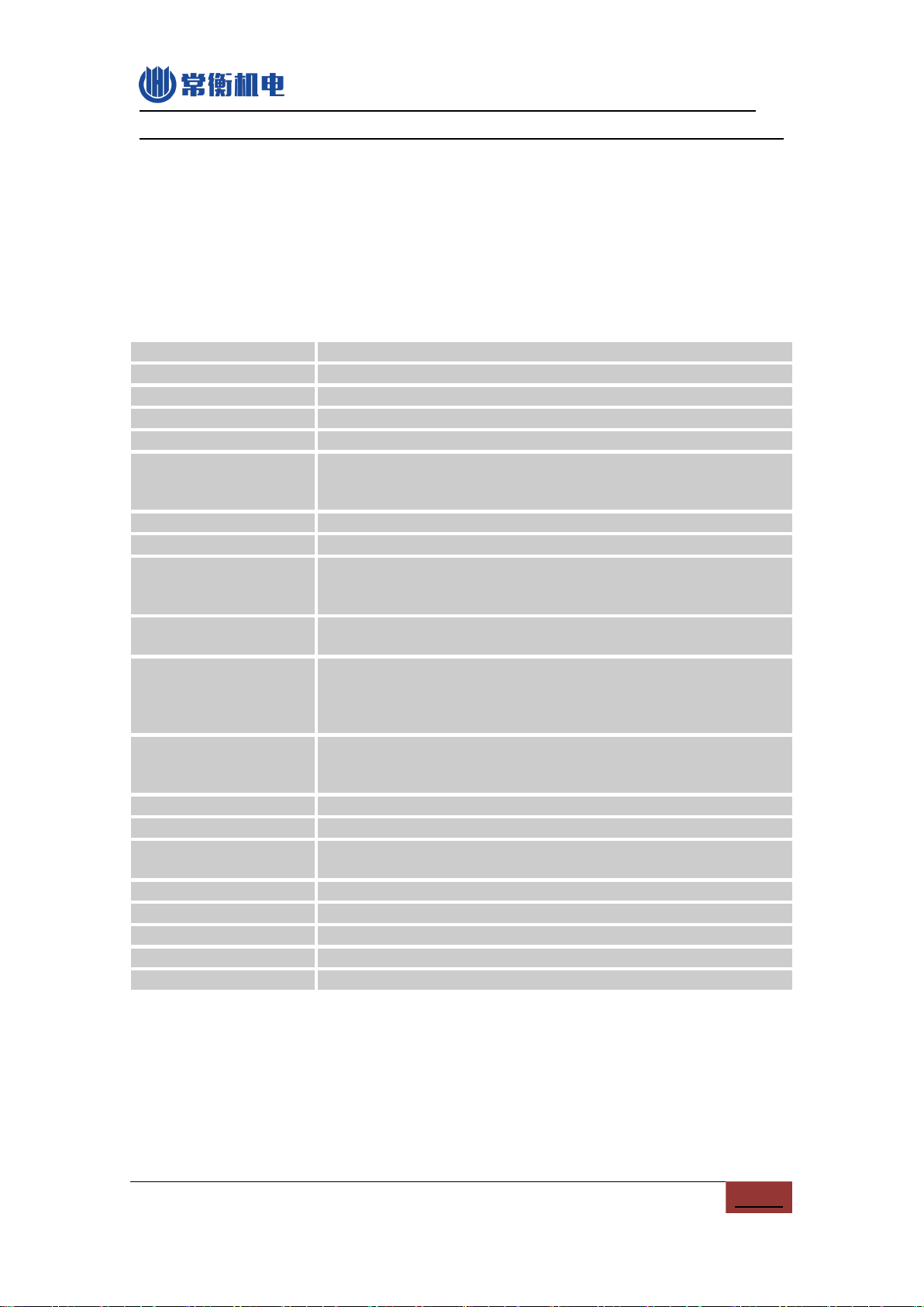
2.MAIN PARAMETERS.........................................................................................................................2
2.1.CHM-T36VA................................................................................................................................... 2
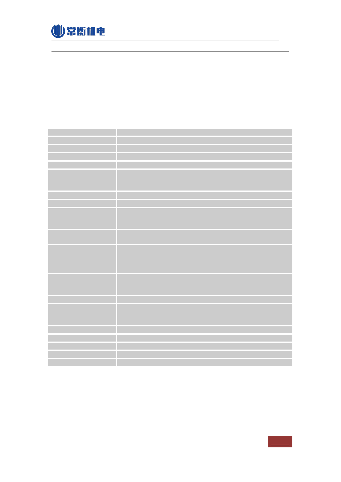
2.2.CHM-T48VA................................................................................................................................... 3
2.3.CHM-T48VB...................................................................................................................................3
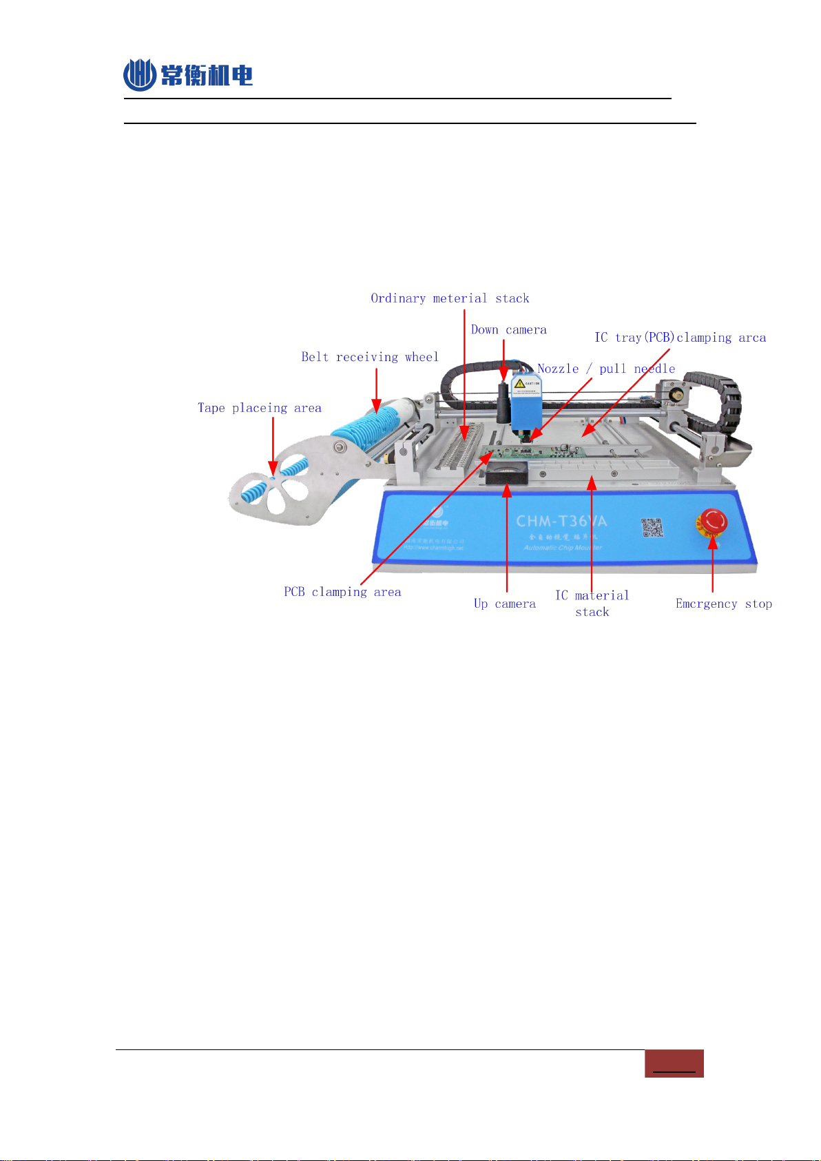
3.MACHINE PROFILE.......................................................................................................................... 5
3.1.CHM-T36VA................................................................................................................................... 5
3.2.CHM-T48VA................................................................................................................................... 6
3.3.CHM-T48VB...................................................................................................................................7
4.INSTALLTION MACHINE....................................................................................................................... 9
5.START..................................................................................................................................................... 9
6.RUN....................................................................................................................................................... 10
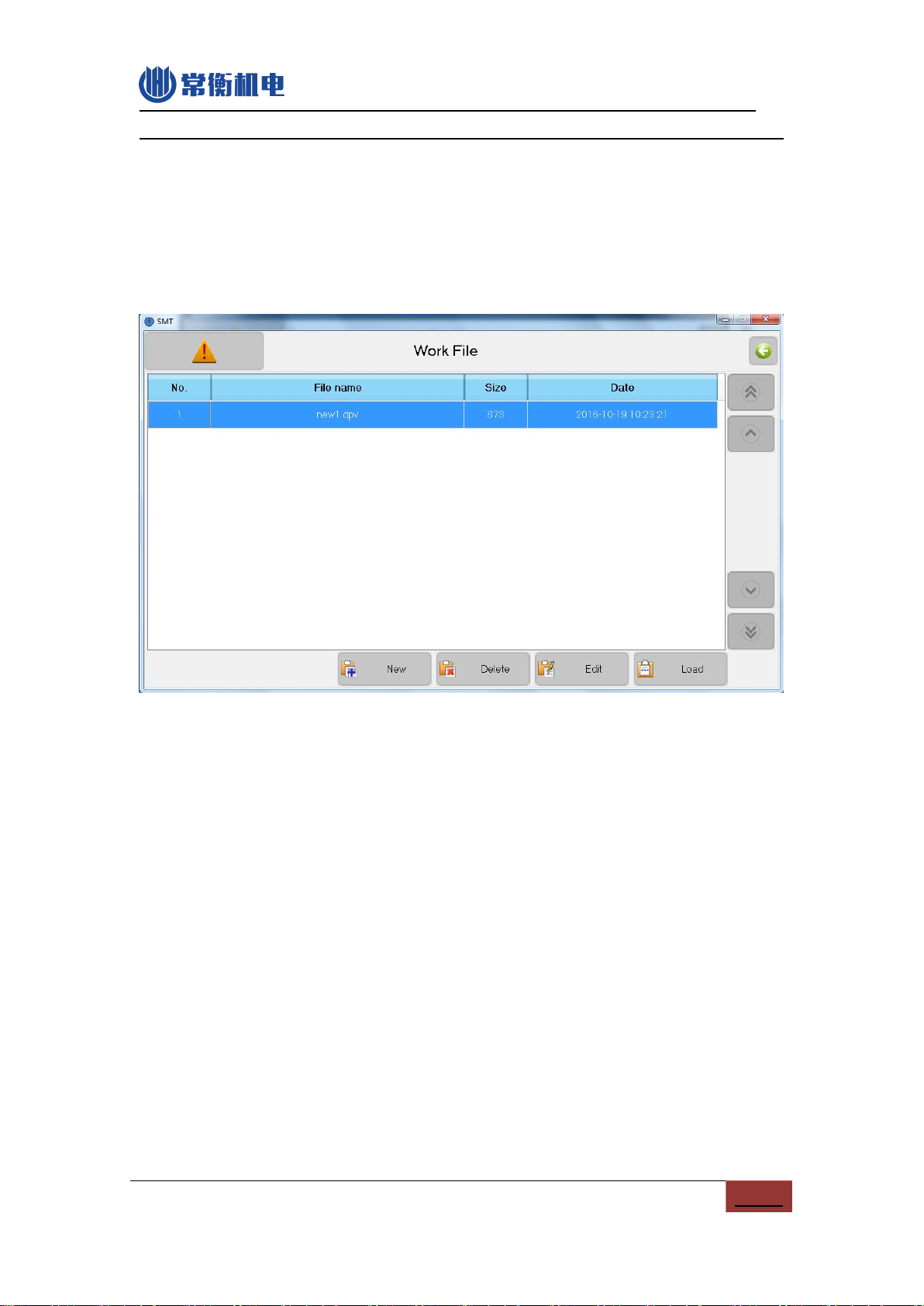
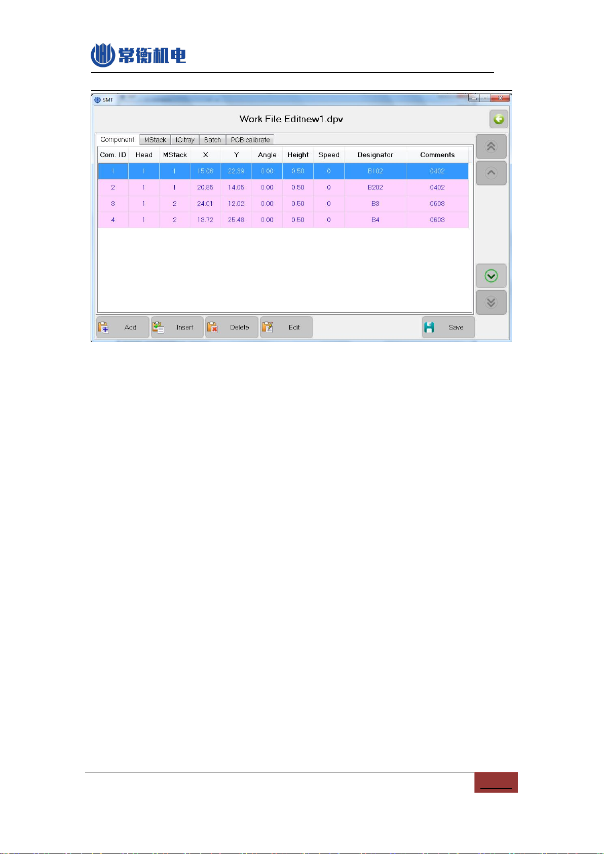
6.1. EDIT WORK FILE...........................................................................................................................10
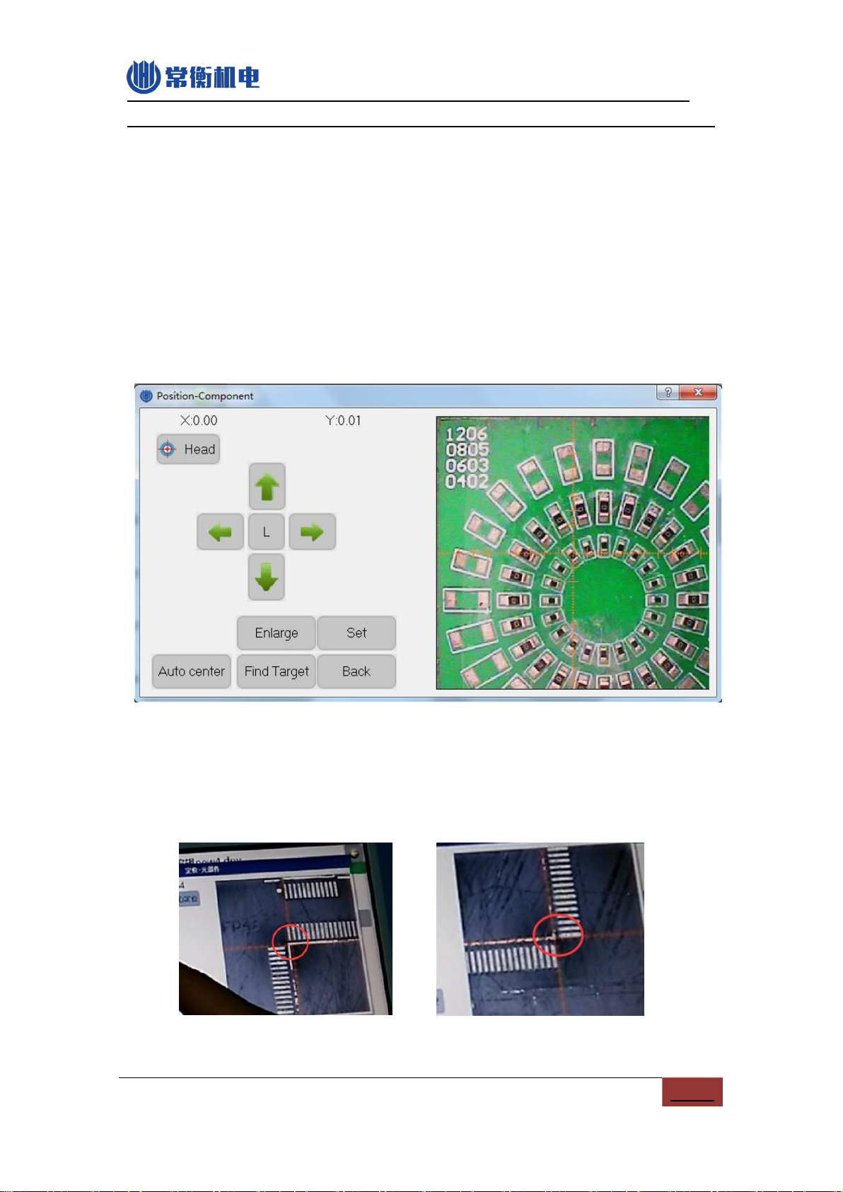
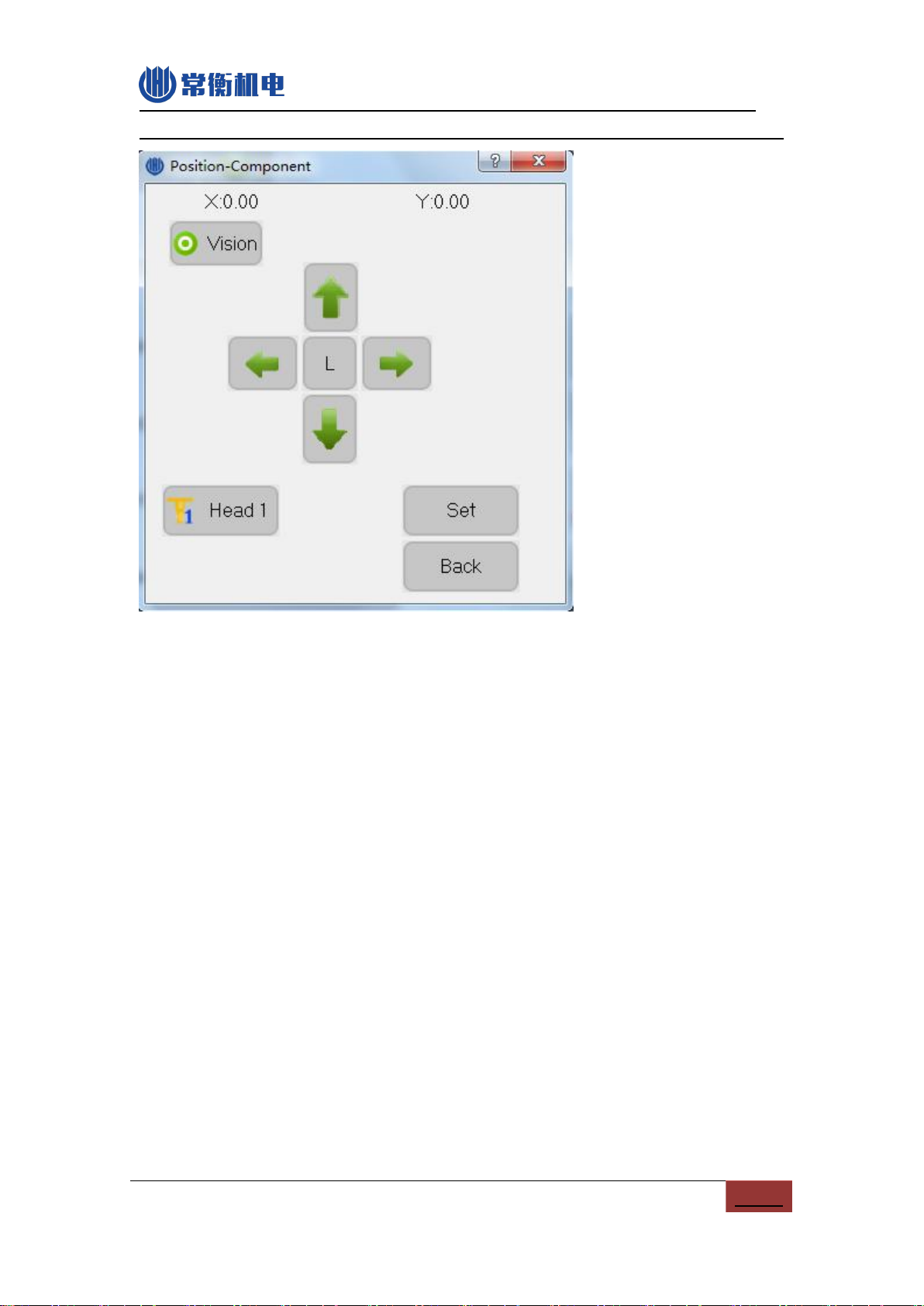
6.1.1.Component edit
................................................................................................................. 11
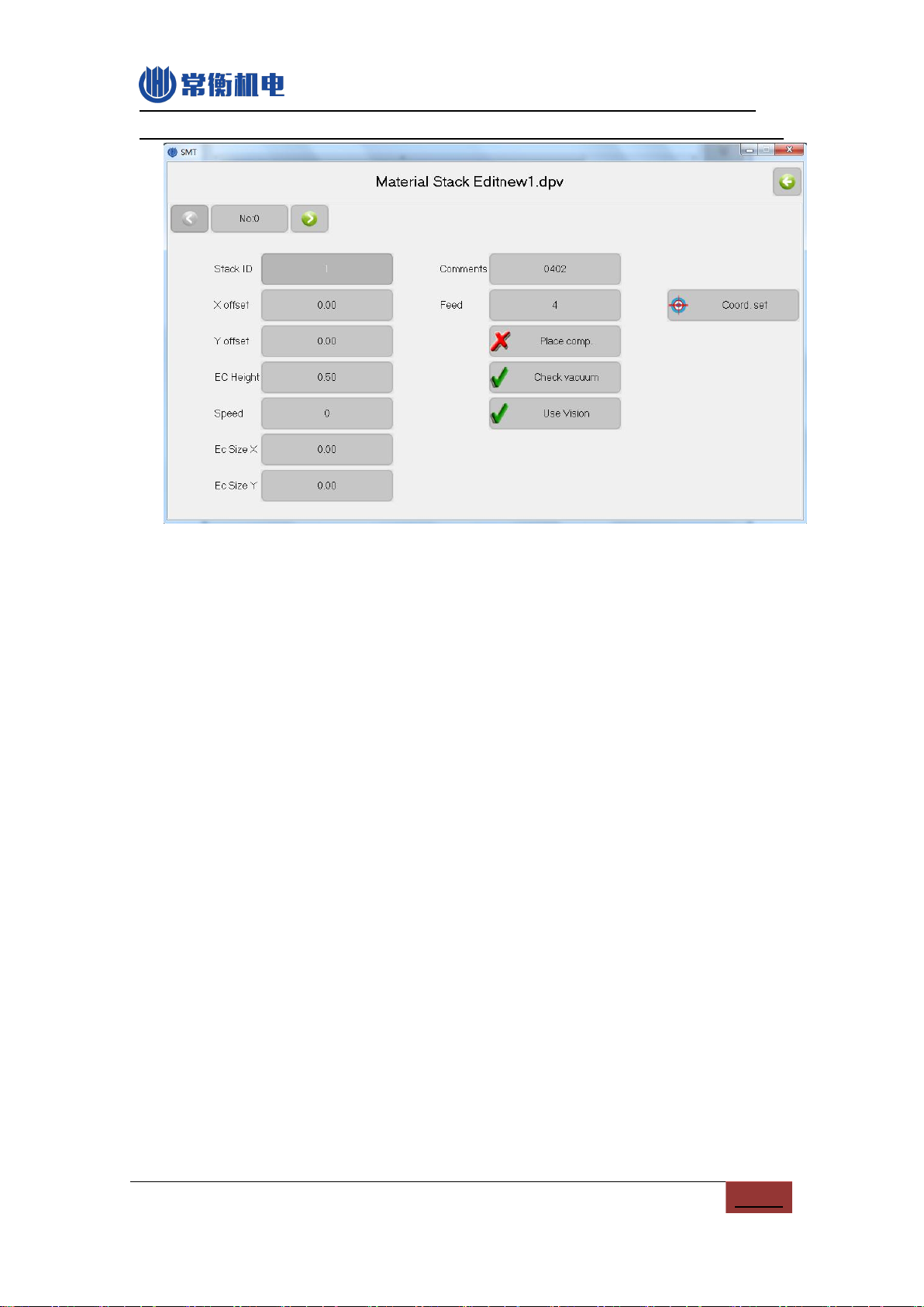
6.1.2.Material Stack edit
....................................................................................................... 15
6.1.3.Batch
................................................................................................................................... 18
6.1.4.IC Tray edit
..................................................................................................................... 20
6.1.5.PCB Calibration
............................................................................................................... 22
6.2.LOAD WORK FILE.............................................................................................................................24
7.TEST..................................................................................................................................................... 27
8.SET....................................................................................................................................................... 29
8.1.SYSTEM SET.................................................................................................................................... 30
8.2.VACUUM DETECTION SET................................................................................................................... 32
8.3.BACKUP/RESTORE..............................................................................................................................34
9.FILE..................................................................................................................................................... 36
9.1.GENERATE CSV FILE....................................................................................................................... 36
9.1.1.By Altium Designer
.........................................................................
错误!未定义书签。
9.1.2.By Protel
...........................................................................................
错误!未定义书签。
9.2.FILE CONVERT.................................................................................................................................38
9.2.1.Material Stack
................................................................................................................. 39
9.2.2.Components list
............................................................................................................... 40
9.2.3.Batch
................................................................................................................................... 41
10.LOG..................................................................................................................................................... 43
11.SYSTEM LOG....................................................................................................................................... 45