manuals.online logo
Brands
  1. Home
  2. •
  3. Brands
  4. •
  5. Capcom
  6. •
  7. Pinball Machine
  8. •
  9. Capcom Breakshot User manual

Capcom Breakshot User manual

Popular Pinball Machine manuals by other brands

Stern Pinball Heavy Metal Service and operation manual

Stern Pinball

Stern Pinball Heavy Metal Service and operation manual

Dr Pinball Personal DMD Installation and usage instructions

Dr Pinball

Dr Pinball Personal DMD Installation and usage instructions

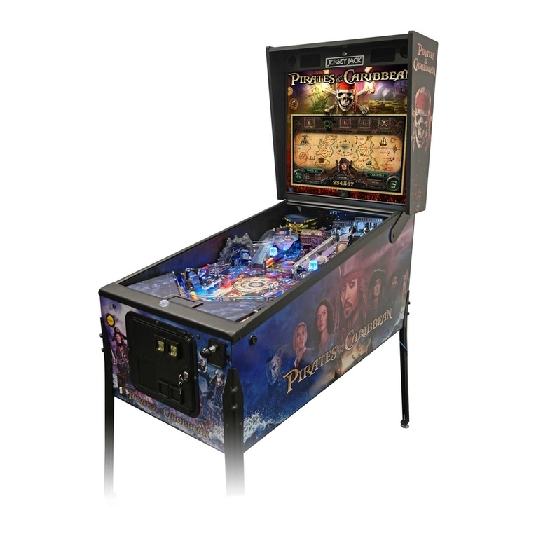
Jersey Jack Pinball Pirates of the Caribbean Operation manual

Jersey Jack Pinball

Jersey Jack Pinball Pirates of the Caribbean Operation manual

Swinks Stern Pinball Ghostbusters manual

Swinks

Swinks Stern Pinball Ghostbusters manual

LOBSTER The Pickle owner's manual

LOBSTER

LOBSTER The Pickle owner's manual

Dutch Pinball The Big Lebowski Pinball Technical support

Dutch Pinball

Dutch Pinball The Big Lebowski Pinball Technical support

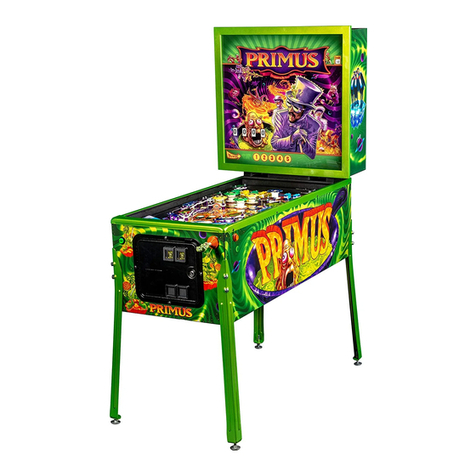
Stern Pinball PRIMUS Service and operation manual

Stern Pinball

Stern Pinball PRIMUS Service and operation manual

Stern Pinball JAMES BOND 007 PRO Service and operation manual

Stern Pinball

Stern Pinball JAMES BOND 007 PRO Service and operation manual

Stern Pinball JURASSIC PARK Setup guide

Stern Pinball

Stern Pinball JURASSIC PARK Setup guide

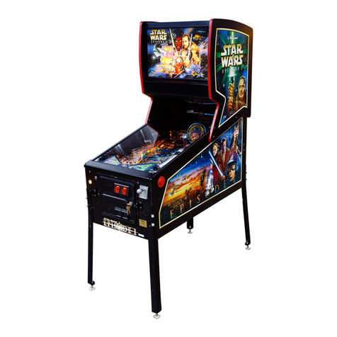
Williams Pinball 2000 Star Wars Episode I Operation manual

Williams

Williams Pinball 2000 Star Wars Episode I Operation manual

HOMEPIN Thunderbirds Unpack & Setup

HOMEPIN

HOMEPIN Thunderbirds Unpack & Setup

Stern Pinball JAWS Service and operation manual

Stern Pinball

Stern Pinball JAWS Service and operation manual

DP THE BIG LEBOWSKI Quick setup guide

DP

DP THE BIG LEBOWSKI Quick setup guide

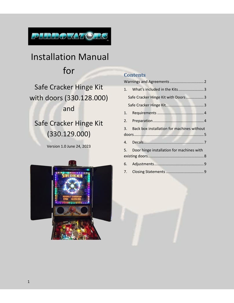
Pinnovators 330.128.000 installation manual

Pinnovators

Pinnovators 330.128.000 installation manual

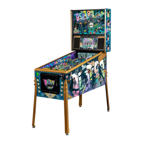
Stern Pinball The Beatles Operation and parts manual

Stern Pinball

Stern Pinball The Beatles Operation and parts manual

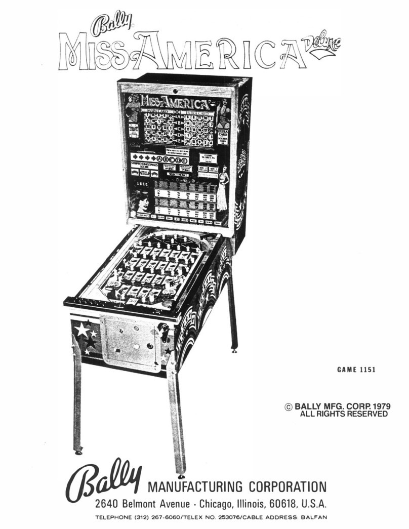
Bally Miss America Deluxe Maintenance service manual

Bally

Bally Miss America Deluxe Maintenance service manual

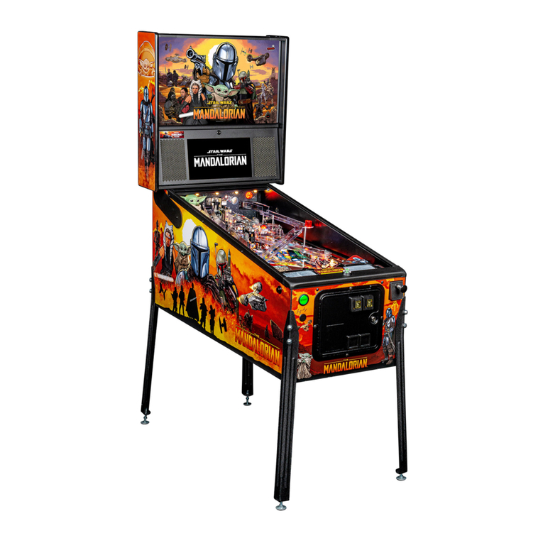
Stern Pinball THE MANDALORIAN PRO Setup instructions

Stern Pinball

Stern Pinball THE MANDALORIAN PRO Setup instructions

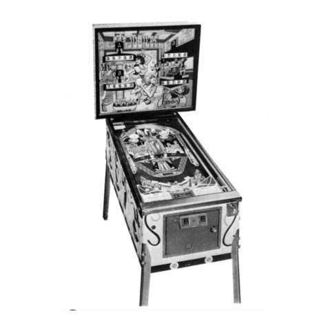
Williams Electronics JUBILEE instruction manual

Williams Electronics

Williams Electronics JUBILEE instruction manual

manuals.online logo
manuals.online logoBrands
  • About & Mission
  • Contact us
  • Privacy Policy
  • Terms and Conditions

Copyright 2025 Manuals.Online. All Rights Reserved.

~'COIHOP,
MC.
BREA
KSMOTm
GAME
SPECIFICATIONS
k
CHARACTERISTIC
DESCRIPTION
I
ELECTRICAL INPUT
I00
to 115V
AC
5aoHZ
8
AMPS
RATINGS
200
to 230V AC
W6OHZ
4
AMPS
CIRCUK Slow-Blofuses, Vari~torSurge Protection, IEC-TypeGroundedReceptacle
PROTECTION
SHIPPING CARTON Height: 55-1/2"(1.41
M)
Width:
30-1/2"(0.77M)
Depth:
30-1/2"(~.77M)
INFORMATION
Weight
240
Pounds (1
08.6Kg)
PRODUCT FCC,
Part
15, Class
A
DigitalDeice
APPROVALS
CE
Marking
AUDIO SYSTEM MPEG Digital
1
ChannelMonoOutput (Left, Center, Right)Ratedat 10WattsRMS
*
Two
4"
2-way
Speakerstor Mid
&
High
Frequencies
One
8"
Bass
Speaker
for Low Frequencies
DISPLAY
128
X
32
Character
DotMatrix
COIN DOOR
Standard:
2
CoinAcceptors Optional: Additional
2
Coin
Acceptor or
Bill
Acceptor
OPERATOR Audio: Volume Control
fw
Sound
Effects,
BackgroundSounds, Attract Sounds
ADJUSTABLES Visual: Standard or
Custom
Display
Messages
Coinage:
U.
S.
Standard; CustomConfigurationfor ForeignCurrencies
Play
Mode:
Free
Play,
Tournament,
and
Game
DiffiiuttyLevel
Game
Play ReplayPercentage,MatchCredits, Game
Restart
PasswordProtection:
3
Levelsof
Security
SPECIALSOFTWARE 475IndividualAudits *11Self-Test
Modes
.Adjustable
FlipperStrength
FEATURES
%
InternalDiagnostic Levels *Automated
Software
Troubleshooting
CABINET DIMENSIONS
NOTE:
DIMENSIONS
DO
NOTINCLUDE
CABINET PROTRUSIONS,
SUCH
AS
THE
BALL
SHOOTER, COlN
DOOR,
FLIPPER
BUTTONS,
OR
BACKBOX
LATCH.
h
L
-@COIN-OP,
INC
.
BREA
KSHOT~
TABLE OF CONTENTS
DESCRIPTION PAGE
Installation
&
Setup
...........................................................................................................................................................
1
GameRules
.........................................................................................................................................................
5
Menu System
Menu System Description
..................................................................................................................................
18
Audits Data Table
...............................................................................................................................................
21
Game Adjustments
..............................................................................................................................................
24
...............................................................................................................................................
Game Diagnostics
-33
...................................................................................................................................................
Reset Functions 41
Reports
..........................................................................................................................................................
-42
Redemption
......................................................................................................................................................
1
Component Parts Identification
&
Service Parts Listing
Cabinet
&
Backbox Parts Identification
..............................................................................................................
54
Power Driver Board
...........................................................................................................................................
-56
Sound Board
.......................................................................................................................................................
-60
CPU Board
.........................................................................................................................................................
-62
Display Power Supply Board
..............................................................................................................................
64
Interface Board
...................................................................................................................................................
-65
Diode Board
........................................................................................................................................................
66
Lamp Boards
.................................................................................................................................................
68
Cabinet, Backbox,
&
Playfield Lamps
..........................................................................................................
70
Playfield Rubber Rings
.......................................................................................................................................
72
.........................................................................................................................................
Playfield Ball Guides 73
Playfield Posts
....................................................................................................................................................
-74
.............................................................................................................................................
Switches and Optos 78
........................................................................................................................................................
Opto Boards 79
Solenoids and Flashers
........................................................................................................................................
80
Playfield Plastics
.................................................................................................................................................
82
Playfield
-
Mechanisms
.......................................................................................................................................
85
Troubleshooting Guide
Power-up Problems
...........................................................................................................................................
104
Coin Door Problems
............................................................................................................................................
105
Dot Matrix Display Problems
.......................................................................................................................
106
..................................................................................................................................................
Sound Problems 107
Playfield Problems
.
Mechanical
........................................................................................................................
108
Playfield Problems
.
Solenoids
...........................................................................................................................
109
Playfield Problems
.
Switches
.............................................................................................................................
110
....................................................................................................
Illumination Problems
-
Playfield
&
Backbox 111
Schematic Diagrams
I
Proprietary and confidential information. not
to
be
disclosedor copied without the express permissionof
CAPCOMa COIN.OP
.
INC
.
I
1
'3NI 'do-NI03@M03dV3
JO
uo!ssy~adssa~dxa
aq
)now!m pa!doj
JO
pasops!p
aq
4
IOU
'uo~~eur~o~u![eguapguojpue .hZJa!JdoJd
I
-1olnqgslpamo3de3
1~301
~noL,3e,uo3 '8ulsslm an(s)md Lue
JI
-swdandsse papnl3u~ansJaqlo a1p.p awe2 aqljo L[qurasso
JOJ
paqnba~am sued amog -~au!e,uo3awe%aqljo xoq %uppedaql ul papnpu~ansmd
%U~MOIIOJ
aqL
8) Install one hex nut (A) half-way up on each
leveler. Then insert levelers into each leg and turn
until they contact the stop nut. Using a second nut
(B), thread onto each leveler from inside the leg and
tighten (see Figure 6).
15)Attach lock washer and flat washer to thumb
screw and fasten to cabinet tee nuts (see figure 8).
Tighten firmly.
THUMB SCREW
FLAT
WASHER
FIGURE
6:
INSTALLING LEVELER ON LEG
9) Carefully lift the front of the cabinet and place
on a sturdy support. Attach the front legs using two
acorn-head bolts. Tighten bolts firmly
(see Figure 7).
FIGURE
7:
INSTALLINGLEGS ON CABINET
10)Carefully lift the rear of the cabinet, place on
a
sturdy support, and attach the legs using the
supplied bolts. Tighten firmly.
P
1)
At the rear of the cabinet, connect AC line cord
to receptacle. Install cover plate, bushing, and
screws.
12) Using two or more people lift the game and
move to intended play area. Do not slide legs on
floor.
13)Insert key into the lock at the top of the backbox
and turn fully clockwise. Lift up on backglass and
swing out towards front of game. CAREFULLY
remove backglass and set aside.
14)Lift up on latch and open the lamp door. Swing
door completely open. Open display panel by
pushing latches, located above the speaker
enclosures, out towards the sides of backbox.
FIGURE
8:
INSTALLINGBACKBOX LOCKING HARDWARE
16)Check that all fuses, connectors, lamps, and wire
harnesses are fully seated..Tighten any loose
fasteners snugly. Do not overtighten.
17)Close and latch both sides of the display panel;
then close and latch the lamp door. Re-install the
backglass and lock the backbox.
18)Place a level in position "A" on the playfield glass
(see Figure 9). Adjust the rear leg levelers, as
required, to obtain zero degree(OO)balance. Move the
level to position "B" and repeat front
&
rear
adjustments until cabinet appears level. Move the
level to position "C" and adjust front andlor rear leg
levelers to obtain a 6-112" incline. Tighten leg leveler
nuts firmly.
0
DEGREES
&4
FIGURE
9:
CABINETLEVELING
Page
2
Proprietary and confidential information, not to be disclosed or copied without the express permissionof CAPCOMB COIN-OP, INC.
-@COIN-OP, INC.
BREA
KSHOTTM
19) Remove the handrail by opening the coin door
and releasing the thumb latch (see Figure 10):
I
I
FIGURE10: REMOVING HANDRAIL
20) Remove playfield glass by sliding down and out
of armor guides. CAREFULLY set glass aside.
21) Push thumb latch to the right to release
playfield. Lift playfield straight-up until it reaches
the locked position. Verify that solenoids,
connectors, lamps, and harnesses are fully seated.
Tighten any loose fasteners snugly. Do not
overtighten.
22) Locate plumb bob parts. Install thumbscrew
into threaded hole on lead weight. Insert hook wire
into tapered end of lead weight. Raise wire
&
weight up into bottom tilt bracket and hang from top
bracket. Adjust and tighten screw firmly
(see Figure 1I).
FIGURE 11: PLUMB BOB TILT ASSEMBLY
23) Lower the playfield into the cabinet. Ensure
that cables are not pinched when playfield is seated.
24) Re-install the handrail by engaging the thumb
latch to the right (see Figure 12).
n
c
AND
TO RIGHT
P606W
FIGURE 12: INSTALLING HANDRAIL
A
Make sure your game is locked. Press down
on the handrail until you hear a click.
25) Connect AC line cord to power outlet. Route cord
away from foot traffic. Turn the game power ON
(switch is under cabinet near right front leg).
26) Open the coin door. Dot matrix display will show
the system menu. Follow directions in this manual for
changing factory settings.
27) Refer to the TROUBLESHOOTING GUIDE
section of the manual for assistance in locating faults,
clearing errors, etc.
28) Upon completion, system menu should report
"FOUND: 0 ERRORS, 0 INFO" to indicate the game
is ready for use.
29) Install required number of balls.
30) Close the coin door. Insert currency or tokens as
necessary. Press the START button. Game should
begin.
31) Clean both sides of playfield glass. Install glass.
Install handrail. Ensure that lever snaps in and locks.
32) Open coin door and retrieve currency or tokens.
Set custom messages, difficulty, pricing, replays, etc.
33) Reset all counters to zero. Close and lock coin
door. Ensure that the backbox is locked.
Proprietary and confidential information, not
to
be disclosed or copied without the express permission of CAPCOMa COIN-OP, INC.
Page
3
CNB~EJ@COIN-OP,
INC.
BREA
KSHOT~
PLAYFIELD
GAME
FEATURES
TOP LANES
INDICATOR LAMPS
TOP LANES
-
STAR BUMPERS-
LEFT SUPER CUE,
CAPTIVE BALL-
LEFT CENTER
STAND-UPTARGET-
LEFT STAND-UP
TARGET (HIDDEN)
-
:FT DROP TARGETS
-
_EFTRETURN LANE-
LEFT OUTLANE-
LEFT SLINGSHOT-
RlGHT SUPER CUE
RlGHTSTAND-UP
TARGET (HIDDEN)
RlGHT DROP TARGE
CENTER POCKETS
CENTERPOST
UPPER RlGHT FLlPP
RlGHT CENTER
STAND-UP TARGET
AWARD LIGHTS
BONUS SAUCER
NINEBALLGAME
BONUS RACK
RlGHT RETURN LAN
RlGHT OUTLANE
SHOOT AGAIN
,
-.---.,
ITS
'ER
Page
4
I
Proorietarv and confidential iniorrnabon. not to
bf
disclosedor cooied without the enoress ~errnissionoi CAPCOMO COIS-OP. INC.
I
n
a
.z
z?
e
20
s
U
E
h
a
&Q)
s
s
ma
bl)
.E
2
3
3
BREA
KSHOTm
points to the End-of-Ball bonus. Once all the Solids or Stripesballs have been collected, the eight ball is
spotted. Making the eight ball shot wins the Eightball game and begins Nineball.
@
@
@
@
@
@
are located above the top lanes. Making the corresponding top lane,
when one of these balls is flashing, collects that ball.
@
and
@
are located at the left center standup target.
0
and
@
are located at the right center
standup target. Hitting these standup targets collects these balls.
@
and
@
are located at the left drop target bank. and
@
are located at the right drop target
bank. Initially, the ball indicator lamps are lit steady. Completing either drop targets will "spot" the ball,
causing the appropriate ball lamp to flash. Hitting the standup target behind the drop target collects the
indicated ball.
@
The is located at the Bonus Saucer on the right side of the playfield. The eight-ball is qualified
("spotted") after all Solids or Stripes have been collected. Shooting the bonus saucer collects the
eightball, winning the Eightball game and begins Nineball.
In addition to the shots mentioned above, balls can be collected by repeatedly shooting the bankshot
orbit (see Bankshot Orbit),by shooting the Left and Right Super Cue (orbits) (seeLeft Super Cue and
Right Super Cue), and shooting the center pockets saucers (see Center Pockets).
NINEBALLGAME
The Nineball game is indicated by the Nineball game light flashing. It flashes once for each time the
Nineball game has been played during the current coin (including buy-ins).
8
When the Nineball game is started, the flashes in the bonus rack.
@
through
@
must be
collected, in order, to win the Nineball game and begin Rotation (if the previous game was Eightball) or
Eightball (if the previous game was Rotation). When a ball is collected, it is lit in the bonus rack and the
next ball will be spotted (flashing) in the bonus rack. Collecting a ball scores 30,000 points and adds
10,000points to the End-of-Ball bonus.
During the Nineball game, both the left and right Super Cues (orbits) are lit. Shooting the left Super Cue
lane either directly, or by completing a right Super Cue (which feeds around to the left Super Cue lane),
spots a ball. The "Spots Next Ball" light will be flashing in the left Super Cue lane to indicate that the
Super Cues are spotting the ball.
Shooting the Captive Ball standup target spots one ball (see Captive Ball). Balls can also be collected by
repeatedly shooting the Bankshot orbit (see Bankshot) or by shooting the Center Pockets saucers (see
Center Pockets).
The current Nineball award is indicated by a flashing SPECIAL, POINTS, or EXTRA BALL light in the
center of the playfield. The first time the Nineball game is played, EXTRA-BALL and POINTS
alternate. Each sucessive Nineball game will then alternate between SPECIAL, EXTRA BALL, and
Page
6
I
Proprietary and confidential information, not to
be
disclosed or copied without the express permission of CAPCOMmCOIN-OP, INC.