Carbonheat Multiflex 20 User manual

Solutii de incalzire si degivrare
Multiflex 20 Manual de instalare/Installation instructions
-CABLU INCALZITOR PENTRU INSTALAREA IN SAPA GROSIERA DE INTERIOR SAU AUTONIVELANTA
NOTA! MULTIFLEX20 NU SE INSTALEAZA INTRE GRINZILE DE LEMN/CHERESTEA
NOTA! FOLOSITI UN ELECTRICIAN AUTORIZAT PENTRU INSTALAREA CABLULUI INCALZITOR
1. 1.Verificati daca materialul folosit este acelasi cu cel comandat de dumneavoastra.
2. 2.Verificati Izolația și rezistența cablului și comparați cu valorile din tabelul de mai jos. Toleranța este de ± 10%. Introduceți
valorile pe Certificatul de garantie..
3. Cand instalarea se face in sapa grosiera, spatiul normal intre buclele de cablu este de 12-15 cm in functie de necesarul
energetic calculate iar adancimea fata de suprafata finala trebuie sa fie de aproximativ 40-50 cm.In cazul sapei autonivelante,
distanta intre buclele cablului nu trebuie sa depaseasca 10/12 cm. si se astupa la o adancime de minimum 15 cm in sapa
autonivelanta.Pentru a avea un calcul cat mai exact a-l distantei intre bucle, impartiti suprafata de instalare la lungimea
cablului.
4. Daca se folosesc benzi de fixare, asigurativa ca sunt foarte bine prinse.
5. Este interzis sa taiati cablul cald incalzitor.Numai cablul rece poate fi taiat.Cablul cald este produs la o lungime integrata
exacta si doar la un singur capat se poate alimenta la tensiunea de 230v.
6. Planificati intinderea cablului astfel incat cablul rece si capatul cablului cald sa nu ajunga sub zona de dus.
7. A. Intinderea pe o suprafata de beton existent:
Derulati cablul si fixatil cu adezi sau lipici special la aproximativ10/12 cm in bucla .Daca folositi lipici special tineti-l pana lipiciul
se intareste. Distanta care se lasa intre cablu incalzitor si perete trebuie sa fie aproximativ jumatate din distant din bucla
(5/6cm).Faceti la fel si cu urmatoarea bucla.Acelasi principiu se foloseste si in cazul in care folositi benzi de fixare in l oc de lipici
special.
B. Instalarea pe plasa de armare in sapa grosiera:
Derulati cablul incepand cu doza de legatura.Cablul se prinde de plasa de armare cu benzi de fixare.Distanta intre buclele
cablului trebuie calculate bine pentru a nu aparea diferente de puteri/m2 in pardoseala.Cablul rece trebuie si el incastrat in
sapa.Folositi o sapa cat mai umeda care curge usor pentru a nu se forma bule de aer intre cablu si sapa.Nu asezati cablul
incalzitor peste alte cabluri de current, tevi sanitare sau produse inflamabile.
8. O instalare de cablu incalzitor nu trebuie sa fie asezata peste alta instalare de cablu incalzitor. Distanta intre ele este de minim
50mm
9. Cablul incalzitor nu trebuie sa treaca peste rosturile de dilatare.
10. Masurati din nou izolatia si resistenta[ohm] cablului incalzitor inainte si dupa turnarea sapei. Este o masura de siguranta
pentru a verifica daca turnarea sapei nu a afectat cablul incalzitor. Valorile trebuie trecute in Certificatul de Garantie.
11. Dupa Instalare si testare, cablul rece trebuie pozitionat in asa fel incat apa sa nu se infiltreze in el.
12. Temperatura din camera este controlata de unul din termostatele Ebeco/ Senzorul de pardoseala trebuie instalat intr-un tub
de COPEX ce se pozitioneaza in sapa intre doua bucle de cablu incalzitor la o distant de perete de minim 50 cm. Izolati capatul
copexului care intra in sapa.
13. Cablul incalzitor nu trebuie folosit cel putin 4 saptamani de la turnarea sapei, sau cu acordul producatorului.

Solutii de incalzire si degivrare
Multiflex 20 Manual de instalare/Installation instructions
- HEATING CABLE FOR INSTALLATION IN CONCRETE FLOORS INDOORS OR CONSERVATORIES
NOTE! MULTIFLEX 20 MUST NOT BE INSTALLED BETWEEN TIMBER JOISTS.
NOTE! A QUALIFIED TECHNICIAN MUST INSTALL THE HEATING CABLE.
1. Check that the supplied material corresponds with the delivery note.
2. 2. Measure the cable’s insulation value . Measure the cable’s resistance, see the values in the table below the value can very
with positive /negative 10%. Enter the values in the Guarantee Certificate.
3. When embedding in concrete the c/c (centre-to-centre) spacing is normally 12-15 cm and the cable is cast about40/ 50 mm
under the completed floor surface. In conservatories the c/c spacing is usually 12-15 cm. Using this reduced c/c measurement
(<15 cm) the cable can also be laid in a layer of screed with a minimum depth of 15 mm, if the substrate is concrete. In order to
obtain more exact c/c spacing divide the installation area by the length of the cable
4. If fixing strips are used, secure this square to the cabel's installation
5. You must not shorten the heating cable. Only the cold cable may be shortened. The cable is manufactured with an integrated
return, i.e. only one end (cold cable) needs to be connected to 230V
6. Plan the layout so that the cold cable splice and the end termination do not end up in the shower area.
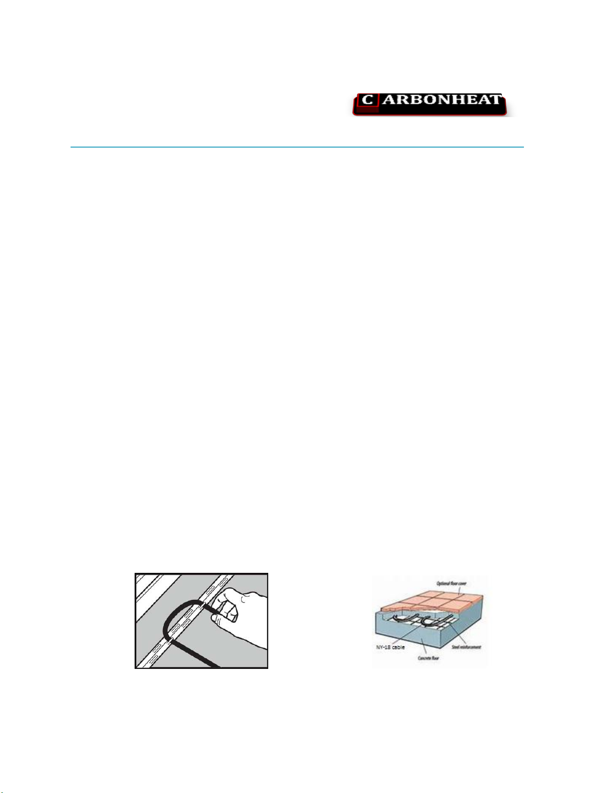
7. A. Laying on existing concrete substrate:
Pull out the first loop of the cable and fix it with glue about 10/12 cm from the bend. Hold the cable in the glue until the glue
has hardened. The distance between the cable and the wall should be approx. half the c/c-distance. Do the same with the next
loop. The same principle applies for laying with fixing strip or on reinforcement.
B. Embedding in concrete slab:
Roll out the cable; start by the connection box. The cable is fixed to the fixing strip (E 89 603 91 or E 89 609 68) or secur ed to
the reinforcement bar using cables ties or the like. By the outer wall or windows it may be beneficial to lay the cable in half the
c/c spacing (c/c = 100 mm) to minimize any draught. The cable’s cold cable joint must be cast into the concrete. Use concrete
that flows easily, so that there is good contact between the cable and the concrete and so that no air pockets are formed.
Never lay the cable directly over insulation or combustible material.
8. One cable section must not lie over another section or be crossed. Minimum spacing 50 mm
9. The heating cable must not cross expansion joints in the concrete.
10. The cable should be insulation and resistance measured once again both before and after it has been embedded. This is to
ensure that the cable has not been damaged during laying. The values has to be entered in the Guarantee Certificate.
11. After laying and testing, the cold end of the cable must be positioned so that water cannot penetrate into the cable.
12. The room temperature is controlled with one of Ebeco´s EB-Therm thermostat. The sensor should be placed inside a conduit
pipe, which is then laid in the screed or concrete between two runs, at least 0.5 m from the wall. Tape over the end of the
conduit
13. The cable must not be used for at least 4 weeks after the complted jointing work, or according to the manufacturer’s
instructions.
Table of contents
Languages:
Popular Cables And Connectors manuals by other brands

OUNEVA
OUNEVA VC02-0004 installation guide

PureEdge Lighting
PureEdge Lighting Nova NCM-SP Series installation instructions

Staubli
Staubli PV-KST4 UR Series Assembly instructions

Acuity Brands
Acuity Brands Lithonia Lighting I-BEAM IBZACVH installation instructions

Microsoft
Microsoft High Definition AV Pack instruction manual

Vivanco
Vivanco USB PAR-N 23427 manual