CAREDirect Medserve User manual

CAREDirect | 7441 E Butherus Dr # 300 | Scottsdale, AZ 85260
caredirectllc.com | 480-751-1967 | info@caredirectllc.com
Medserve Installation Instructions

23570-1019 Rev B 2
TABLE OF CONTENTS
Preparation ..............................................................................2
Determine Mounting Location.................................................2
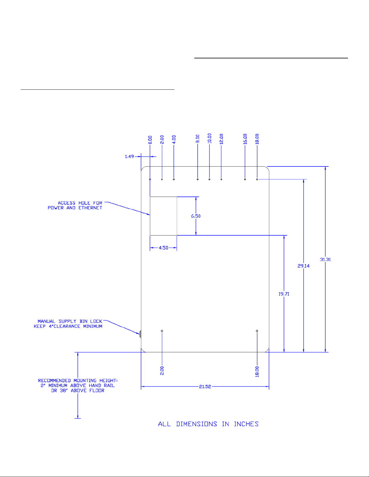
Figure A - Mounting Hole Locations.................................3
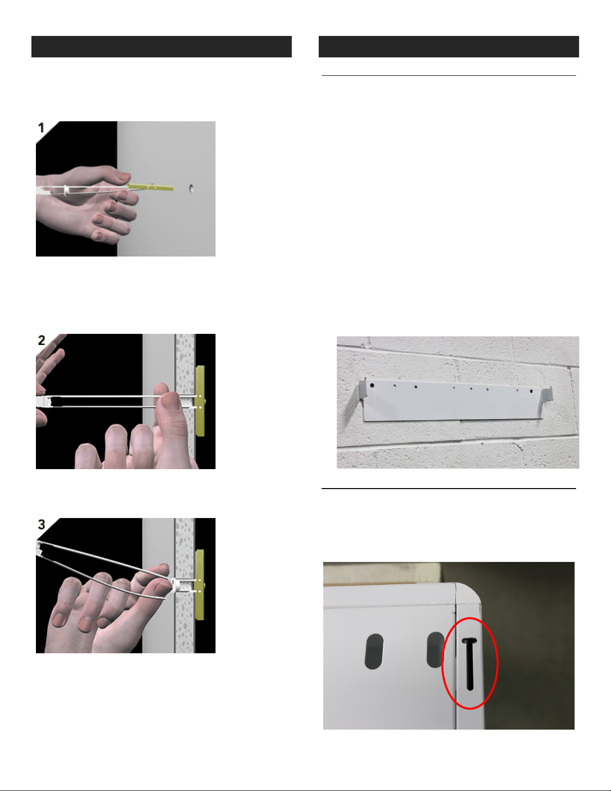
Snap-Toggle Bolt Installation ...................................................4
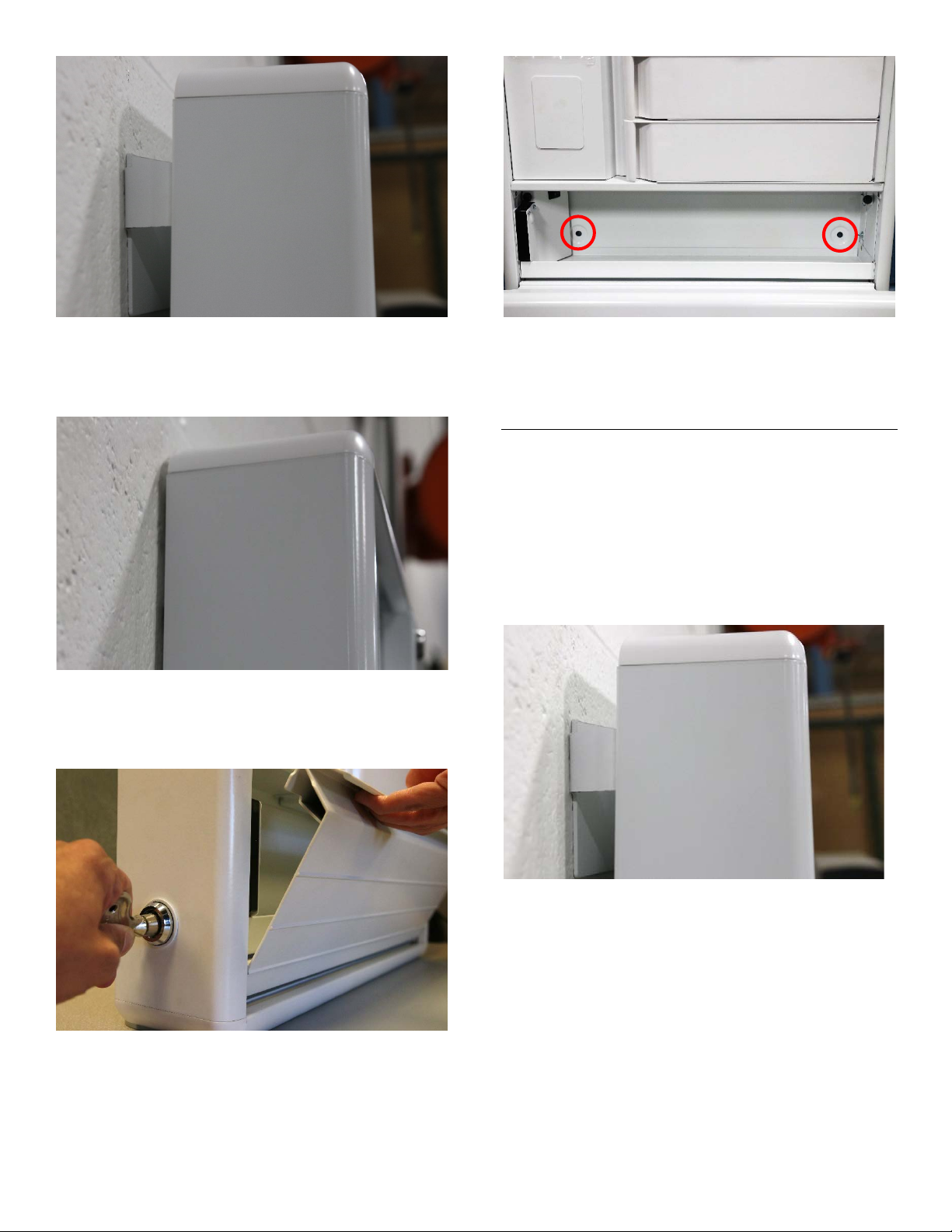
Mounting the Cabinet..............................................................4
Optional Connections ..............................................................6
Ethernet ...........................................................................6
Routing Cables Outside the Cabinet ................................8
Operation Manual and Software .............................................8
PREPARATION
TOOLS REQUIRED
•Hand drill with 1/2” drill bit
•Phillips screw driver
•Level
•Pencil
PARTS INCLUDED
•Mounting bracket
•AC Adapter
•Mechanical override key
•(2) Duplicate keys for cassette lock
•(5) ¼-20 Heavy duty Snap-Toggle bolts
•(5) ¼-20 x 2” screws
INSTALLATION WARNINGS:
•Read the entire instruction manual before beginning any
installation or assembly.
•The installer must verify that the entire wall safely
supports the combined weight of all the attached
equipment and hardware.
•Improper installation of this product may cause extensive
property damage or serious personal injury, either during
or after installation.
DISCLAIMER:
•The manufacturer and/or distributor will bear no
responsibility for any damages of any kind arising from
any improper installation of this product.
•Because wall construction varies widely and the ultimate
method of mounting/installing is out of the manufacturers
or distributors control, it is imperative that the installer
consult with local engineering, architectural, or
construction personnel to ensure the wall is constructed
properly to code and will handle the applied load.
•Through improper installation or excessive applied load
the cabinet can be pulled out of the wall by force, taking
with it a large section of drywall. In no way will the
manufacturer or distributor be held liable for any damage
to the cabinet, property or personal injury should an
outside force either intentionally or unintentional be
applied to the cabinet causing it to pull off the wall.
SAFETY WARNINGS:
•California installations may require specific anchorage and
additional supports. Check with local authorities for codes
in your area. Other seismic states will have similar
regulations.
•Prior to drilling verify the location of any electrical wiring
with in the wall. An electrical short can seriously injure
and create a fire hazard both during and after installation.
•Ensure that all electrical work (for instance, installing
power outlet) is conducted by a licensed electrician and
adheres to all applicable codes and guidelines.
DETERMINE MOUNTING LOCATION
MOUNTING HEIGHT
The recommended mounting height is 38 inches to the
bottom of the cabinet. If the cabinet is mounted above a
handrail, ensure that there is at least 2 inches of clearance
between the top of the hand rail and the bottom of the
cabinet (see Figure A).
INLET FOR POWER AND ETHERNET
An access hole in the back panel allows a power outlet and
ethernet connection to be hidden inside the cabinet after
mounting. If desired, install an AC power outlet and/or
ethernet connection inside the access hole area indicated on
Figure A.

23570-1019 Rev B 3
If a power outlet is not installed in the designated area,
power may be connected outside the unit as described in the
section titled Routing Cables Outside the Cabinet.
Ethernet is not required for network connectivity. The
onboard computer has an integrated Wi-Fi adapter to
connect to wireless networks.
CLEARANCE FOR MANUAL OVERRIDE
A mechanical override lock for the supply bin is located on
the left side of the cabinet. Keep a minimum of 4” clearance
from the left side of the cabinet to the nearest object to
ensure the lock may be reached and operated if necessary.
See Figure A.
MOUNTING HARDWARE
Use the included Snap-Toggle bolts to mount the cabinet to
drywall or to steel studs. #14 x 3” long wood screws are
recommended for mounting the unit to wood studs. Note:
five Snap-Toggle bolts are included, but only four are needed
for installation.
FIGURE A - MOUNTING HOLE LOCATIONS

23570-1019 Rev B 4
SNAP-TOGGLE BOLT INSTALLATION
Drill a 1/2" (Ø13mm) hole. Hold metal channel flat alongside
plastic straps and slide channel through hole. Minimum
clearance behind wall: 1-7/8" (48mm).
Hold ends of straps between thumb and forefinger and pull
toward you until channel rests flush behind wall. Slide plastic
cap along straps with other hand until flange of cap is flush
with wall.
Snap straps at wall by pushing side to side, snapping off
straps level with flange of cap.
MOUNTING THE CABINET
SECURE THE MOUNTING BRACKET TO THE WALL
•The included mounting bracket has 8 holes, but only two
are required for mounting. Choose two holes to mount
the bracket. THE TWO HOLES SELECTED SHOULD BE AT
LEAST 14 INCHES APART.
•Determine the location of the two mounting holes on the
wall using Figure A as a guide. Ensure that the chosen
locations are level and meet the minimum requirement
for hand rail clearance. Also ensure the holes are located
properly to incorporate a power outlet into the cabinet if
desired.
•Install a Snap-Toggle at each chosen hole location
following the instructions above.
•Secure the mounting bracket to the wall by passing the
included screws through the selected holes on the bracket
and into the Snap-Toggles that were previously installed.
ENSURE THE MOUNTING BRACKET IS LEVEL and tighten
the screws.
HANG THE CABINET TO LOCATE THE BOTTOM HOLES
Lift the cabinet onto the hooks of the mounting bracket.
Ensure the hooks pass through the slots on the back of the
cabinet.

23570-1019 Rev B 5
Push the cabinet towards the wall until it locks into place on
the hanging bracket. You should notice the cabinet drop
slightly once it locks into place.
Unlock the supply bin by using the included override key.
Push to insert the key and turn clockwise roughly 15 degrees.
Manually pull the supply bin door open.
Use a pencil to mark the location of the two bottom
mounting holes inside the supply bin.
Remove the cabinet by lifting it vertically and then pulling it
forward. Install two Snap-Toggles in the locations just
marked.
CONNECTING POWER THROUGH THE ACCESS HOLE
If connecting power through the access hole on the back
panel, follow these steps. Otherwise, proceed to the next
section.
Hang the cabinet on the hooks of the mounting bracket. Pull
the cabinet forward on those hooks so the backside of the
cabinet may be accessed.

23570-1019 Rev B 6
Connect the barrel plug of the power adapter to the dongle
that is present in the access hole. Plug the power adapter into
an AC outlet.
SECURE CABINET TO THE WALL
Push the cabinet towards the wall until it locks into place on
the hanging bracket. You should notice the cabinet drop
slightly once it locks into place. Ensure the top of the cabinet
is secure.
Open the supply bin and use the supplied screws to fasten
the cabinet to the Snap-Toggles that were previously
installed. Once finished, ensure that the cabinet is secure and
cannot be pulled away from the wall.
OPTIONAL CONNECTIONS
ETHERNET
To make an ethernet connection, the front access panel must
be removed. Power the cabinet, allow it to boot to the login
screen, and follow these steps to remove the cassette.
Enter the code 10597 and press the unlock icon.
On the next screen, press the unlock cassette icon and wait
for the cassette to unlock.
Remove the cassette from the cabinet by pulling on the
handle.

23570-1019 Rev B 7
Set the cassette aside. Remove the three screws that are now
visible on the access panel.
Pull the access panel from left to right to free the left side of
the panel.
Remove the access panel and rotate to expose the back. The
panel may be rested on the right side of the cabinet where
the cassette normally resides.
Plug your ethernet cable into the ethernet port located on
the underside of the computer.
When complete, replace the access panel. Ensure the tabs on
the left side of the panel fully insert into the associated slot
and that no wires are pinched. Replace the screws.

23570-1019 Rev B 8
Reinsert the cassette by placing the feet of the cassette in the
associated holes on the cabinet and then pivot the top of the
cassette into the cabinet.
ROUTING CABLES OUTSIDE THE CABINET
If power and ethernet connections are being made outside
the cabinet instead of behind the access hole in the cabinet,
the cables may be routed through the cabinet and out a hole
on the underside of the unit.
Remove the access panel as described in the previous section.
Open the supply bin. Disconnect power from the unit.
Remove the two screws on the access panel
Pull the access panel forward to expose the area behind it. Be
careful not to place excessive force on the wires connected to
the power switch.
Start by routing the cable(s) up from the bottom of the unit.
Push the cable(s) up through the black grommet.
Feed the cable(s) through the supply bin by routing them
through the holes exposed behind the power switch panel.
Make the necessary connections to power / ethernet inside
the cabinet. Reinstall the power switch panel and access
panel. Power the unit and reinsert the cassette.
OPERATION MANUAL AND SOFTWARE
Please visit us at: www.caredirectllc.com/manuals to
download all operating and user manuals and to access the
central management software.
Table of contents
Popular Indoor Furnishing manuals by other brands

Everbilt
Everbilt 9236061 Installation instruction

BROSA
BROSA Edgar Tall Assembly guide

Ticaa
Ticaa MANUEL H1000011507 Instructions for use

Hülsta
Hülsta now! no.14 Coffee Table 3612 Assembly instruction

BROSA
BROSA Prato Chest of Drawers Assembly guide

Vauth-Sagel
Vauth-Sagel VS COR Spin 71 Assembly instructions

Vinsetto
Vinsetto 924-033 Assembly instructions

SMITH SYSTEM
SMITH SYSTEM Graphic Arts Table 27344 Assembly instructions

Practical Cabinets
Practical Cabinets Lazy Susan Corner Cabinet DCB3612 Assembly instructions

Crate&Barrel
Crate&Barrel Gemini manual

IKEA
IKEA HAUGA manual

Safavieh Furniture
Safavieh Furniture Magnolia MED5702 manual