Carimali A01-PLUS -V2 Owner's manual

FRIDGE A01/ A02-PLUS –V2
220/230V 50/60Hz
EN ENGLISH
LB.050
73
EDITION
EN ENGLISH
73
.04.EN
EDITION
SEPTEMBER 2014
www.carimali.com

lb-05073-04-EN Pag. 2 30/09/14
Sommario
INTRODUCTION ........................................................................................................................................................ 3
SPECIAL NOTES......................................................................................................................................................... 3
TECHNICAL DATA .................................................................................................................................................... 4
POTENTIAL – EQUALIZING CONNECTION.......................................................................................................... 5
ASSEMBLY AND ELECTRICAL CONNECTIONS ................................................................................................. 6
STARTING UP ............................................................................................................................................................. 8
MILK TANK FILLING ................................................................................................................................................ 9
CLEANING ................................................................................................................................................................ 10
TROUBLE SHOOTING ............................................................................................................................................. 11
PRESET FRIDGE CONFIGURATION ..................................................................................................................... 13
LEGEND..................................................................................................................................................................... 15

lb-05073-04-EN Pag. 3 30/09/14
INTRODUCTION
Thoroughly read the instructions contained in this booklet because it gives important information regarding safety for installation,
use and maintenance.
Keep this booklet in a safe and accessible place for further consultation.
After unpacking check that the machine is not damaged.
If in doubt, do not use the machine and contact an Authorised Service Centre.
All packing materials (plastic wrapping, polystyrene, nails, etc.) are potentially dangerous and must be kept out of children’s reach
and disposed of in a safe manner for the environment.
Before connecting the machine to the power supply make sure that the rating information of the machine correspond to that of the
power supply: if the power socket is not compatible with the plug of the machine (if supplied), replace the socket with a proper one,
ensuring that the size of the cable is suitable for the absorbed power of the machine.
The use of adapters, multiple power boards and extension cords is not recommended.
If it is absolutely necessary, then use only single or multiple adapters and extension cords which comply with current safety
regulations, ensuring also that the electricity load capacity of the single adapters and extension cords and the maximum power
rating of the multiple adapters is suitable.
The appliance should be placed on a stable flat surface with the bodywork at a minimum distance of 20mm from the back wall,
furthermore, it must be installed taking into account that the highest shelf must sit at a height that is at least 1.5 mt.
During installation, fit a device that guarantees disconnection from the mains, duly sized according to the power of the equipment
(see rating plate), as well as protection against leakage current with a value equal to 30mA.This cut-off device must be assembled
on the power supply line in compliance with installation rules.
This machine must be used only for the purpose it was designed: cool alimentary liquids.
Any other use is to be considered inappropriate and therefore dangerous.
The manufacturer declines all responsibility for damage caused by any improper, incorrect and unreasonable use of the machine.
The use of any electric appliance implies the observance of some fundamental rules.
More specifically:
- do not touch the appliance with your hands or feet wet or damp
- do not use the appliance with bare feet
- do not pull the power cord to disconnect the plug from the power socket
- dot not leave the appliance exposed to the weather (rain, sun, frost)
- do not let children or untrained persons use the appliance.
Before carrying out any cleaning and maintenance, disconnect the appliance from the power supply, pulling the plug from the power
socket and turning off the main switch.
In case of failure or malfunction turn the machine off and do not attempt to carry out any repairs or direct operations on the machine.
All repairs must be carried out in an authorised service centre, using original spare parts only.
Failure to comply with the above recommendations will compromise the safety of the machine and the warranty conditions.
If this machine is no longer used we recommend that it is made inoperative by disconnecting the cable from the power supply, and
all potentially dangerous parts are made harmless, especially to protect children who might use the machine for their games.
SPECIAL NOTES
Installation must be carried out according to the manufacturer’s instructions.
An incorrect installation can cause damage to persons, animals or things; the manufacturer declines all responsibility for such
situation.
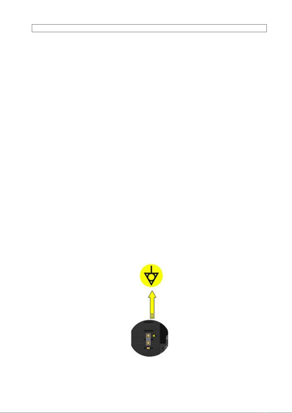
The electrical safety of this machine can be guaranteed only if correctly connected to an efficient earth circuit as indicated by current
electrical safety regulations.
It is necessary to check this fundamental safety prerequisite, and in case of doubt, ask a professionally qualified technician to check
the circuit.
The manufacturer declines all responsibility for any damage caused by failure to earth the equipment.
In order to avoid any dangerous overheating, we recommend that the power cord be fully unwound.
Do not leave the machine connected unnecessarily.
Turn off the machine when not in use.
Place the machine at an adequate distance from walls, objects, etc.
The power cord of this machine must not be replaced by the customer. In case of damage to the cord, contact exclusively an
authorised service centre to have it replaced.

lb-05073-04-EN Pag. 4 30/09/14
TECHNICAL DATA
Model
A01
A02
Width mm. 215 215
Height mm. 584 624
Depth mm. 420 420
Net weight Kg. 22 23
Cold Room capacity
Lt. 11,8
Cold Room data
Gas type R134a
Gas Quantity - g 35
Compressor Name PL35G
Climatic class N
Pressure LP= 2,5 bar / HP= 14bar
Electical data
100-120V @ 50/60Hz
200V @ 50/60Hz
220-240V @ 50/60Hz
Power W. 75
Measured noise dB. <70

lb-05073-04-EN Pag. 5 30/09/14
POTENTIAL – EQUALIZING CONNECTION
ITALIANO
Questo collegamento previsto da alcune normative di sicurezza, ha la funzione di evitare le differenze di livello potenziale
elettrico, tra le masse delle apparecchiature installate nello stesso locale.
Questo apparecchio è predisposto con un morsetto posto sotto il basamento per il collegamento di un conduttore
equipotenziale.
Terminata l’installazione è NECESSARIO eseguire questo tipo di collegamento:
Usare un conduttore elettrico avente una sezione nominale conforme alle norme vigenti.
Collegare un capo del conduttore al morsetto sotto la base dell’ apparecchio e l’altro capo alle masse delle
apparecchature adiacenti.
La mancata attuazione di questa norma di sicurezza scagiona il costruttore da ogni responsabilità per guasti o Danni che
possano essere causati a persone o cose.
NOTA BENE: NON COLLEGARE ALLA MESSA A TERRA DELL’IMPIANTO DI DISTRIBUZIONE ELETTRICA IN QUANTO IL CONDUTTORE
DI MESSA A TERRA IN UN CAVO DI ALIMENTAZIONE NON VIENE CONSIDERATO UN CONDUTTORE DI COLLEGAMENTO
EQUIPOTENZIALE.
ENGLISH
This connection, which is the one called for by several safety norms, avoids electrical potential differences building up between
any equipment that may be installed in the same place.
There is a terminal connector under the device base to which an external potential-equalizing wire should be connected.
This connection is ABSOLUTELY NECESSARY and must be made right after the device is installed.
Use a electric wire whose cross-sectional area conforms to the existing norms.
Make the terminal connection and then connect the other end to the ground connections located on the adjacent
equipment.
Failure to do observe these safety precautions will exempt the manufacturer from any responsibility as regards demage caused
by persons or property.
NOTE: DO NOT CONNECT THE DEVICE’S TERMINAL CLIP TO THE MAINS GROUND TERMINAL BECAUSE THE GROUND TERMINAL
OF ANY MAIN SOURCE OF ELECTRICAL POWER IS NOT CONSIDERED TO BE A POTENTIAL-EQUALIZING CONNECTION.
GERMAN
Dieses Gerät ist unter dem Untergestell mit einer Anschlußklemme versehen, die mit einem externen Stomausgleichsleiter zu
verbinden ist.
Nach der Installation MUSS der Stromanschluß wie folgt vorgenommen:
Einen Leiter verwenden, dessen Nennquerschnitt den einschlägigen Unfallschutzbestimmungen entspricht;
Ihn wie in der Abbildung gezeigt an die Klemme anschließen.
Bei Nichtbeachtung dieses Sicherheitshinweises schließt der Hersteller jedwede Haftungsanprüche für Personen- oder
Sachschäden aus.
HINWEIS: NICHT AN DIE ERDUNG DER STROMZUFUHRANLAGE ANSCHLIESSEN, DA DER ERDUNGSLEITER EINES
SPEISUNGSKABELS NICHT ALS AUSGLEICHSLEITER GELTEN KANN.

lb-05073-04-EN Pag. 6 30/09/14
ASSEMBLY AND ELECTRICAL CONNECTIONS
IMPORTANT
Before carrying out any operation, power OFF the coffee machine, close the water mains and wait the pressure drop.
The below procedure explains how to fit the Fridge A01 Plus to the coffee machine.
Open the front door of the coffee
machine and remove the upper nut
that hold the left side panel.
Remove the left hand side panel.
Remove the pre-cut on the
machine basement by means of a
screwdriver and hammer.
Connect the fridge serial wires to
the connector CN23 (232 slave).
Remove the master board cover.
Let the fridge serial wires go
through the slot.

lb-05073-04-EN Pag. 7 30/09/14
Place back the master board cover.
Insert the inlet milk pipe into the pass
bulkhead, and then trough the side
panel hole.
Place back the left hand side
panel.
Insert the milk inlet pipe into the
fridge side panel hole.
Insert the milk inlet pipe through the
hole in the lid of the milk tank.
Connect the power cord on the
basement fridge socket and the fridge
serial wire to the machine
Place the tank inside the fridge with
the reed milk level as shown in the
picture. The tank must be pushed
until it touches the bottom of the
fridge.
The reed milk level must be
placed in its
seat of the tank with the black top
upward and the base with
sign downward.
Make sure that the serial
cable is fixed as in the photo and
does not come into contact with
the supporting table

lb-05073-04-EN Pag. 8 30/09/14
STARTING UP
1- The fridge can work even if it is not connected to the coffee machine in this case will works with the default
temperature parameters.
2 - In case the fridge is connected to the coffee machine ( transmission cable CN 23 ), it is necessary to enable on
the machine the “FRIDGE” parameter in “MACHINE CONFIGURATION” menu; then set the following parameters in
“MACHINE PARAMETERS”:
- SET-POINT FRIDGE TEMPERATURE : + 4°C / 39,2°F = default value ( variable value : 2 ÷ 15°C / 35,6 ÷ 59°F )
- ALARM FRIDGE TEMPERATURE : + 13°C / 55,4°F = default value (variable value 7 ÷ 30°C / 44,6 ÷ 86°F)
- TIME OUT TEMPERATURE ALARM : 20 min = default value 20 min. ( variable value : 5 ÷120 min.)
- ALARM TEMPERATURE - STOP MILK BASE DRINK : default value = desabled
The coffee machine display will show, “ 67 FRIDGE SERIAL” alarm , that will disappear when the fridge is powered
on.
Power on the fridge by means the main switch underneath the basement.
During the cooling phase the front fridge led will be in green color.
To check the fridge temperature press INFO key on the machine front panel.
GREEN LED
If the fridge need more then 20 minutes to reach the alarm fridge temperature, the front led become in yellow color, in
case the fridge is connected to the coffee machine the display will show also the following message :
46 Fridge temperature
This alarm will disappear as soon the temperature inside the fridge it goes down below the “ALARM FRIDGE
TEMPERATURE” value.
a) We recommend in case you switch off the fridge to wait at least 3 minutes before switching it on again.
b) Only when the milk container is inserted in the fridge, the machine will detect the presence of
milk.
YELLOW LED

lb-05073-04-EN Pag. 9 30/09/14
MILK TANK FILLING
After turning on the fridge unit, wait about 30 minutes to reach a temperature of 4 °C, in case the fridge is connected
to the coffee machine press the INFO key to show the temperature on the coffee machine display, then remove the
tank and fill it with already refrigerated milk.
The maximum capacity of the tank is 4 litres.
Insert the milk inlet pipe through the hole in the lid of the tank.
Place back the milk tank inside the fridge with the reed milk level as shown in the picture.
The tank must be pushed until it touches the bottom of the fridge.
REED MILK LEVEL
a) We recommend in case you switch off the fridge to wait at least 3 minutes before switching it on again.
b) Only when the milk container is inserted in the fridge, the machine will be able to detect the presence of
milk.

lb-05073-04-EN Pag. 10 30/09/14
CLEANING
A - CLEANING THE MILK TUBE SYSTEM:
We recommend to clean the milk tube system at the end of every working day, carrying on the washing cycle
prescribed in the instruction manual of the coffee machine.
B - CLEANING THE MILK TANK:
Wash the milk tank every day using dish detergent and a non-abrasive sponge, then rinse with plenty of water.
In case during the cleaning the reed milk level is removed, must be reinserted in its
seat of the tank with the black top upward and the base with sign downward.
( see the following picture )
C - CLEANING THE INSIDE/OUTSIDE OF THE FRIDGE UNIT:
The inside/outside walls of the fridge unit should be cleaned at the end of every working day, or at least once a week,
with a non-abrasive sponge, soaked with a solution of lukewarm water and neutral detergent.
D- DEFROSTING:
We recommend to defrost the inside of the fridge unit whenever ice on the walls is over 2 mm thick.
This is necessary to guarantee efficient refrigeration and to avoid excessive power consumption.
Please follow this procedure:
- Turn off the power switch of the fridge unit.
- Leave the door open to allow the ice to melt away from the walls.
- Remove the defrosting water from the bottom.
- Clean the inside with a non-abrasive sponge.
- Dry carefully.
Note:
if the door is not tightly closed, ice is formed easily on the walls of the fridge unit.

lb-05073-04-EN Pag. 11 30/09/14
TROUBLE SHOOTING
1) Missing milk alarm
Cause: there is no milk into the container inside the fridge.
Result: the front led become in pink color.
In case the fridge is connected to the coffee machine all milk base drinks are disabled and the
the display will show the following message :
Solution :
- Fill the tank with fresh milk.
- If the alarm is displayed also with the container full of milk, we suggest to check the reed milk level.
2) Milk tank alarm
Cause: the milk tank is not positioned inside the fridge.
Result: the front led become in blu color.
In case the fridge is connected to the coffee machine all milk base drinks are disabled and the
the display will show the following message :
Solution :
- Place the milk tank inside the fridge.
- If the alarm is displayed also with the milk tank positioned inside the fridge, we suggest to check the reed milk
tank.
3) 46 Fridge temperature alarm
Cause: if the fridge need more then 20 minutes to reach the alarm fridge temperature, the front led become in
yellow color.
In case the fridge is connected to the coffee machine the display will show also the following message :
Result: inside the fridge is not possible to reach the set point temperature
Solution:
- This alarm will disappear as soon the temperature inside the fridge it goes down below the “ALARM FRIDGE
TEMPERATURE” value.
- Defrost the fridge
- Check the fridge temperature probe
- Check the fridge pc board
Missing milk
Milk tank
46 Fridge temperature
YELLOW LED
PINK LED
BLU LED

lb-05073-04-EN Pag. 12 30/09/14
4) 67 Fridge serial alarm .
Alarm displayed only in case the fridge is connected to the coffee machine
Cause: no data signal from the fridge to the coffee machine, the display will show the following message :
, the display will show the following message :
Result: all milk base drinks are disabled
Solution:
- Check if the fridge is on
- Check the connection between the fridge and coffee machine
(serial wires - connector cn23 on machine master board).
- Check the fridge pc board
- Check the coffee machine master board
5) 45 Fridge temperature probe alarm .
Alarm displayed only in case the fridge is connected to the coffee machine
Cause: the temperature probe sending the incorrect signals to the fridge pc board, the display will show the following
message :
Result: inside the fridge is not possible to reach the set point temperature.
Solution:
- the temperature probe defective / short circuit
- the temperature probe is disconnected ( CN 1 on fridge pc board )
6) Corrupted data alarm .
Any message on the display,
First case: This alarm appears during machine functioning
Cause: incorrect operating data in machine memory.
Result: machine shutdown.
Solution: carry out the following controls.
1. Switch the fridge OFF and ON again after 5 seconds
2. Verify programming data relevant to the operation that is being carried out. They might be varied and
therefore the machine does not recognise the new data.
3. Carry out “ PRESET FRIDGE CONFIGURATION” procedure.
Second case: software programming values or data incorrect, data inserted by means of P.C. programming
incorrect.
Result: machine shutdown.
Solution:
1) Carry out “PRESET FRIDGE CONFIGURATION” procedure
2) Insert new software by means of P.C.
67 Fridge serial
45 Fridge temp. probe
RED LED
FLASHING GREEN LED

lb-05073-04-EN Pag. 13 30/09/14
PRESET FRIDGE CONFIGURATION
PRESET CONFIGURATION DATA :
Proceed as follows :
- power OFF the fridge by means the main switch.
- move the dip switch N°1 on the board as shown in the following picture :
MOVE THE DIP SWITCH N°1 IN POSITION ON
With this function, the fridge will be configured with the following default setting :
- SET-POINT FRIDGE TEMPERATURE : + 4°C / 39,2°F= default value ( variable value : 2 ÷ 15°C / 35,6 ÷ 59°F)
- ALARM FRIDGE TEMPERATURE : + 13°C / 55,4°F = default value ( variable value : 7 ÷ 30°C / 44,6 ÷ 86°F)
- TIME OUT TEMPERATURE ALARM : 20 min = default value 20 min. ( variable value : 5 ÷120 min.)
- ALARM TEMPERATURE - STOP MILK BASE DRINK : default value = desabled
- power ON the fridge , and after 10 seconds power OFF the fridge and move the dip switch 1 in off position.
POSITION OF THE DIP SWITCH TO CONFIGURE THE FRIDGE V2 WITH REED MILK LEVEL ( STANDARD ) :
Proceed as follows :
power OFF the fridge by means the main switch.
move all dip switches on the board as shown in the following picture
MOVE THE DIP SWITCH N°2 IN POSITION ON
power ON the fridge.
OFF

lb-05073-04-EN Pag. 14 30/09/14

lb-05073-04-EN Pag. 15 30/09/14
LEGEND
1 - Negativo Negative
2 + Positivo Positive
3 AS1 Ventola per Eletronica Fan for Electronic
4 AS2 Ventola per Solubili Soluble Fan
5 C Condensatore Capacitor
6 CMP Compressore Compressor
7 CN …. Connettore Connector
8 DP Deep switch Deep switch
9 EI Encoder pistone Inferiore Encoder Lower piston
10 ES Encoder pistone superiore Encoder Upper piston
11 FA Filtro Antidisturbo Antinoise Filter
12 FO Fast-on Fast-on
13 FU … Fusibile Fuse
14 KL Klicson Klicson
15 L…. Led Led
16 M1 Macinino 1 Grinder 1
17 M2 Macinino 2 Grinder 2
18 MDA Motodosatore A Motor for product A
19 MDB Motodosatore B Motor for product B
20 MES Motore Espulsore Motor Ejector
21 MFA Motofrullatore A Mixer Motor A
22 MFB Motofrullatore B Mixer Motor B
23 MG Motoriduttore Ratiomotor
24 MORSZ
Connettore IEC M/F IEC M/F connector
25 MP Motopompa Motorpump
26 MPI Motore Pistone inferiore Group Lower Motor Piston
27 MPL Microinterruttore Presenza Latte Milk presence microswitch
28 MPS Motore Pistone superiore Group High Motor Piston
29 MSI Microinterruttore Sportello Front Door Microswitch
30 OT Ottiche Gruppo Group Optical
31 P … Ponticello Jumper
32 PL Pompa Latte Milk Pump
33 PTC Elemento riscaldante Gruppo Group Heating Element
34 RBL Reed box latte Milk box reed
35 RCC Resistenza Caldaia Caffè Coffee boiler Heating Elemen
36 RCG Resistenza Gruppo Caffè Coffee Group Heating Element
37 RCV Resistenza Caldaia Vapore Steam Boiler Heating Element
38 RD Reed Decaffeinato Decaf. Reed
39 RF Reed cassetto Fondi Coffee waste reed
40 RLL Reed livello latte Milk level reed
41 RRC Relè Resistenza Caldaia Caffe Relè Coffee Boiler Heater
42 RRV Relè Resistenza Caldaia Vapore Relè Steam Boiler Heater
43 RTL Reed presenza tanica Tank reed
44 RV Reed Vaschetta Drip tray reed
45 RV1 Potenziometro Motore Group Trimmer
46 SCL Sensore livello capacitivo Capacitive level sensor
47 SLB Sonda livello bacinella waste level probe
48 SLC Sonda Livello Caldaia Boiler Level Probe
49 SLS Sonda Sicurezza Safety Probe
50 STCC Sonda Temp. Caldaia Caffe Coffee Boiler Temp. Probe
51 STCF Sonda temperatura cella fridge Coold unit Probe

lb-05073-04-EN Pag. 16 30/09/14
52 STCG Sonda Temp. Gruppo Caffè Coffee Group Temp. Probe
53 STCV Sonda Temp. Caldaia Vapore Steam Boiler Temp. Probe
54 STLV Sonda Temp. Lancia Vapore Steam Wand Temp. Probe
55 TRKC Triak Boiler Caffè Triak Coffee Boiler
56 TRKV Triak Boiler Vapore Triak Steam Boiler
57 TRM Potenziometro Display Display Trimmer
58 TRMT potenziometro temperatura Temperature Trimmer
59 TS Termostato Sicurezza Safety Termoswich
60 Y1.1 Elettrovalvola Aria Milker Air milker solenoid valve
61 Y2,1 Elettrovalvola Vapore Milker Steam Milker solenoid valve
62 Y2,2 Elettrovalvola By-Pass By-pass solenoid valve
63 Y2,3 Elettrovalvola Carico Acqua Water inlet solenoid valve
64 Y2,4 Elettrovalvola Lancia Vapore Steam nozzle solenoid valve
65 Y2,5 Elettrovalvola Lancia Acqua Water nozzle solenoid valve
66 Y2,6 Elettrovalvola Mix Lancia Acqua Mix. Water nozzle solenoid valve
67 Y2,7 Elettrovalvola Gruppo Caffe Coffee group solenoid valve
68 Y2,8 Elettrovalvola Risciacquo Milker Milker rinse solenoid valve
69 Y2,9 Elettrovalvola mix acqua fredda gruppo Mix group cold water solenoid valve
70 Y2.10 Elettovalvola Mixer 1 Mixer 1 Solenoid valve
71 Y2.11 Elettovalvola Mixer 2 Mixer 2 Solenoid valve
72 Y2.12 Elettrovalvola Air Break Air Break solenoid valve

lb-05073-04-EN Pag. 17 30/09/14

lb-05073-04-EN Pag. 18 30/09/14
MACHINE MODEL: FRIDGE A01 PLUS NT-05246-02
POS.
FRIDGE
PLUS A01
FRIDGE
PLUS A02
DESCRIZIONE CODICE
1
BASAMENTO MACCHINA HOT & COLD 37.00864
2
PIEDINO H.45 37.00455.L1
2
PIEDINO H.22 37.00456.L1
2
PIEDINO H.77 37.00411.L1
3
● MANTELLO BIANCO FRIDGE A01 11.02246.V19
3
● MANTELLO INOX FRIDGE A01 14.02706
3
■ MANTELLO BIANCO FRIDGE A02 11.05056.V19
3
■ MANTELLO INOX FRIDGE A02 14.05028
4
INTERRUTORE BIPOLARE 96.00905
5
VITE TC CROSS ZN M 4X30 91.00066
6
SPINA A SCATTO X CAVO IEC 10A 96.00872
7
CAVO ALIM. IEC SCHUKO 10A 250V 2 MT 96.00612
8
VITE TC CROSS ZN M 4X30 91.00066
9
VITE TCEI M 4X12 91.00278
10
VITE TCEI M 4X12 91.00095
11
SUPPORTO CELLA FRIDGE PLUS A01/A02 V2 11.05218
12
ASS. BACINELLA LATTE + COPERCHIO 01.02323
13
COPERCHIO BACINELLA LATTE 37.00758
14
GALLEGGIANTE BACINELLA LATTE 37.05081
15
SOTTO TAPPO PLASTICA Ø28 95.01940
16
SQUADRETTA FIX COPERTURA FRONTALE FRIDGE PLUS V2 11.05257
17
● COPERTURA FRONTALE FRIDGE A01 (V2) 14.05098
17
■ COPERTURA FRONTALE FRIDGE A02 (V2) 14.05125
18
VITE INOX TE M 4X6 91.00186
19
LOGO MACCO RESINATO ADESIVO PICCOLO 33.05045
19
LOGO CARIMALI RESINATO ADESIVO PICCOLO 33.05043
20
BASE PER LOGO PICCOLO Ø51,5 37.05061.CR
21
DIFFUSORE LED RGB FRIDGE PLUS A01/A02 V2 95.05128
22
LED SINGOLO RGB FRIDGE A01/02 PLUS (2) 96.05036.L3
23
COLONNINA M4 FF H14 CH7 22.01247
24
DISTANZIALE CENTRALINA M3 X 10 37.00430
25
SCHEDA CONTROLLO 230V FRIDGE A01/02 PLUS 96.05039
26
VITE TC + ROSETTA M 3X6 91.00263
27
SUPPORTO SCHEDA/TRAFO FRIDGE A01 PLUS 11.05087
28
RIPIANO SUPERIORE (2) FRIDGE A01 14.05044
29
VITE SPEC. TC CROSS M4X8 14.00454
30
BOCCOLA ARMONIA UR 12.00049
31
CELLA FRIGORIFERA 230V FRIDGE PLUS V2 96.05110
32
RACC. PASSAPARATIA FRIDGE A01/02 37.05084
33
VITE INOX TS CROCE M 6X40 91.05014
34
DISCO Ø95 GOMMA X TRAFO TOROIDALE FRIDGE PLUS 95.05068
35
TRAFO TOR. T180.S.010 1X200 1X225 180VA 50/60HZ 96.05075.CA.45
36
DISCO Ø60 GOMMA X TRAFO TOROIDALE FRIDGE PLUS 95.05065
37
PIATTELLO FISSAGGIO TRAFO TOROIDALE FRIDGE PLUS 95.05064
38
DADO INOX M 6 92.00046
39
VITE INOX TE + ROSETTE M 4X12 91.05012
40
CARTER PROTEZIONE SONDA TEMP.FRIDGE A01/02 PLUS V2 14.05100
41
FERMACAVO AUTOADESIVO X SONDA TEMPERATURA 95.05051
42
SONDA DI TEMPERATURA FRIDGE A01/02 PLUS 96.05042.CA
43
SENSORE BACINELLA LATTE FRIDGE PLUS 96.05076.L1
44
SENSORE LIVELLO LATTE FRIDGE PLUS 96.05076.L2
45
CABL. TRASMISSIONE FRIDGE A01 PLUS (LATO FRIDGE) 03.05055

lb-05073-04-EN Pag. 19 30/09/14
46
CABL. TRASMISSIONE FRIDGE A01 PLUS (LATO MACCHINA) 03.05047
47
GUARNIZIONE SPORTELLO CELLA FRIGORIFERA PLASTICA (2) 95.05144
48
VENTILATORE 230V CELLA FRIGORIFERA V2 96.05210
49
SPORTELLO CELLA FRIGORIFERA V2 95.05145
50
PERNO CERNIERA SPORTELLO FRIDGE PLUS V2 A01/A02 16.05081
51
CONDENSATORE 60uF 96.05264.CA

lb-05073-04-EN Pag. 20 30/09/14
The Carimali product you have purchased is subject to Directive 2002/96/EC of the European Parliament
and the Council of the European Union on waste electrical and electronic equipment (WEEE) and, in
jurisdictions adopting that Directive, is marked as being put on the market after August 13, 2005, and
should not be disposed of as unsorted municipal waste. For further information please contact Carimali
The manufacturer reserves the right to change, without prior notice, the specifications of the equipment
illustrated in this publication; the manufacturer declines all responsibility for any mistakes due to printing
and/or typing errors contained in this publication.
All instructions, drawings, tables and information contained in this publication are reserved and may not
be reproduced entirely or in part or be communicated to a third party without written authorisation from
the manufacturer who holds exclusive rights.
Tabella Revisioni DATE NOTE Revisionato da:
LB-05073.00 02/08/2013 1° Edizione Lorenzo Cauli
LB-05073.01 09/01/2014 Agg. esplosi Riccardo Rossi
LB-05073.02 22/05/2014 Agg. esplosi Riccardo Rossi
LB-05073.03 06/08/2014
Agg. schema elettrico
Riccardo Rossi
LB-05073.04 29/09/2014
Agg. esploso
Giuliano Viola
The manager
Maurizio Boffelli
Firma del Responsabile della Documentazione
This manual suits for next models
1
Table of contents
Popular Refrigerator manuals by other brands

Haier
Haier HNSE025 Energy guide

Maytag
Maytag MSD2656KES - 26 cu. Ft. Refrigerator Use and care guide

Miele
Miele KFN 14943 SD ed Operating and installation instructions

GE
GE GSL25XGWSS Owner's manual and installation

Currys Essentials
Currys Essentials CUR50W12 instruction manual

Haier
Haier QNE27J Installation and user manual