7
12 PIPING (continued)
Combustion air outdoor termination:
Use PVC elbow
7facing downward
and air intake screen provided
8. Maintain 12"
clearance above highest anticipated snow level.
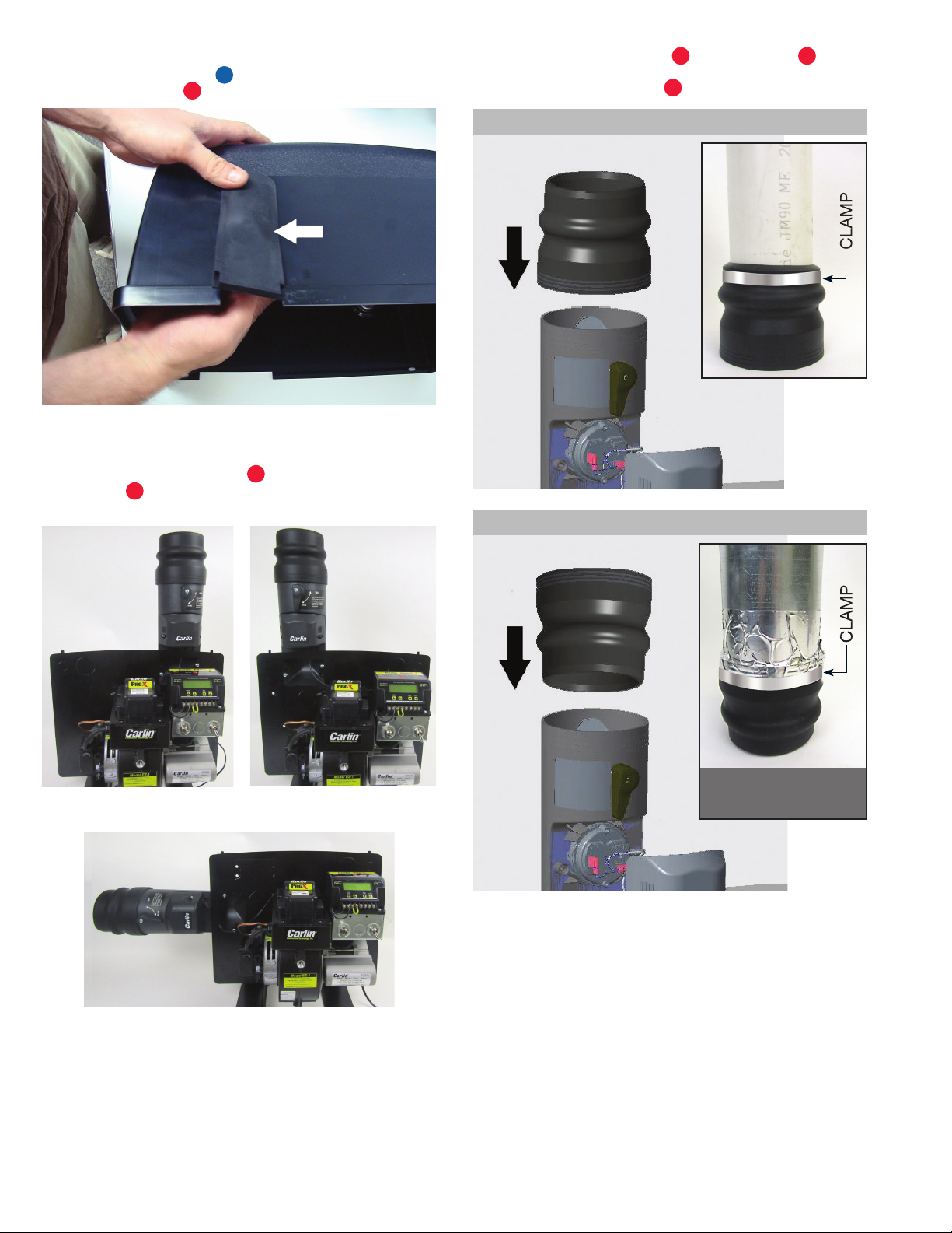
Galvanized
IMPORTANT: For proper operation of the CAP System
galvanized pipe must be sealed air tight (including all
joints and seams) with hi-temp foil tape or mastic stress
tape.
When using galvanized, the CAP system connect-
ing flange 11 needs to be reversed (groove stripes/
wider opening on top). Galvanized should be fitted
inside wider opening until it hits stop/lip (may require
lubricant). Thinner end should be inserted into air inlet
opening 10 . There will be a smaller gap between edge
of connector and galvanized pipe. Tight seal is made
inside connector.
Termination hood (not provided) is needed for use with
galvanized pipe. Maintain 12" clearance above highest
anticipated snow level.
WARNING: Be sure to adhere to manufacturer’s
recommendations and all local codes with regards
to proximity of combustion air piping to appliance
vent/exhaust stack.
Avoid locations where snow may drift and block
combustion air. Ice or snow may cause boiler to
shut down if combustion air becomes obstructed.
Combustion air termination must be min. 12" from
or below doors, windows or gravity inlet. USE
SWEEP ELBOWS FOR ALL COMBUSTION AIR
PIPING. DO NOT USE short radius elbows for com-
bustion air piping – boiler performance could be
affected.
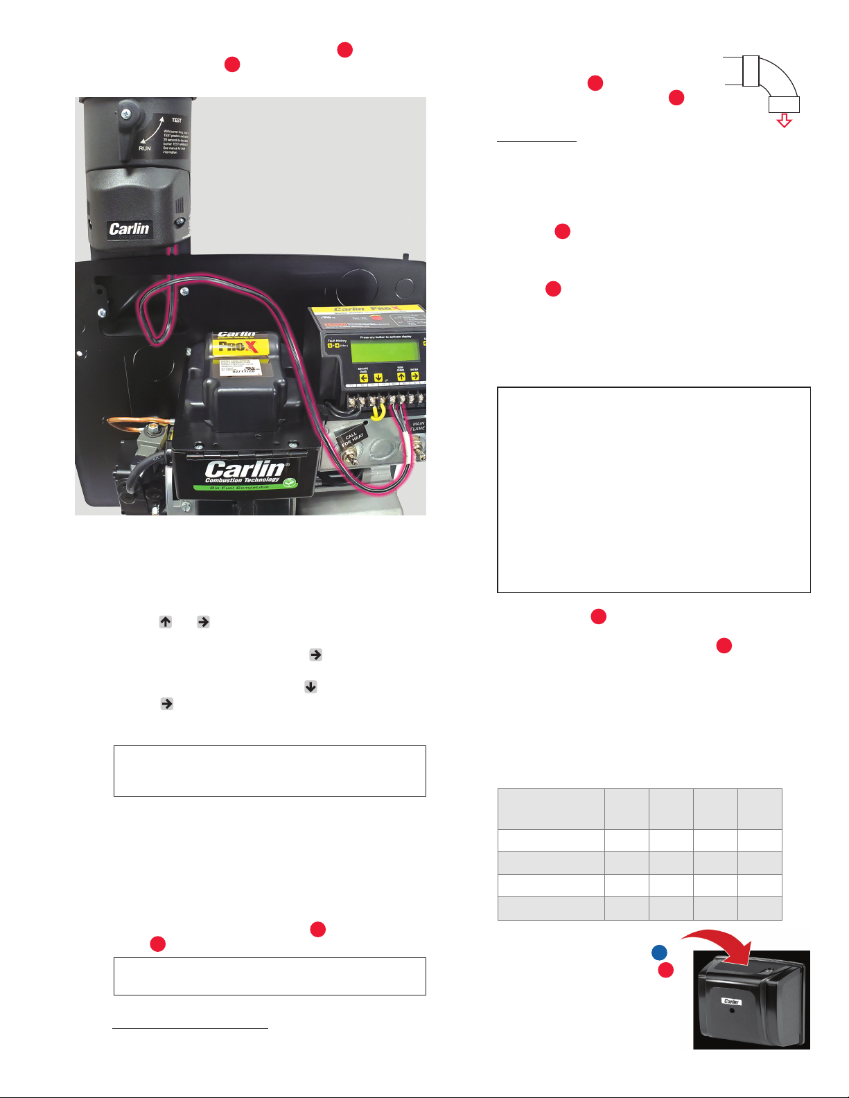
13 Mount the cover
1by aligning the two holes on the
top flange of the cover with the mounting tabs on the
backplate. Tighten the mounting screw 1b , located in
the center of the cover, securely to prevent basement air
from entering the cover.
14 CHECK BURNER SETUP
CAP System utilizes outside air for combustion.
Incoming air temperature will fluctuate by season
which can significantly impact combustion. Use the
table below to set the combustion settings based on
outside temperatures at the time of setup.
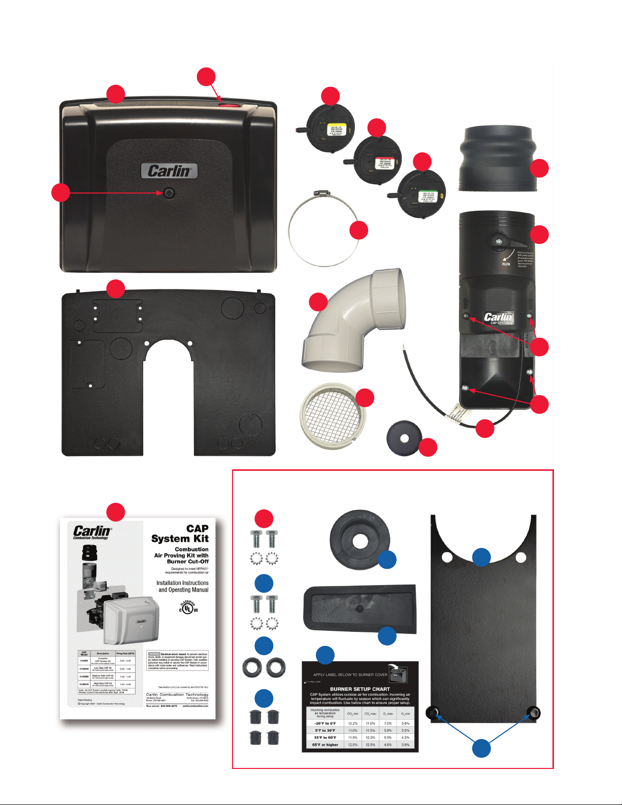
• Apply the burner setup label 20
to the top of the burner cover
1.
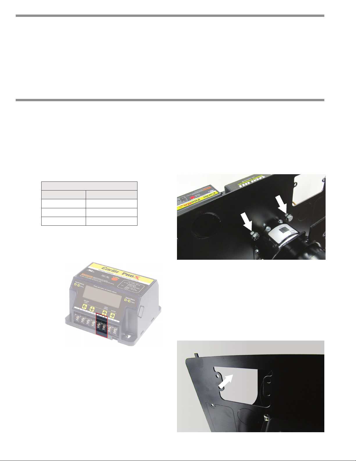
10 Route the Air Flow Switch Wire Harness 10a from the
combustion air inlet 10 to the low voltage blocked vent
(BV) contacts on the Pro-X 70200 primary control.
11 SETTING BLOCKED VENT + AIR INTAKE FEATURE
The Pro-X 70200 Primary Control (manufactured
Sept. 2018 or later) is equipped with a Blocked Vent
Air Intake feature that works in conjuction with the CAP
System. To activate this setting:
• Press and simultaneously for 2 seconds. This
brings you to the settings menu.
• Scroll through the settings using until you reach
Vent Input.
• Scroll down to Intake using the .
• Press / ENTER button. The display will briefly indi-
cate Vent Input has been “Entered” and has replaced
any previous setting.
NOTE: If the Pro-X 70200 is also connected to a
blocked exhaust switch, call Carlin Technical Support
for assistance.
12 PIPING
3" PVC (recommended) or 4" galvanized vent pipe must
be installed to provide outside air to the CAP System.
(Maximum run of 80 total feet with each elbow equaling
10 feet. Example: 40 feet straight pipe and 4 elbows =
80 feet total run.)
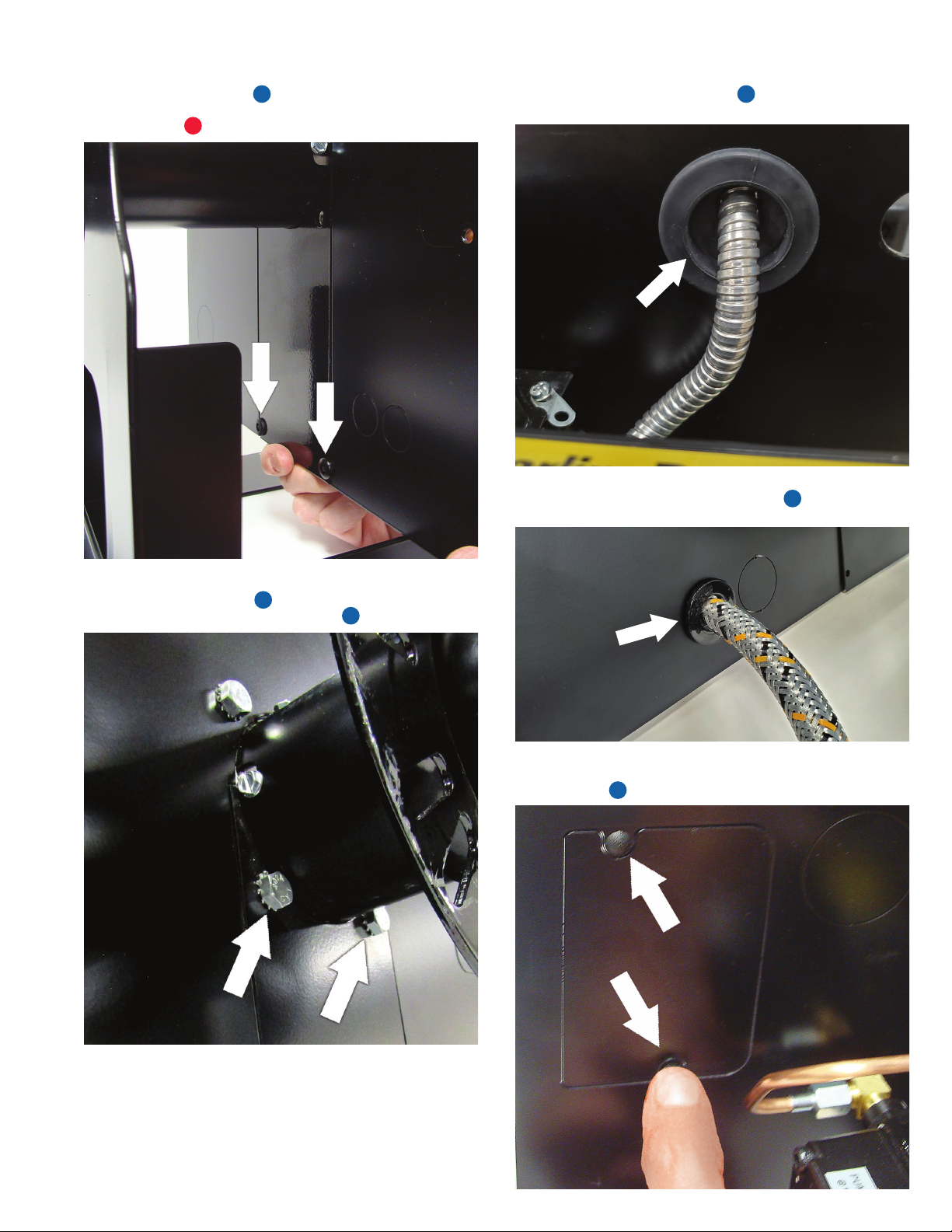
Secure piping to connecting flange 11 using
clamp
6. (See step 9.)
NOTE: Galvanized pipe should not be used with firing
rate less than 0.65 GPH.
Important PVC Specs
For proper operation of the CAP System, air inlet piping
should only use schedule 40 or 80 PVC.
Incoming combustion
air temperature
during setup CO2min CO2max O2max O2min
–20°F to 0°F 10.2% 11.0% 7.0% 5.8%
5°F to 30°F 11.0% 11.5% 5.8% 5.5%
35°F to 60°F 11.5% 12.2% 5.5% 4.2%
65°F or higher 12.0% 12.5% 4.6% 3.9%