RAV-180-01SI Specifications subject to change without notice. 7
CURB-MOUNTED INSTALLATION
1. Install curb
2. Install field-fabricated ductwork inside curb
3. Install accessory thru-base service connection pack-
age (affects curb and unit) (refer to accessory instal-
lation instructions for details)
4. Prepare bottom condensate drain connection to suit
planned condensate line routing (see Install External
Condensate Trap and Line on page 11 for details)
5. Rig and place unit
6. Install outdoor air hood
7. Install condensate line trap and piping
8. Make electrical connections
9. Install other accessories
PAD-MOUNTED INSTALLATION
1. Prepare pad and unit supports
2. Check and tighten the bottom condensate drain con-
nection plug
3. Rig and place unit
4. Convert unit to side duct connection arrangement
5. Install field-fabricated ductwork at unit duct openings
6. Install outdoor air hood
7. Install condensate line trap and piping
8. Make electrical connections
9. Install other accessories
FRAME-MOUNTED INSTALLATION
Frame-mounted applications generally follow the sequence
for a curb installation. Adapt as required to suit specific in-
stallation plan.
Step 3 — Inspect Unit
Inspect unit for transportation damage. File any claim with
transportation agency. Confirm before installation of unit that
voltage, amperage and circuit protection requirements listed
on unit data plate agree with power supply provided.
Step 4 — Provide Unit Support
ROOF CURB MOUNT
Accessory roof curb details and dimensions are shown in
Fig. 5. Assemble and install accessory roof curb in
accordance with instructions shipped with the curb. Curb
should be level. This is necessary for unit drain to func-
tion properly. Unit leveling tolerances are shown in Fig. 4.
Refer to Accessory Roof Curb Installation Instructions for
additional information as required.
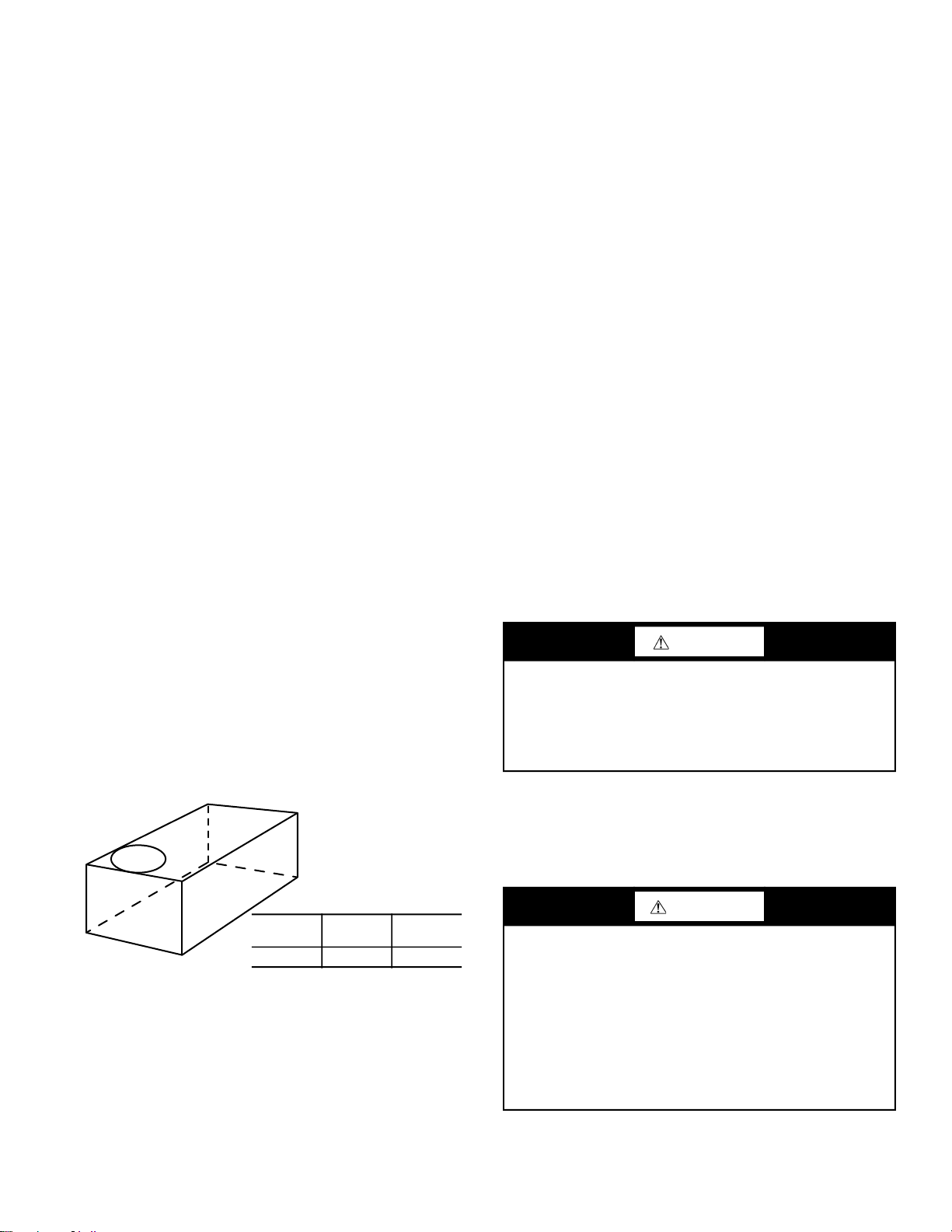
Fig. 4 — Unit Leveling Tolerances
NOTE: The gasketing of the unit to the roof curb is critical
for a watertight seal. Install gasket supplied with the roof
curb as shown in Fig. 5. Improperly applied gasket can also
result in air leaks and poor unit performance.
Install insulation, cant strips, roofing felt, and counter flash-
ing as shown. Ductwork must be attached to curb and not to
the unit.
SLAB MOUNT (HORIZONTAL UNITS ONLY)
Provide a level concrete slab that extends a minimum of
6 in. (150 mm) beyond unit cabinet. Install a gravel apron in
front of condenser coil air inlet to prevent grass and foliage
from obstructing airflow.
NOTE: Horizontal units may be installed on a roof curb if
required.
ALTERNATE UNIT SUPPORT (IN LIEU OF CURB OR
SLAB MOUNT)
A non-combustible sleeper rail can be used in the unit curb
support area. If sleeper rails cannot be used, support the
long sides of the unit with a minimum of 3 equally spaced
4 in. x 4 in. (102 mm x 102 mm) pads on each side.
Step 5 — Field Fabricate Ductwork
NOTE: Cabinet return-air static pressure (a negative condi-
tion) shall not exceed 0.35 in. wg (87 Pa) with economizer
or 0.45 in. wg (112 Pa) without economizer.
For vertical ducted applications, secure all ducts to roof curb
and building structure. Do not connect ductwork to unit.
Fabricate supply ductwork so that the cross sectional di-
mensions are equal to or greater than the unit supply duct
opening dimensions for the first 18 in. (458 mm) of duct
length from the unit basepan.
Insulate and weatherproof all external ductwork, joints, and
roof openings with counter flashing and mastic in accor-
dance with applicable codes.
Ducts passing through unconditioned spaces must be insu-
lated and covered with a vapor barrier.
If a plenum return is used on a vertical unit, the return
should be ducted through the roof deck to comply with ap-
plicable fire codes.
A minimum clearance is not required around ductwork.
FOR UNITS WITH ACCESSORY ELECTRIC HEATERS
All installations require a minimum clearance to combustible
surfaces of 1 in. (25 mm) from duct for first 12 in. (305 mm)
away from unit.
Outlet grilles must not lie directly below unit discharge.
A-B
IN. (MM)
B-C
IN. (MM)
A-C
IN. (MM)
0.5 (13) 1.0 (25) 1.0 (25)
CAUTION
PROPERTY DAMAGE HAZARD
Failure to follow this caution may result in damage to
roofing materials.
Membrane roofs can be cut by sharp sheet metal edges.
Be careful when placing any sheet metal parts on such
roof.
WARNING
PERSONAL INJURY HAZARD
Failure to follow this warning could cause
personal injury.
For vertical supply and return units, tools or parts could
drop into ductwork and cause an injury. Install a
90 degree turn in the return ductwork between the unit
and the conditioned space. If a 90 degree elbow cannot
be installed, then a grille of sufficient strength and
density should be installed to prevent objects from falling
into the conditioned space. Due to electric heater, supply
duct will require 90 degree elbow.


 null")