Introduction
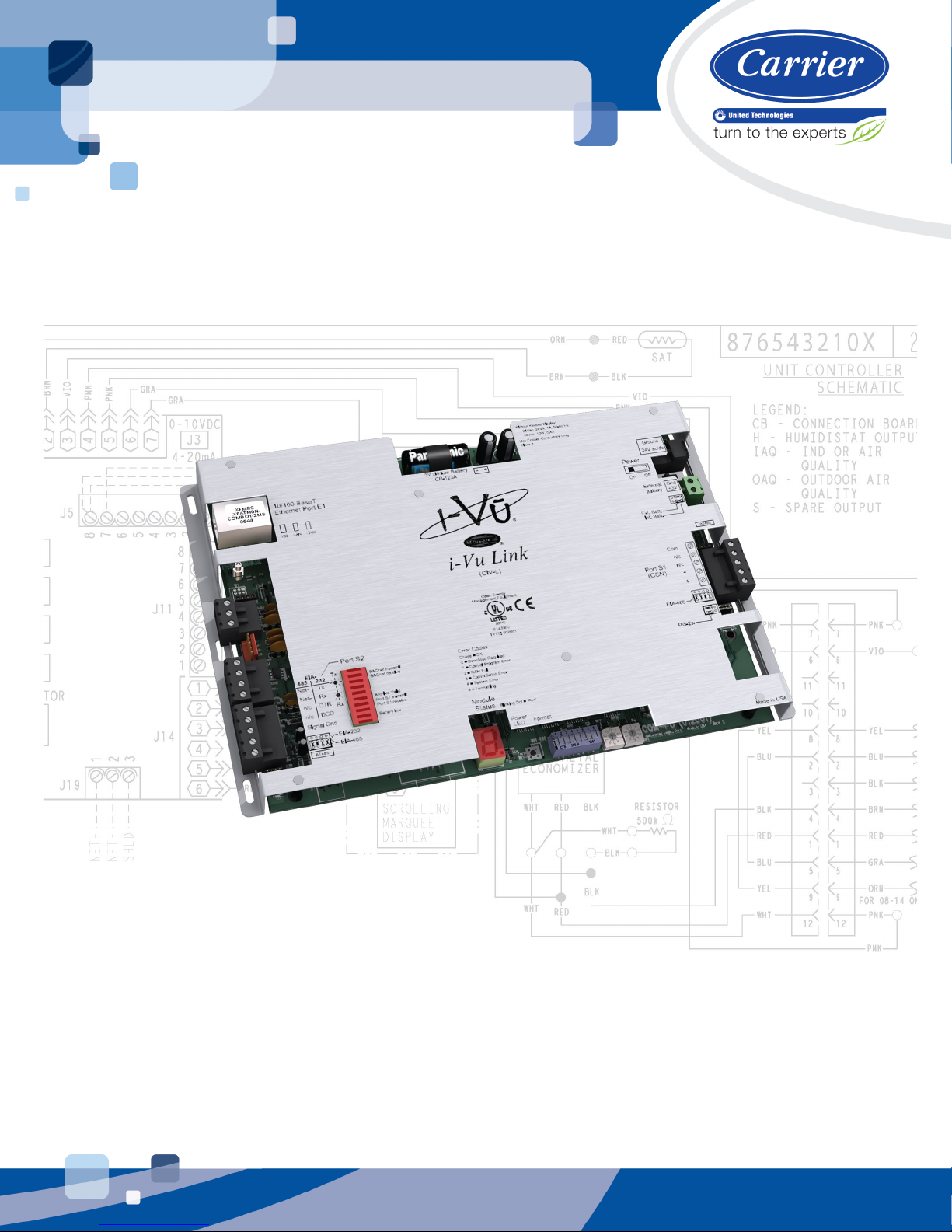
i-Vu® Link CARRIER CORPORATION ©2019
Installation Guide All rights reserved
2
Module drivers drv_ivulink_modbus
drv_ivulink_lon
Maximum number of CCN
controllers
140
Maximum number of third
party points
500
Power 24 Vac ±10%, 50–60 Hz, 24 VA
26 Vdc ±10%, 10 W
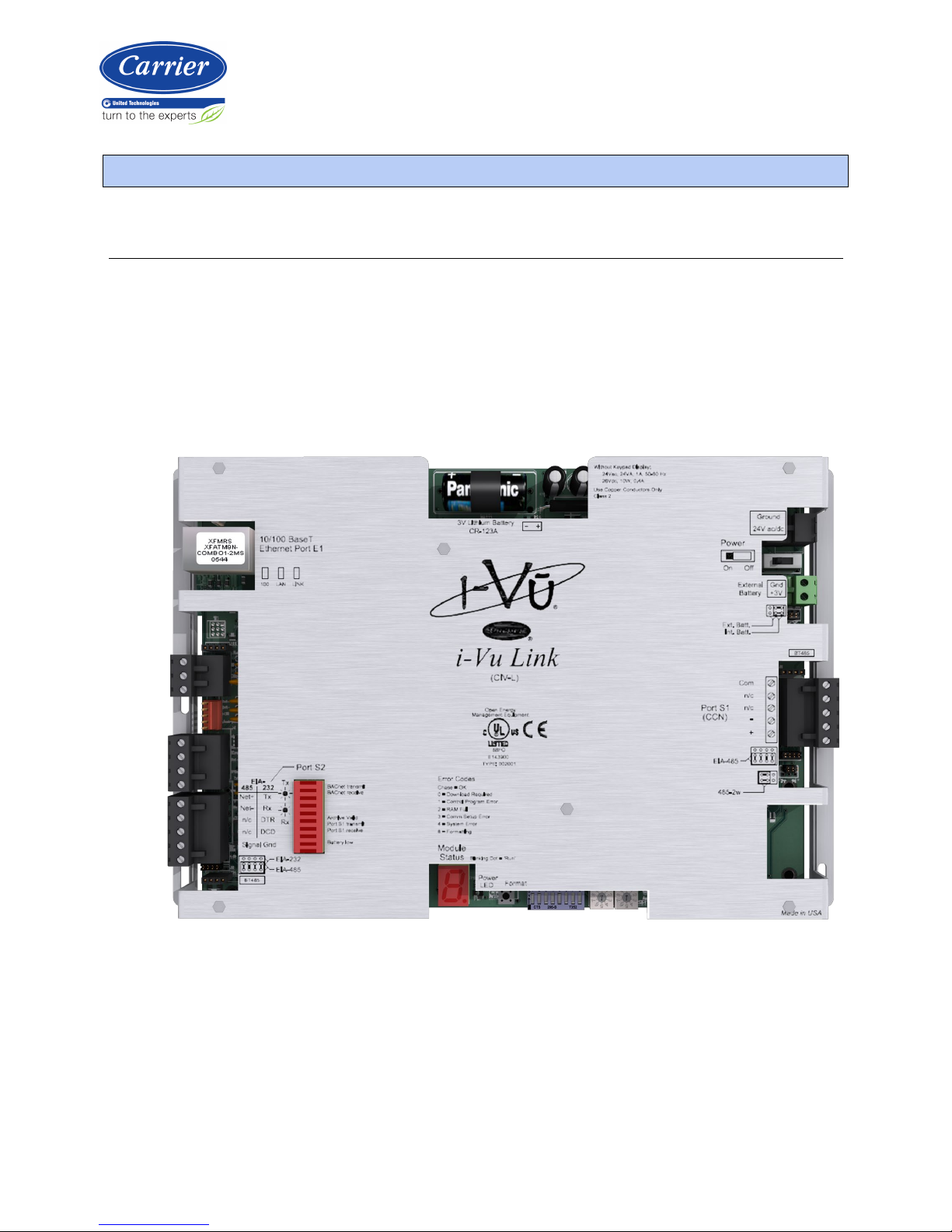
Communication ports 10/100 BaseT Ethernet
: LAN, BACnet IP, and/or Modbus TCP/IP
communications
: 5-pin EIA-485 for CCN Network and/or CCN Service Tool connection
(9600 and 38400 baud)
: Configurable EIA-485/EIA-232 for third party network connections,
including:
•BACnet MS/TP @ 9600, 19200, 38400, and 76800 baud
•Modbus (RTU and ASCII modes) @ 9600, 19200, 38400, and 76800 baud
•LonWorks (requires SLTA-10 adapter) @ 38400 and 76800 baud
Microprocessor 32-bit Motorola Power PC microprocessor with cache memory, Fast Ethernet
controller, high performance 32-bit communication co-processor
Memory 16 MB non-volatile battery-backed RAM (with 12 MB available for use), 8 MB
Flash memory, 32-bit memory bus
NOTE Shelf life of battery is 10 years with 720 hours of continuous operation.
Battery 10-year Lithium CR123A battery ensures the following data is retained for a
maximum of 720 hours during power outages:
•Time
•Graphics
•Control programs
•Editable properties
•Schedules
•Trends
To conserve battery life, you can set the driver to turn off battery backup after a
specified number of days and depend on the archive function to restore data
when the power returns.
A low battery is indicated by the
LED or a low battery alarm in the i-
Vu CCN Plus/Pro application, a touchscreen device, and Field Assistant.
Real-time clock Battery-backed real-time clock keeps track of time in event of power failure