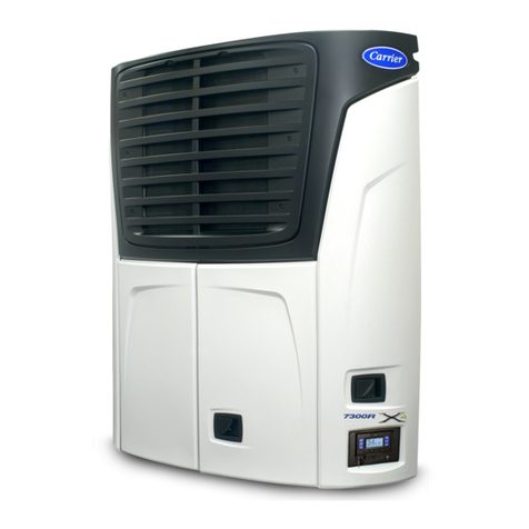
Carrier VECTOR 1800 MT Installation and operating instructions


OPERATION & SERVICE
MANUAL
for
VECTOR 1800 MT
Trailer
Multi--Temp
Refrigeration Units

i62--11039
TABLE OF CONTENTS
PARAGRAPH NUMBER Page
SAFETY PRECAUTIONS 1-1.....................................................................
1.1 SAFETY PRECAUTIONS 1-1.............................................................
1.2 SPECIFIC WARNING AND CAUTION STATEMENTS 1-1.....................................
1.3 SAFETY DECALS 1-5....................................................................
UNIT DESCRIPTION 2-1..........................................................................
2.1 INTRODUCTION 2-1.....................................................................
2.2 GENERAL DESCRIPTION 2-2.............................................................
2.3 CONDENSING SECTION 2-7.............................................................
2.3.1 Condenser Coil 2-7...................................................................
2.3.2 Engine 2-7...........................................................................
2.3.3 Compressor 2-7......................................................................
2.3.4 Filter Drier 2-9........................................................................
2.3.5 Receiver 2-9.........................................................................
2.3.6 Transducers and Sensors 2-10..........................................................
2.4 COMPARTMENT 1 EVAPORATOR SECTION 2-10............................................
2.4.1 Electronic Expansion Valve (EVXV) 2-10..................................................
2.4.2 Heat Exchanger 2-10...................................................................
2.4.3 Evaporator Coil 2-10...................................................................
2.4.4 Transducers and Sensors 2-10..........................................................
2.5 REMOTE EVAPORATOR(S) 2-11...........................................................
2.6 SYSTEM OPERATING CONTROLS AND COMPONENTS 2-11.................................
2.6.1 Multiple Languages 2-11................................................................
2.6.2 Special Features 2-11..................................................................
2.6.3 Microprocessor Component Description And Location 2-12..................................
2.7 ELECTRONIC MODULES 2-18.............................................................
2.7.1 Overload Ground Fault Module (OGF) 2-18...............................................
2.7.2 Phase Reversal Module (PRM) 2-18.....................................................
2.8.1 Light Bar 2-18.........................................................................
2.8.2 Door Switch(es) 2-18...................................................................
2.8.3 Out of Range Alarm 2-19...............................................................
2.8.4 Remote Control Panel 2-19.............................................................
2.9 ENGINE DATA 2-20.......................................................................
2.10 ENGINE AIR SYSTEM 2-20................................................................
2.11 COMPRESSOR DATA 2-21................................................................
2.12 REFRIGERATION SYSTEM DATA 2-21......................................................
2.13 ELECTRICAL DATA 2-22...................................................................
2.14 COMPONENT RESISTANCE & CURRENT DRAW 2-23.......................................
2.15 SAFETY DEVICES 2-23...................................................................
2.16 REFRIGERANT CIRCUIT DURING COOLING 2-24...........................................
2.17 REFRIGERANT CIRCUIT -- HEATING AND DEFROSTING 2-24................................

ii
62--11039
TABLE OF CONTENTS (Continued)
PARAGRAPH NUMBER Page
OPERATION 3-1.................................................................................
3.1 RS “ON” AND ALL COMPARTMENT SWITCHES “OFF” 3-1...................................
3.2 STARTING UNIT -- ENGINE/ROAD OPERATION 3-2.........................................
3.3 STARTING UNIT -- ELECTRIC STANDBY OPERATION 3-3...................................
3.4 UNIT STARTUP -- ENGINE/ROAD AND ELECTRIC STANDBY 3-5.............................
3.5 PRETRIP 3-6............................................................................
3.6 CHANGING SETPOINT 3-9...............................................................
3.7 START--STOP OPERATION -- ENGINE/ROAD AND ELECTRIC STANDBY 3-10..................
3.8 CONTINUOUS RUN OPERATION 3-11......................................................
3.9 SLEEP MODE ON/OFF 3-12...............................................................
3.10 MANUAL DEFROST 3-14..................................................................
3.11 TRIP START 3-15.........................................................................
3.12 VIEW ACTIVE ALARMS 3-16...............................................................
3.13 VIEW INACTIVE ALARMS 3-17.............................................................
3.14 UNIT DATA 3-18..........................................................................
3.15 VIEW HOURMETERS 3-22.................................................................
3.16 FUNCTIONAL CHANGE (PARAMETERS) 3-23...............................................
3.17 LANGUAGE SELECTION 3-27.............................................................
3.18 STOPPING UNIT 3-28.....................................................................
3.19 DATA RECORDING 3-29...................................................................
3.19.1 Microprocessor Information 3-29.........................................................
3.19.2 Data Recording 3-29...................................................................
3.19.3 Sensor & Event Data 3-29..............................................................
3.19.4 Data Downloading 3-30.................................................................
3.19.5 Data Recorder Power--Up 3-30..........................................................
3.20 OPTIONS 3-31...........................................................................
3.20.1 IntelliSet 3-31.........................................................................
3.20.2 Remote Control Panel 3-34.............................................................
TEMPERATURE CONTROL 4-1...................................................................
4.1 SYSTEM START--UP 4-1.................................................................
4.2 START--STOP OPERATION 4-2...........................................................
4.3 CONTINUOUS RUN OPERATION 4-4......................................................
4.4 TEMPERATURE CONTROL 4-4...........................................................
4.4.1 COOL MODE 4-4........................................................................
4.4.2 PULSE COOL MODE 4-5.................................................................
4.4.3 PRIORITY MODES 4-5...................................................................
4.4.4 SUPPLY AIR LIMIT CONTROL 4-5.........................................................
4.4.5 HEAT MODE 4-6.........................................................................
4.4.6 NULL MODE 4-6.........................................................................
4.4.7 UNLOADERS 4-6........................................................................
4.4.8 SPEED CONTROL 4-7...................................................................
4.4.9 DEFAULT MODE 4-7.....................................................................
4.4.10 DEFROST OPERATION 4-7...........................................................

iii 62--11039
TABLE OF CONTENTS (Continued)
PARAGRAPH NUMBER Page
4.5 Temperature Range Lock 1 & 2 4-9.........................................................
4.6 ProductShieldt 4-11........................................................................
4.6.1 Modes 4-11............................................................................
4.6.2 Temperature Ranges 4-12................................................................
4.7 OUTPUT OVERRIDES 4-15................................................................
4.7.1 Speed Control Solenoid (SCS) Overrides 4-15.............................................
4.7.2 Unloader Control Overrides 4-16.........................................................
4.7.3 Suction Pressure Operation 4-18........................................................
TECHNICIAN INTERFACE 5-1.....................................................................
5.1 PC MODE/DOWNLOAD PORT 5-1.........................................................
5.2 MICROPROCESSOR CONFIGURATION AND TECHNICIAN TEST MODES 5-2.................
5.2.1 Configuration Mode 5-3................................................................
5.2.2 Component Test Mode 5-12.............................................................
5.2.3 Service Mode 5-14.....................................................................
5.3 DOWNLOADING DATA WITH THE PC CARD 5-15............................................
5.4 INSTALLING NEW SOFTWARE 5-16........................................................
5.4.1 Using The Program PC Card 5-16.......................................................
5.4.2 Using MicroProgrammer 5-17...........................................................
5.4.3 Troubleshooting Software Loading Problems 5-17..........................................
5.5 SETTING PM (PREVENTATIVE MAINTENANCE) HOURMETERS 5-18.........................
5.6 ADVANCE MICROPROCESSOR REPLACEMENT & CONFIGURATION SETUP 5-19.............
5.6.1 Microprocessor Replacement 5-19.......................................................
5.6.2 Microprocessor Setup 5-20..............................................................
5.6.3 Configurations Via Keypad 5-20.........................................................
5.6.4 Functional Parameters Via Keypad 5-21..................................................
5.6.5 DataRecorder Via ReeferManager PC Program 5-21.......................................
5.6.6 Engine And Switch--on Hour Meters Via ReeferManager PC Program 5-21....................
5.6.7 Configuration/IntelliSet Card 5-22........................................................
5.6.8 Microprocessor Final Checkout 5-22.....................................................
MESSAGECENTER 6-1...........................................................................
6.1 MessageCenter Messages 6-1.............................................................
ALARM TROUBLESHOOTING 7-1.................................................................
7.1 INTRODUCTION TO ALARM TROUBLESHOOTING 7-1......................................
7.2 NOTES 7-2...............................................................................
7.3 DRIVER/OPERATOR ALARMS 7-3..........................................................
1 LOW FUEL LEVEL WARNING 7-3.........................................................
2 LOW ENGINE OIL LEVEL 7-4.............................................................
3 LOW COOLANT LEVEL 7-5...............................................................

iv
62--11039
TABLE OF CONTENTS (Continued)
PARAGRAPH NUMBER Page
7.4 SHUTDOWN ALARMS 7-6.................................................................
11 LOW ENGINE OIL PRESSURE 7-6........................................................
12 HIGH COOLANT TEMPERATURE 7-7......................................................
13 HIGH DISCHARGE PRESSURE (ALARM 75 WILL ACTIVATE) 7-8.............................
14 ELECTRICAL CIRCUIT 7-9...............................................................
15 BATTERY VOLTAGE TOO HIGH 7-10.......................................................
16 BATTERY VOLTAGE TOO LOW 7-10........................................................
17 HIGH COMP DISCHARGE TEMP 7-11......................................................
18 LOW REFRIGERANT PRESSURE 7-12.....................................................
19 LOW FUEL SHUTDOWN. 7-13.............................................................
20 MAXIMUM COMPRESSOR ALARMS 7-13...................................................
22 LOW SUCTION SUPERHEAT 7-14..........................................................
23 A/C CURRENT OVER LIMIT 7-15...........................................................
27 HIGH SUCTION PRESSURE 7-18..........................................................
28 CHECK REFRIGERATION SYSTEM 7-19....................................................
7.5 START UP/ENGINE ALARMS 7-20...........................................................
30 FAILED TO RUN MINIMUM TIME 7-20......................................................
31 FAILED TO START -- AUTO MODE 7-21.....................................................
34 ENGINE FAILED TO STOP 7-22............................................................
35 CHECK STARTER CIRCUIT 7-23...........................................................
36 CHECK COOLANT TEMPERATURE 7-24....................................................
37 CHECK LOW SPEED RPM 7-25............................................................
38 CHECK HIGH SPEED RPM 7-26............................................................
39 CHECK ENGINE RPM 7-27................................................................
40 CHECK GLOW PLUGS 7-28...............................................................
41 ENGINE STALLED 7-29...................................................................
41 ENGINE STALLED (Continued) 7-30.........................................................
7.6 WARNING / STATUS ALARMS 7-31..........................................................
51 ALTERNATOR NOT CHARGING 7-31.......................................................
53 BOX TEMP OUT--OF--RANGE 7-32.........................................................
54 DEFROST NOT COMPLETE 7-33..........................................................
55 CHECK DEFROST AIR SWITCH 7-34.......................................................
59 DATALOGGER NOT RECORDING 7-35.....................................................
60 DATALOGGER TIME WRONG 7-35.........................................................
62 C2 BOX TEMP OUT--OF--RANGE 7-36......................................................
63 C3 BOX TEMP OUT--OF--RANGE 7-37......................................................

v62--11039
TABLE OF CONTENTS (Continued)
PARAGRAPH NUMBER Page
7.7 ELECTRICAL ALARMS 7-38................................................................
71 BAD F2 OR F3 FUSE 7-38.................................................................
73 NO POWER--CHECK POWER CORD 7-39...................................................
75 COMP MOTOR OVERLOAD 7-40...........................................................
76 CONDENSER MOTOR OVERHEATED 7-41..................................................
77 EVAP MOTOR OVERHEATED 7-42.........................................................
83 CHECK REMOTE DEFROST LIGHT 7-42....................................................
84 CHECK REMOTE ALARM LIGHT 7-43......................................................
85 CHECK UL1 CIRCUIT 7-43.................................................................
86 CHECK UL2 CIRCUIT 7-44.................................................................
89 CHECK REMOTE AUTO LIGHT 7-44........................................................
91 CHECK HEATER CONTACTOR 1 7-45......................................................
92 CHECK HEATER CONTACTOR 2 7-45......................................................
93 CHECK START UP BUZZER 7-46...........................................................
94 CHECK COMP CONTACTOR 1 7-46........................................................
95 CHECK COND FAN CONTACTOR 1 7-47....................................................
96 CHECK GENERATOR CONTACTOR 7-47...................................................
98 CHECK HIGH TEMP THERMOSTAT 7-48....................................................
99 CHECK STANDBY CONTACTOR 7-48.......................................................
100 OVERLOAD / GROUND FAULT 7-49........................................................
101 C2 EVAP MOTOR OVERHEATED 7-50......................................................
102 C3 EVAP MOTOR OVERHEATED 7-51......................................................
103 C2 CHECK HEATER CONTACTOR 1 7-52...................................................
104 C2 CHECK HEATER CONTACTOR 2 7-52...................................................
105 C3 CHECK HEATER CONTACTOR 1 7-53...................................................
106 C3 CHECK HEATER CONTACTOR 2 7-53...................................................
107 C2 CHECK LSV 7-54......................................................................
108 C3 CHECK LSV 7-54......................................................................
109 CHECK EVAP FAN CONTACTOR 7-55......................................................
110 C2 CHECK EVAP FAN CONTACTOR 7-55...................................................
111 C3 CHECK EVAP FAN CONTACTOR 7-56...................................................

vi
62--11039
TABLE OF CONTENTS (Continued)
PARAGRAPH NUMBER Page
7.8 SENSOR ALARMS 7-57....................................................................
121 CHECK AMBIENT AIR SENSOR 7-57.......................................................
122 CHECK RETURN AIR SENSOR 7-57........................................................
123 CHECK SUPPLY AIR SENSOR 7-58........................................................
124 CHECK DEFROST TERM 1 SENSOR (COMPARTMENT #1) 7-58..............................
125 CHECK COMP DISCHARGE SENSOR (CDT) 7-59...........................................
126 CHECK FUEL SENSOR CIRCUIT 7-59......................................................
127 CHECK SUCTION TEMP SENSOR (CST) 7-60...............................................
128 LOW A/C AMPS 7-60
129 CHECK ENG COOLANT SENSOR 7-61.....................................................
130 CHECK ENGINE RPM SENSOR 7-62.......................................................
131 CHECK EVAP TEMP SENSOR 7-63.........................................................
133 CHEEK REMOTE TEMP SENSOR 1 (2 Compartment Units Only) 7-63..........................
134 CHEK REMOTE TEMP SENSOR 2 (2 Compartment Units Only) 7-64............................
136 C2 CHK SUPPLY AIR SENSOR (2 Compartment Units Only) 7-64..............................
137 C2 CHECK RETURN AIR SENSOR (2RAT) 7-65..............................................
138 C3 CHECK RETURN AIR SENSOR (3RAT) 7-65..............................................
139 C2 CHECK DEFROST SENSOR (COMPARTMENT 2) 7-66....................................
140 C3 CHECK DEFROST SENSOR (COMPARTMENT 3) 7-66....................................
7.9 PRE--TRIP ALARMS 7-67..................................................................
P141 PRE--TRIP STOPPED BY USER 7-67.......................................................
P144 CHECK UL1 CIRCUIT 7-67.................................................................
P145 CHECK SPEED SOL CIRCUIT 7-68.........................................................
P146 C2 CHECK HEATER 1 CIRCUIT 7-69........................................................
P146 C2 CHECK HEATER 1 CIRCUIT (Continued) 7-70.............................................
P147 C2 CHECK HEATER 2 CIRCUIT 7-71........................................................
P147 C2 CHECK HEATER 2 CIRCUIT (Continued) 7-72.............................................
P151 CHECK GLOW PLUG CIRCUIT 7-73........................................................
P152 CHECK FUEL SOLENOID CIRCUIT 7-74....................................................
P153 CHECK RETURN AIR SENSOR 7-75........................................................
P154 CHECK SUPPLY AIR SENSOR 7-75........................................................
P155 CHECK COOLANT TEMP SENSOR 7-76....................................................
P156 CHECK BATTERY VOLTS 7-76.............................................................
P157 CHECK BATTERY CURRENT 7-77..........................................................
P158 CHECK AMBIENT AIR SENSOR 7-77.......................................................
P159 CHECK DEFROST TERM 1 SENSOR (COMPARTMENT 1) 7-78...............................
P160 CHECK DISCHARGE TEMP SENSOR 7-78..................................................
161 CHECK SUCTION TEMP SENSOR (CST) 7-79...............................................
P163 C3 CHECK HEATER 1 CIRCUIT 7-80........................................................
P164 CHECK UL2 CIRCUIT 7-82.................................................................
P166 C2 CHK SUPPLY AIR SENSOR 7-82........................................................
P167 C3 CHECK HEATER 2 CIRCUIT 7-83........................................................
P168 C2 CHECK LSV VALVE 7-85...............................................................
P174 CHECK LOW SPEED RPM 7-86............................................................

vii 62--11039
TABLE OF CONTENTS (Continued)
PARAGRAPH NUMBER Page
7.9 PRE--TRIP ALARMS (Continued) 7-67.......................................................
P175 CHECK HIGH SPEED RPM 7-87............................................................
P176 C3 CHECK LSV VALVE 7-88...............................................................
P177 CHECK EVAP SUPERHEAT 7-88...........................................................
P178 CHECK UL1 7-89.........................................................................
P180 CHECK SUCTION MOD VALVE 7-89........................................................
P184 C2 CHECK EVAP FAN MOTOR 7-90........................................................
P185 C3 CHECK EVAP FAN MOTOR 7-92........................................................
P186 CHECK EVAP OUTLET TEMP 7-94.........................................................
P187 CHECK HEATER 1 CIRCUIT 7-95...........................................................
P188 CHECK HEATER 2 CIRCUIT 7-97...........................................................
P189 CHECK EVAPORATOR FAN MOTOR 7-99...................................................
P190 CHECK CONDENSER FAN MOTOR 7-101....................................................
P191 CHECK UL2 7-102.........................................................................
P199 C2 CHECK RETURN AIR SENSOR 7-103.....................................................
P206 CHECK CONDENSER FAN CIRCUIT 7-104...................................................
P207 CHK COMPRESSOR CONTACT CIRC 7-106..................................................
P208 CHK GENERATOR CONT CIRC 7-107........................................................
P209 CHECK STANDBY CONT CIRCUIT 7-108.....................................................
P210 C3 CHECK RETURN AIR SENSOR 7-108.....................................................
P211 CHECK DEFROST SENSOR (2DTT) 7-109...................................................
P212 C3 CHECK DEFROST SENSOR (3DTT) 7-109................................................
7.10 MAINTENANCE ALARMS 7-110.............................................................
223 ENGINE MAINTENANCE DUE 7-110.........................................................
224 STANDBY MAINTENANCE DUE 7-110.......................................................
225 GENERAL MAINTENANCE DUE 7-111.......................................................
226 SERVICE SOON--PM #1 DUE 7-111..........................................................
227 SERVICE SOON--PM #2 DUE 7-112..........................................................
228 SERVICE SOON--PM #3 DUE 7-112..........................................................
229 SERVICE SOON--PM #4 DUE 7-113..........................................................
230 SERVICE SOON--PM #5 DUE 7-113..........................................................

viii
62--11039
TABLE OF CONTENTS (Continued)
PARAGRAPH NUMBER Page
7.11 MICROPROCESSOR ALARMS 7-114.........................................................
232 SETPOINT ERROR 7-114...................................................................
233 MODEL # ERROR 7-114....................................................................
234 UNIT SERIAL # ERROR 7-115...............................................................
235 CONTROL SERIAL # ERROR 7-115..........................................................
236 TRAILER ID # ERROR 7-116................................................................
237 FUNCTION PARAMETERS ERROR 7-116....................................................
238 CONFIGURATIONS 1 ERROR 7-117.........................................................
239 CONFIGURATIONS 2 ERROR 7-117.........................................................
240 HOUR METER ERROR 7-118...............................................................
241 ALARM STATUS ERROR 7-118..............................................................
242 DIS PRESS CALIBRATE ERROR 7-119......................................................
243 SUCTION/EVAP CALIBRATE ERROR 7-119..................................................
245 MICRO SW REV ERROR 7-120..............................................................
246 EEPROM WRITE FAILURE 7-120............................................................
247 CONFIGURATIONS 3 ERROR 7-121.........................................................
248 CONFIGURATION MODE / HP2 ERROR 7-121................................................
249 MICROPROCESSOR ERROR 7-122.........................................................
SERVICE 8-1....................................................................................
8.1 MAINTENANCE SCHEDULE 8-1..........................................................
8.2 PRETRIP INSPECTION 8-3...............................................................
8.3 PRIMING FUEL SYSTEM 8-4.............................................................
8.3.1 Mechanical Fuel Pump 8-4.............................................................
8.4 SERVICING FUEL PUMP 8-5.............................................................
8.4.1 Mechanical Pump 8-5.................................................................
8.4.2 Electrical Pump -- Optional 8-5.........................................................
8.5 FUEL LEVEL SENSOR 8-5................................................................
8.6 ENGINE SERVICE AND COMPONENTS 8-7................................................
8.6.1 Engine RPM Setup 8-7................................................................
8.6.2 Cooling System 8-7...................................................................
8.6.3 Testing The RPM Sensor 8-8...........................................................
8.6.4 Lube Oil Filters 8-8...................................................................
8.6.5 Servicing The Speed Control Solenoid And Linkage 8-9....................................
8.6.6 Engine Air Cleaner 8-9................................................................
8.6.7 Engine Crankcase Breather 8-9........................................................
8.6.8 Servicing Glow Plugs 8-10..............................................................
8.6.9 Water Pump V--Belt 8-10...............................................................
8.7 EVAPORATOR HEATERS 8-11.............................................................
8.7.1 Description 8-11.......................................................................
8.7.2 Replacing Heaters 8-11
.................................................................
8.7.3 Compartment One Evaporator Blower and Motor 8-11......................................
8.7.4 Condenser Fan And Motor Assemblies 8-12...............................................

ix 62--11039
TABLE OF CONTENTS (Continued)
PARAGRAPH NUMBER Page
8.8 BATTERY CHARGER 8-12.................................................................
8.8.1 Description 8-12.......................................................................
8.8.2 Checking Battery Charger 8-12..........................................................
8.9 GENERATOR 8-13........................................................................
8.9.1 Description 8-13.......................................................................
8.9.2 Preventive Maintenance and Operating Precautions 8-13...................................
8.9.3 Generator Repair/Test Procedures 8-13...................................................
8.9.4 Generator Removal 8-14................................................................
8.9.5 Generator Assembly Procedure 8-16.....................................................
8.10 PUMPING UNIT DOWN OR REMOVING REFRIGERANT CHARGE 8-18........................
8.10.1 Pumping Down The Unit 8-18...........................................................
8.10.2 Removing The Refrigerant Charge: Use Micro “EVAC MODE” 8-19...........................
8.11 REFRIGERANT LEAK CHECKING: Use Micro “EVAC MODE” 8-19.............................
8.12 EVACUATION AND CHARGING: Use Micro “EVAC MODE” 8-19................................
8.12.2 Preparation 8-19.......................................................................
8.12.3 Procedure For Evacuation 8-19..........................................................
8.12.4 Adding Refrigerant To System (Full Charge) 8-21..........................................
8.13 ADDING REFRIGERANT TO SYSTEM (PARTIAL CHARGE) 8-21..............................
8.14 COMPRESSOR -- MODEL 06D 8-22........................................................
8.14.1 Removal and Replacement of Compressor 8-22...........................................
8.14.2 Compressor Disassembly 8-23..........................................................
8.14.3 Compressor Reassembly 8-23...........................................................
8.14.4 Compressor Oil Level 8-24..............................................................
8.15 COMPRESSOR UNLOADER VALVE 8-25....................................................
8.16 CHECKING AND REPLACING FILTER-DRIER 8-27...........................................
8.17 ELECTRONIC EXPANSION VALVE 8-27
8.17.1 Replacing Expansion Valve & Screen 8-27................................................
8.17.2 EVXV coil (Unipolar design) 8-28........................................................
8.18 THERMOSTATIC EXPANSION VALVES (REMOTE COMPARTMENTS) 8-28.....................
8.18.1 Replacing Expansion Valve & Screen 8-28................................................
8.18.2 To Measure Superheat 8-29.............................................................
8.19 CHECKING AND REPLACING HIGH PRESSURE CUTOUT SWITCH (HPS) 8-29.................
8.19.1 Replacing High Pressure Switch 8-29.....................................................
8.19.2 Checking High Pressure Switch 8-30.....................................................
8.20 DISCHARGE PRESSURE TRANSDUCER (CDP) 8-30.........................................
8.20.1 Calibrating Compressor Discharge Pressure Transducer 8-31................................
8.20.2 Testing Compressor Discharge Pressure Transducer 8-31...................................
8.20.3 Replacing Compressor Discharge Pressure Transducer 8-32................................
8.21 COMPRESSOR SUCTION PRESSURE TRANSDUCER (CSP AND EVOP) 8-32..................
8.21.1 Calibrating Compressor Suction Pressure Transducer 8-32..................................
8.21.2 Testing Compressor Suction Pressure Transducer 8-32.....................................
8.21.3 Replacing Compressor Suction Pressure Transducer 8-33..................................
8.22 REPLACING RECEIVER SIGHT GLASS ASSEMBLY 8-33.....................................

x
62--11039
TABLE OF CONTENTS (Continued)
PARAGRAPH NUMBER Page
8.23 COMPRESSOR SUCTION MODULATION VALVE (CSMV) 8-33................................
8.23.1 Function 8-33.........................................................................
8.23.2 CSMV Diagnostics 8-34................................................................
8.23.3 Replacing The CSMV Power Head 8-35..................................................
8.24 CHECKING DEFROST OR HEATING CYCLE 8-35............................................
8.24.1 Defrost Air Switch 8-35.................................................................
8.24.2 Electronic Defrost Timer 8-36............................................................
8.25 CHECKING CALIBRATION OF DEFROST AIR SWITCH 8-36..................................
8.26 EVAPORATOR COIL 8-36..................................................................
8.26.1 Cleaning 8-36.........................................................................
8.26.2 Coil Replacement -- Compartment 1 8-36.................................................
8.27 CONDENSER COIL 8-37..................................................................
8.27.1 Coil Cleaning 8-37.....................................................................
8.27.2 Coil Replacement 8-37.................................................................
8.28 CONTROLLER SENSOR CHECKOUT 8-37..................................................
MICROPROCESSOR AND UNIT TROUBLESHOOTING 9-1...........................................
9.1 DIESEL ENGINE 9-1.....................................................................
9.1.1 Engine Will Not Start 9-1..............................................................
9.1.2 Engine Starts Then Stops 9-1..........................................................
9.1.3 Engine Will Not Shut Off 9-2...........................................................
9.1.4 Starter Motor Malfunction 9-2..........................................................
9.1.5 Malfunction In The Engine Starting Circuit 9-2............................................
9.1.6 Miscellaneous Engine Troubleshooting 9-3...............................................
9.2 BATTERY CHARGER 9-4.................................................................
9.3 ALTERNATING CURRENT GENERATOR 9-5...............................................
9.4 REFRIGERATION 9-6....................................................................
9.4.1 Unit Will Not Cool 9-6.................................................................
9.4.2 Unit Runs But Has Insufficient Cooling 9-6...............................................
9.4.3 Unit Operates Long Or Continuously In Cooling 9-6.......................................
9.4.4 Unit Will Not Heat Or Has Insufficient Heating 9-6.........................................
9.4.5 Unit Will Not Terminate Heating 9-7.....................................................
9.4.6 Defrost Cycle Malfunction 9-7..........................................................
9.4.7 Abnormal Pressure 9-8................................................................
9.4.8 Abnormal Noise 9-8...................................................................
9.4.9 Control System Malfunction 9-8.........................................................
9.4.10 No Evaporator Air Flow Or Restricted Air Flow 9-9........................................
9.4.11 Expansion Valve Malfunction 9-9........................................................
9.4.12 Solenoid Valve Malfunction 9-9.........................................................
SCHEMATIC DIAGRAM 10-2.......................................................................

xi 62--11039
LIST OF ILLUSTRATIONS
FIGURE NUMBER Page
Figure 2-1. Front View 2-3.......................................................................
Figure 2-2. Front View 2-4.......................................................................
Figure 2-3 Evaporator Section -- Grille Removed 2-5................................................
Figure 2-4 Control Box 2-6......................................................................
Figure 2-5. Compressor Cylinder Head Unloaded 2-8................................................
Figure 2-6. Compressor Cylinder Head Loaded 2-9..................................................
Figure 2-7. Control Module 2-13...................................................................
Figure 2-8. Display And Keypad 2-15...............................................................
Figure 2-9. OGF Module 2-18.....................................................................
Figure 2-10. PRM Phase Reversal Module 2-18.......................................................
Figure 2-11. Refrigerant Circuit All Compartments Cooling 2-25.........................................
Figure 2-12. Refrigerant Circuit -- Compartment One Cooling, Compartments 2 & 3 Heating 2-26............
Figure 2-13. Refrigerant Circuit -- Compartments One And Two Cooling, Compartment 3 Heating 2-27.......
Figure 2-14. Refrigerant Circuit -- Compartments One And Three Cooling, Compartment 2 Heating 2-28......
Figure 2-15. Refrigerant Circuit -- All Compartments Heating 2-29.......................................
Figure 4--1 Auto Start Sequence 4-1..............................................................
Figure 4--2. Continuous Run Temperature Control Operating Sequence -- Frozen Range 4-13..............
Figure 4--3. Start--Stop -- Temperature Control Operating Sequence -- Perishable Range 4-13..............
Figure 4--4. Start--Stop -- Temperature Control Operating Sequence -- Perishable Range 4-14..............
Figure 4--5. Start--Stop -- Temperature Control Operating Sequence -- Frozen Range 4-14.................
Figure 4--6. Evaporator Pressure Chart 4-17.........................................................
Figure 4--7. Refrigeration System Suction Pressures Unloading (Heat and Defrost Only) 4-18..............
Figure 8--1. Priming Fuel Pump 8-4................................................................
Figure 8--2. Mechanical Fuel Pump 8-5............................................................
Figure 8--3. Electric Fuel Pump (Optional) 8-5.......................................................
Figure 8--4. Fuel Level Sensor Wiring 8-6..........................................................
Figure 8--5. Fuel System Diagram 8-8.............................................................
Figure 8--6. Lube Oil Flow Diagram 8-8............................................................
Figure 8--7. Speed Control Solenoid 8-9............................................................
Figure 8--8. Engine Crankcase Breather 8-9........................................................
Figure 8--9. Water Pump V--Belt 8-10...............................................................
Figure 8--10. Evaporator fan bolts 8-12...............................................................
Figure 8--11. Battery Charger 8-12...................................................................
Figure 8--12 Thru 8--18 Generator Removal 8-14.....................................................
Figure 8--19 Generator Assy 8-16...................................................................
Figure 8--20 Bolt Hole Pattern For Bell Housing and Crankshaft 8-17....................................
Figure 8--21. Vacuum Pump Connection 8-20.........................................................
Figure 8--22 Compressor -- model 06D 8-22..........................................................
Figure 8--23 Exploded view of valve plate 8-23........................................................
Figure 8--24 Suction valve & positioning springs 8-23..................................................
Figure 8--25 Compressor oil pump end view 8-24.....................................................
Figure 8--26 Oil Level in Sight Glass 8-25
............................................................
Figure 8--27 Unloader solenoid valve 8-26...........................................................
Figure 8--28. Solenoid Coil Replacement 8-26.........................................................

xii
62--11039
LIST OF ILLUSTRATIONS (Continued)
FIGURE NUMBER Page
Figure 8--29 Electronic Expansion Valve 8-27.........................................................
Figure 8--30 Electronic expansion valve 8-28.........................................................
Figure 8--31. Thermostatic Expansion Valve Bulb and Thermocouple 8-29................................
Figure 8--32. Typical Setup for Testing High Pressure Switch 8-30.......................................
Figure 8--33. Pressure Transducer Values 8-30........................................................
Figure 8--34 Suction modulation valve (CSMV) 8-33...................................................
Figure 8--35 CSMV Coil (Bi--Polar Design) 8-34.......................................................
Figure 8--36 Defrost Air Switch Test Setup 8-36......................................................
LIST OF TABLES
TABLE NUMBER Page
Table 2-1. Model Chart 2-1.......................................................................
Table 2-2. Compartment Configurations 2-1........................................................
Table 2-3. Additional Support Manuals 2-2.........................................................
Table 2-4. Field Effect Transistors 2-14.............................................................
Table 2-5. Engine Data 2-20.......................................................................
Table 2-6. Compressor Data 2-21..................................................................
Table 2-7. Component Resistance & Current Draw 2-23...............................................
Table 3-1. Unit Data 3-19.........................................................................
Table 3-2. Functional Parameters 3-24..............................................................
Table 4-1. Glow Time 4-2........................................................................
Table 4-2 Battery Voltages 4-2...................................................................
Table 8-1. Maintenance Schedule 8-1.............................................................
Table 8-2. Blower Wheels Identification 8-11.........................................................
Table 8-3 Compressor Torque Values 8-25..........................................................
Table 8-4 Suction And Discharge Pressure Transducer Voltages 8-30..................................
Table 8-5. Compressor Discharge Pressure Transducer 8-31..........................................
Table 8-6. Compressor Suction Pressure Transducer 8-32.............................................
Table 8-7. SMV Connections 8-33..................................................................
Table 8-8. Sensor Resistance (ATT, 1RAT, 2RAT, 3RAT, 1SAT, ENCT, EVOT, CST, 1DTT, 2DTT) 8-37.......
Table 8-9. Sensor Resistance (CDT) 8-38...........................................................
Table 8-10. Temperature Pressure Chart 8-40........................................................

1-1 62-11039
SECTION 1
SAFETY PRECAUTIONS
1.1 SAFETY PRECAUTIONS
Your Carrier Transicold refrigeration unit has been
designed with the safety of the operator in mind. During
normal operation, all moving parts are fully enclosed to
help prevent injury. During all pre-trip inspections, daily
inspections, and problem troubleshooting, you may be
exposed to moving parts. Please stay clear of all moving
parts when the unit is in operation and when the unit
main power switch is in the START/RUN position.
CAUTION
Under no circumstances should anyone at-
tempt to repair the Logic or Display Boards.
Should a problem develop with these com-
ponent, contact your nearest Carrier Tran-
sicold dealer for replacement.
CAUTION
Under no circumstances should a techni-
cian electrically probe the processor at any
point, other than the connector terminals
where the harness attaches. Microproces-
sor components operate at different volt-
age levels and at extremely low current lev-
els. Improper use of voltmeters, jumper
wires, continuity testers, etc. could perma-
nently damage the processor.
CAUTION
Most electronic components are suscepti-
ble to damage caused by electrical static
discharge (ESD). In certain cases, the hu-
man body can have enough static electric-
ity to cause resultant damage to the compo-
nents by touch. This is especially true of the
integrated circuits found on the truck/trailer
microprocessor.
Auto-Start
Your refrigeration unit is equipped with Auto-Start in
both Start--Stop and Continuous Run modes. The unit
may start at any time when the Start/Run--Off Switch
(SROS) is in the Start/Run position. A buzzer will sound
for 5 seconds before the unit is started. When
performing any check of the refrigeration unit (e.g.,
checking the belts, checking the oil), make certain that
the SROS is in the OFF position.
Engine Coolant
The engine is equipped with a pressurized cooling
system. Under normal operating conditions, the coolant
in the engine and radiator is under high pressure and is
very hot. Contact with hot coolant can cause severe
burns. Do not remove the cap from a hot radiator. If the
cap must be removed, do so very slowly in order to
release the pressure without spray.
Refrigerants
The refrigerant contained in the refrigeration system of
your unit can cause frostbite, severe burns, or blindness
when in direct contact with the skin or eyes. For this
reason, and because of legislation regarding the
handling of refrigerants during system service, we
recommend that whenever your unit requires service of
the refrigeration system you contact your nearest
Carrier Transicold authorized repair facility for service.
Battery
This unit is equipped with a lead-acid type battery. The
battery normally vents small amounts of flammable
hydrogen gas. Do not smoke when checking the battery.
A battery explosion can cause serious physical harm
and/or blindness.
1.2 SPECIFIC WARNING AND CAUTION
STATEMENTS
To help identify the label hazards on the unit and explain
the level of awareness each one carries, an explanation
is given with the appropriate consequences:
DANGER -- warns against an immediate hazard which
WILL result in severe personal injury or death.
WARNING -- warns against hazards or unsafe condi-
tions which COULD result in severe personal injury or
death.
CAUTION -- warns against potential hazard or unsafe
practice which could result in minor personal injury, or
product or property damage.
The statements listed below are specifically applicable
to this refrigeration unit and appear elsewhere in this
manual. These recommended precautions must be un-
derstood and applied during operation and maintenance
of the equipment covered herein.

1-262-11039
WARNING
Be aware of HIGH VOLTAGE (up to 599V)
supplied by the generator as the unit may
start automatically. Before servicing the
unit, make sure the START/RUN--OFF
switch is in the OFF position. Also
disconnect the negative battery cable.
NEVER dis--assemble the generator: HIGH
MAGNETIC FIELD INSIDE! Pacemaker
wearers must stay clear of the unit while
operating as the power generator supplies
HIGH VOLTAGE AND MAGNETIC FIELD.
WARNING
Under no circumstances should ether or
any other starting aids be used to start en-
gine.
WARNING
When performing service and/or mainte-
nance procedures, make certain the unit
is disconnected from the power source
and that the RS is in OFF position so that
it is impossible for the unit to start up au-
tomatically during the maintenance opera-
tion.
WARNING
Make sure the power plug is clean and dry
before connecting to any electrical outlet/
receptacle.
WARNING
Do not connect to any electrical outlet
without checking that it meets the
460/3/60 and 23 Amp electrical
requirements of the unit.
WARNING
Always place RS in the OFF position and
turn off the high voltage power supply be-
fore disconnecting the high voltage power
plug from the unit.
WARNING
Do not place the Start/Run--OFF Switch
(RS) in the Start/Run position or the unit will
start.
WARNING
Do Not Allow Jumper Wire To Touch Any
Ground.
WARNING
Carefully protect eyes from solvent.
WARNING
Do not direct water or steam into the gener-
ator openings. Do not allow any soap and
water solutions to enter the generator.
WARNING
High voltage (dielectric) testing must not be
performed to the machine without first ob-
serving NEMA rules. The insulation of this
generator winding may be safely checked
by using a megohm meter. A high reading
indicates good insulation.

1-3 62-11039
WARNING
Relieve internal pressure of replacement
compressor by slightly loosening the bolts
of both service valve flanges/blank valve
pads and then lightly tapping the center of
the valve flanges/pads with a soft mallet to
break the seal.
WARNING
Do not use a nitrogen cylinder without a
pressure regulator. Cylinder pressure is
approximately 159.9 Bars (2350 PSIG). Do
not use oxygen in or near a refrigerant sys-
tem as an explosion may occur. (See
Figure 8--32)
WARNING
The Compressor Discharge Pressure
Transducer does not have a Schrader valve
in the connecting fitting. Any discharge
pressure remaining in the compressor will
be released when removing the CDP.
WARNING
Carrier Transicold does not recommend al-
lowing the compressor to pull less than 0
Bar/PSIG at any time.
CAUTION
Service Mode MUST be used whenever re-
moving refrigerant charge, refrigerant leak
checking or evacuating.
CAUTION
The display and MessageCenter may be-
have differently during the software loading
process, depending on the version of soft-
ware currently in the controller. DO NOT IN-
TERRUPT THE SOFTWARE INSTALLATION
PROCESS ONCE IT HAS STARTED.
CAUTION
It is important that communications be-
tween the Micro and the computer are not
disturbed during the software loading pro-
cess. If using a laptop computer, turn all en-
ergy saving features off. Turn off any screen
saver, or any hard drive time out settings.
CAUTION
Be certain that the clock you are using is ac-
curate. Also, some customers are located
in different time zones from the repair loca-
tion. If you know the repair location time
zone, enter that time. If you don’t, enter
your current time.
CAUTION
Use only Carrier Transicold approved Poly-
ol Ester Oil (POE). Buy quantities of one
quart or less. When using this hygroscopic
oil, immediately reseal. Do not leave con-
tainer of oil open or contamination will oc-
cur.
CAUTION
Unit uses R404A and POE oil. The use of in-
ert gas brazing procedures is mandatory for
all Carrier Transicold refrigeration units;
otherwise compressor failure will occur.
For more information Refer to Technical
Procedure 98-50553-00 Inert Gas Brazing

1-462-11039
CAUTION
Use only ethylene glycol anti-freeze (with
inhibitors) in system as glycol by itself will
damage the cooling system. Always add
pre-mixed 50/50 anti-freeze and water to ra-
diator/engine. Never exceed more than a
60% concentration of anti-freeze. Use a low
silicate anti-freeze meeting GM specifica-
tions GM 6038M for standard life coolant or
use Texaco Havoline extended life coolant
or any other extended life coolant which is
Dexcool approved and has 5/150 (5
years/150,000 miles) on the label.
CAUTION
When changing oil filters, the new filters
should be primed (partially filled) with clean
oil if possible. If the filters are not primed,
the engine may operate for a period with no
oil supplied to the bearings.
CAUTION
The mica shim must be used during disas-
sembly of the generator from the engine.
Never attempt to remove the rotor from the
stator. Leave the shim in place until the gen-
erator is re installed on the engine.
CAUTION
Extreme care must be taken to ensure the
manifold common connection remains im-
mersed in oil at all times; otherwise, air and
moisture will be drawn into compressor.
CAUTION
Do not vapor charge R404a systems. Only
liquid charging through the receiver outlet
(King) valve is acceptable.
CAUTION
The +5.0 VDC (terminal B) is common be-
tween the Compressor Discharge Pressure
Transducer, the Compressor Suction Pres-
sure Transducer, and the RPM sensor. If
this circuit is shorted to ground (due to one
of the mentioned components being defec-
tive, or a worn wire) the MessageCenter will
show:
Suction Pressure: --29.9inHg (--1 Bar)
Discharge Pressure: 0 Bar/PSIG
Engine RPM: 0.

1-5 62-11039
1.3 SAFETY DECALS

1-662-11039
62--03958--00 Heat Warning
62--03957--01 High Voltage
62--60280--00 Standby Safety
Table of contents
Other Carrier Utility Vehicle manuals
Popular Utility Vehicle manuals by other brands

Smithco
Smithco Sand Star Zee 45-500-A Parts & Service

Toro
Toro Workman 133-3016 installation instructions

Argo
Argo 6 x 6 Vanguard Operator's manual

Toro
Toro Workman 07040 Operator's manual

IBOTECH
IBOTECH Road Taper+ Installation and operating instructions

Wilson Electronics
Wilson Electronics 082614 Assembly instructions