CAS BP-1100PLUS User manual

2
BP-1100P User's Manual 영문

CONTENTS
1. Safety Instructions ..................................................................4
2. BARCODE PRINTER
.........................................................5
1. Printer Accessories ..............................................................5
2. General Specifications ........................................................5
3. Communication Interface .....................................................7
4. Printer Parts .........................................................................8
3. PRINTER INSTALLATION .............................................11
1. Ribbon Installation ............................................................ 11
2. Label Installation ..............................................................14
3. Label Roll Core Installation Instruction ...........................16
4. Card/Hang Tags Installation .............................................17
5. PC Connection ..................................................................17
6. Driver Installation .............................................................18
4.ACCESSORY
.......................................................................20
1. Stripper Module Installation .............................................20
2. Cutter Module Installation ................................................ 23
3. CF Card Adapter Installation ............................................ 26
4. CF Card Installation ..........................................................27
5. PRINTER SETTING ..........................................................28
1. FEED Key .........................................................................28
2. LED Status ........................................................................28
3. Auto Sensing .....................................................................29
4. Self-Test Page ................................................................... 29
5. Dump Mode ...................................................................... 30
6. Direct Thermal/Thermal Transfer Mode Switch................30
7. Sensor Switch...................................................................... 31
8. Error Messages
..................................................................32
6. MAIN TENANCE ANDADJUSTMENT ........................33
1. Thermal Print Head Cleaning ...........................................33
2. Thermal Print Head BalanceAdjustment........................... 34
3. Print Line Adjustment .......................................................34
4. Adjust the Cutter ...............................................................35
5. Troubleshooting
................................................................36
3

1. Safety Instructions
Please read the following instructions seriously.
1) Keep the equipment away from humidity.
2) Before you connect the equipment to the power outlet, please check
the voltage of the power source.
3) Disconnect the equipment from the voltage of the power source to
prevent possible transient over voltage damage.
4) Don’t pour any liquid to the equipment to avoid electrical shock.
5) ONLY qualified service personnel for safety reason should open
equipment.
6) Don’t repair or adjust energized equipment alone under any
circumstances. Someone capable of providing first aid must always
be present for your safety
7) Always obtain first aid or medical attention immediately after an injury.
Never neglect an injury, no matter how slight it seems.
4

2.Barcode Printer
1) Printer Accessories
After unpacking, please check the accessories that come with the package,
and store appropriately.
Barcode printer
Power cord
Switching Power
USB Cable / Parallel Cable
Label (Sample)
Ribbon (Sample)
Empty Ribbon Roll
Quick Start Guide
CD (includes label editing software Qlabel/Manual)
2) General Specifications
Model BP-1100plus
Print Method Thermal Transfer / Direct Thermal
Resolution 203 dpi (8 dot/mm)
Print Speed Max . 4 IPS (100 mm/s)
Print Width Max. 108 mm(4.25 Inch)
Print Length Min. 0.39” (10 mm)
Max. 68” (1727 mm)
Memory 4MB Flash (User Memory 2MB) , 8MB SDRAM
Sensor Type Adjustable reflective sensor. Fixed transmissive sensor,
central aligned
Types: Continuous form, gap labels, black mark sensing, and
punched hole; label length set by auto sensing or programming
Media Width: 1” (25.4 mm) Min. - 4.64” (118 mm) Max.
Thickness: 0.003” (0.06 mm) Min. - 0.01” (0.25 mm) Max.
Label roll diameter: Max. 5” (127 mm)
Core diameter: 1”, 1.5”, 3” (25.4 mm, 38.1 mm, 76.2 mm)
Ribbon
Types: Wax, wax/resin, resin
Length: 981’ (300 m)
Width: 1.18” Min - 4.33” (30 mm - 110 mm) Max
Ribbon roll diameter.: 2.67“ (68 mm)
Core diameter: 1” (25.4 mm)
Printer Language EZPL (GEPL firmware downloadable)
Software Label design software: QLabel-IV (for EZPL only)
Driver & DLL: Windows 2000, XP and Vista
Resident Fonts Bitmap fonts: 6, 8, 10, 12, 14, 18, 24, 30, 16X26 and OCR A & B
Bitmap fonts 90°, 180°, 270° rotatable, single characters 90°,
5

180°, 270° rotatable
Bitmap fonts 8 times expandable in horizontal and vertical
directions
Scalable fonts 90°, 180°, 270° rotatable
Download Fonts
Bitmap fonts 90°, 180°, 270° rotatable, single characters 90°,
180°, 270° rotatable
Asian fonts 90°, 180°, 270° rotatable and 8 times expandable in
horizontal and vertical directions
Scalable fonts 90°, 180°, 270° rotatable
1D Barcode:
Code 39, Code 93, Code 128 (subset A, B, C), UCC/EAN-128 K-
Mart, UCC/EAN-128, UPC A / E (add on 2 & 5), I2 of 5, I2 of 5
with Shipping Bearer Bars, EAN 8 / 13 (add on 2 & 5), Codabar,
Post NET, EAN 128, DUN 14,
MaxiCode, HIBC, Plessey, Random Weight, Telepen, FIM,
China Postal Code, RPS 128, GS1 Data Bar
Barcodes
2D Barcode:
PDF 417, Datamatrix code, matrix code, QR code, Micro QR code
Code Pages
CODEPAGE 437, 850, 851, 852, 855, 857, 860, 861, 862, 863,
865, 866, 869, 737
WINDOWS 1250, 1251, 1252, 1253, 1254, 1255
Unicode (UTF8, UTF16)
Graphics Resident graphic file types are BMP and PCX, other graphic
formats are downloadable from the software
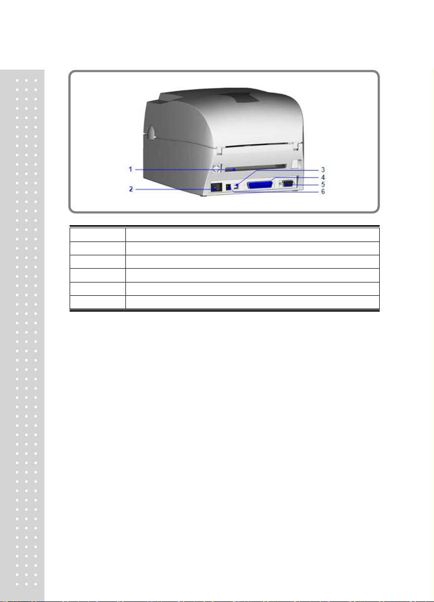
Interfaces Serial Port : RS-232 (DB-9)
USB Port : V2.0
Parallel Port : Centronics 36-pin
Control Panel Two bi-color status-LEDs: Ready, Status
Control key: FEED
Power 100-240VAC, 50/60 Hz
Environment Operation temperature: 41°F to 104°F (5°C to 40°C)
Storage temperature: -4°F to 122°F (-20°C to 50°C)
Humidity Operation: 30-85%, non-condensing.
Storage: 10-90%, non-condensing.
Agency
Approvals CE(EMC), FCC Class A, CB, cUL, CCC
Dimension Length: 11.2” (285 mm)
Height: 6.8” (171 mm)
Width: 8.9” (226 mm)
Weight 2.72kg
Options
Cutter
Label Stripper
External label roll holder for 10” (250 mm) O.D. label rolls
CF card adapter with real time clock (max. 1GB CF card)
* Specifications are subject to change without notice.
6

3) Communication Interface
Parallel Interface
Handshake : DSTB connects to the printer, BUSY connects to the host
Interface cable : Parallel cable compatible to IBM PC
Pin out : See below
Pin No Function Transmitter
1
2-9
10
11
12
13
14
15
16
17
18
19-30
31
32
33
34-35
36
/Strobe
Data 0-7
/Acknowledge
Busy
/Paper empty
/Select
/Auto-Linefeed
N/C
Signal Gnd
Chasis Gnd
+5V, max 500mA
Signal Gnd
/Initialize
/Error
Signal Ground
N/C
/Select-in
host / printer
host
printer
printer
printer
printer
host / printer
host
host / printer
printer
host / printer
Serial Interface
Serial Default Setting : 9600 baud rate, no parity, 8 data bits, 1 stop bits,
XON/XOFF protocol and RTS/CTS
RS232 HOUSING (9-pin – 9-pin)
DB9 SOCKET DB9 PLUG
--- 1 1 +5V,max 500mA
RXD 2 2 TXD
TXD 3 3 RXD
DTR 4 4 N/C
GND 5 5 GND
DSR 6 6 RTS
RTS 7 7 CTS
CTS 8 8 RTS
RI 9 9 N/C
PC PRINTER
7

[Note] The total current output from parallel port and serial port altogether can
not exceed 500mA.
USB Interface
Connector Type : Type B
Pin No 1 2 3 4
Function VBUS D- D+ GND
4) Printer parts
1 Cover Open Button 2 Top Cover
3 Label Roll Core 4 Ribbon Rewind Wheel
5 Print Mechanism 6
Ribbon Rewind Shaft +
Empty Ribbon Roll
7 Locking Tenon(left/right) 8 Front Cover Piece
8

2
1
3
4
5
1 LED Light (READY)
2 LED Light (STATUS)
3 FEED Key
4 CF Card Slot Cover
5 Print Head Pressure Adjustment Screw(left/right)
4
5
1
3
2
1 Ribbon Supply Shaft
2 Label Guide
3 Platen Roller
4 Print Line Adjustment Gear
5 Label Sensor
9

1 Fan-Fold Label Insert
2 Power Switch
3 USB Port
4 Parallel Port
5 Serial Port (RS-232)
6 Power Socket
10

3.Printer Installation
This printer model has the following print modes.
Thermal Transfer (TT) When printing, ribbon must be installed to transfer the print
contents onto the media.
Direct Thermal (DT) When printing, no ribbon is necessary; it only requires
direct thermal media.
Please check the specific print mode, and then go into the Setting Mode after
power on the printer.
1) Ribbon Installation
1. Place the printer
on a horizontal
surface, and open
the top cover by
pressing the Cover
Open Buttons on
both sides.
2. the printer on a
horizontal surface,
and open the top
cover by pressing
the Cover Open
Buttons on both
sides.
11

3. Place a new ribbon
roll onto the ribbon
supply shaft.
4. Feed the ribbon
from the Ribbon
Supply Shaft under
the Print Head.
5. Wrap the ribbon
around the Ribbon
Shaft and stick the
ribbon onto the
Empty Ribbon Roll
Core.
12

6. Firmly close the
upper print
mechanism.
.
13

2) Label Installation
1. Open the top cover by
pressing the Cover
Open Buttons on both
sides.
2. Place the label roll onto
the Label Roll Core.
3. Loosen and lift the
upper print mechanism
by pressing the locking
tenons.
4. Feed the label through
the two Label Guides
to the Tear-off Bar.
5. Align the label guides
to the label edge..
1
4

6. Close the upper print
mechanism from the
top to finish label
installation.
15

3) Label Roll Core Installation Instruction
(A) 1”roll core installation
(B) 1.5”roll core installation
(C) 3”roll core installation
16

4) Card/Hang Tags Installation
When installing cord tags, the tag hole must align
with the sensor arrow (as indicated in figure), then
use the Label Guide to secure the tags.
5) PC Connection
1. Please make sure the printer is powered off.
2. Take the power cable, plug the cable switch to the power socket, and then
connect the other end of the cable to the printer power socket.
3. Connect the cable to the USB/parallel port on the printer and on the PC.
4. Power on the PC and the printer and the printer’s LED light will shine.
1
7

6) Driver Installation
1. Insert the product CD to
your computer’s CD
Drive and find the
"Windows Drives" folder.
2. Select the icon of driver
file and click it to start the
installation.
3. Follow the instruction on
screen to keep the
installation going. Then
the Driver Wizard utility
should run automatically.
4. Select “install Printer
drivers”
5. Select printer model
(BP-1100+).
6. Select connection port.
1
8

7. Enter the printer name
and set printer sharing
option.
8. A description page of
printer settings will be
displayed after all
settings are completed.
9. Check if all printer
settings are correct and
then press Finish to start
copying driver files.
10.Wait for file copying
finished and complete
the installation
11. After the driver
installation is complete,
there should be a new
printer model on
Windows "Printer and
Faxes" setting.
19

4. Accessory
1) Stripper Module Installation
1 Stripper Module
2 Screw(TAP 3x8) x 2pcs
[Note1] Pleasepower off the
printerbeforeinstallingthe
strippermodule.
[Note2] Labellinerthickness
isrecommendedto be
0.06mm±10% withbasic
weight65g/㎡±6%.
2
1
1. Open the top cover by
pressing the Cover
Open Buttons on both
sides.
2. Loosen and then lift the
upper print mechanism
by pressing the locking
tenons.
3. Unlock the front cover
piece by pushing locks
inward.
4. Lift/take off the front
cover piece according to
the direction shown in
the figure.
20

5. Plug in the stripper
connector onto the
switchboard socket.
(refer to the right figure)
[Note] There are 2 sockets
on the converting boards
(one is for stripper
installation, and another
one is for cutter), before
plug the connector into
socket, please check the
pin first.
6. Place the left side of the
stripper first, and then fit
the right side.
7. Hold the stripper module
and tighten the screws.
8. Feed the label through
the Label Guides.
[Note] The label / paper
used for stripper is
suggested to be at least
20mm in height.
[Suggestion] When
printing with stripper
module, it is suggested to
set the stop position (^E) to
9..
21
Table of contents
Other CAS Barcode Reader manuals