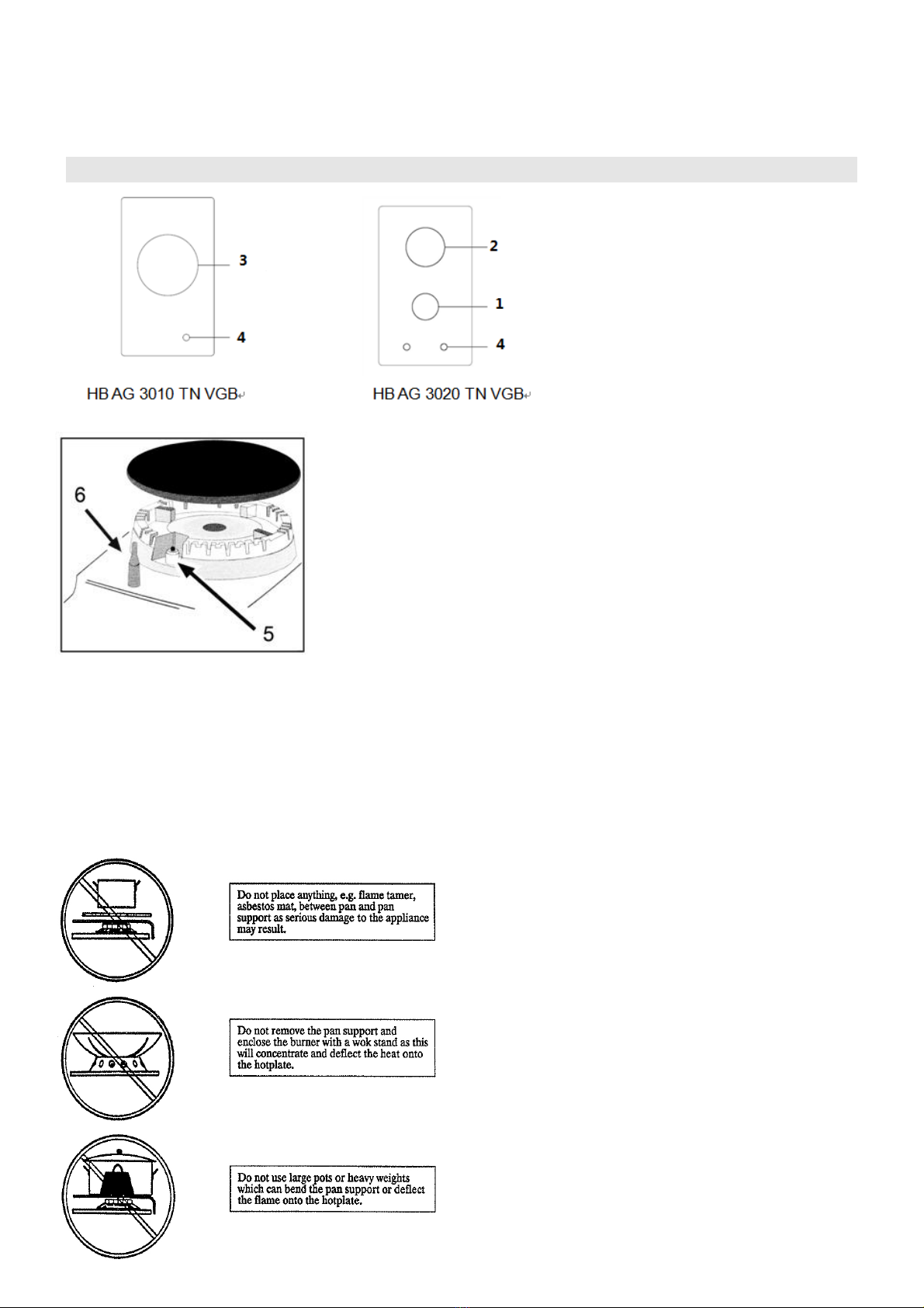
10
IMPORTANCES:
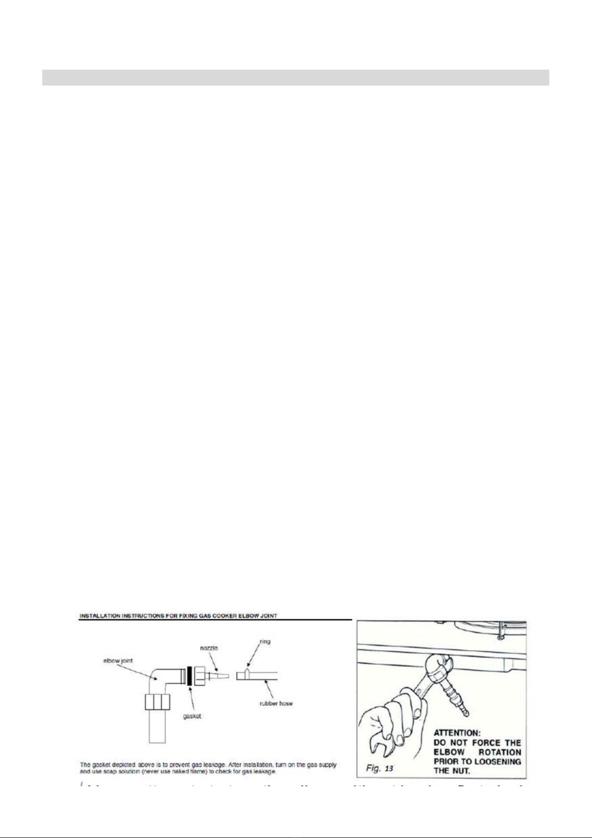
√Never attempts to turn the elbow without having first slackened off the relative lock nipple.
√ The seals are the elements that guarantees the seal in the gas connection. It is recommended that they
be replaced whenever they shows even the slightest deformation or imperfection.
√After connecting to the mains, check that the couplings are correctly sealed, using soap solution, but
never a naked flame.
√The connection with rigid metal pipes should not cause stresses to the hob ramp.
√If the rubber tube is used for the gas connection:
-Make sure the tube is snugly fit at both ends and use a standard tube clamp (not supplied) to fasten it.
-The rubber tube must be as short as possible, without contractions or kinks.
-The rubber tube must never be at any point in its length in contact with the “hot” parts.
-From time to time check to make sure that the rubber is in perfect condition.
OPERATIONS TO BE PERFORMED WHEN SUBSTITUTING THE INJECTORS
If the injectors are not supplied they can be obtained from the “Service Centre”.
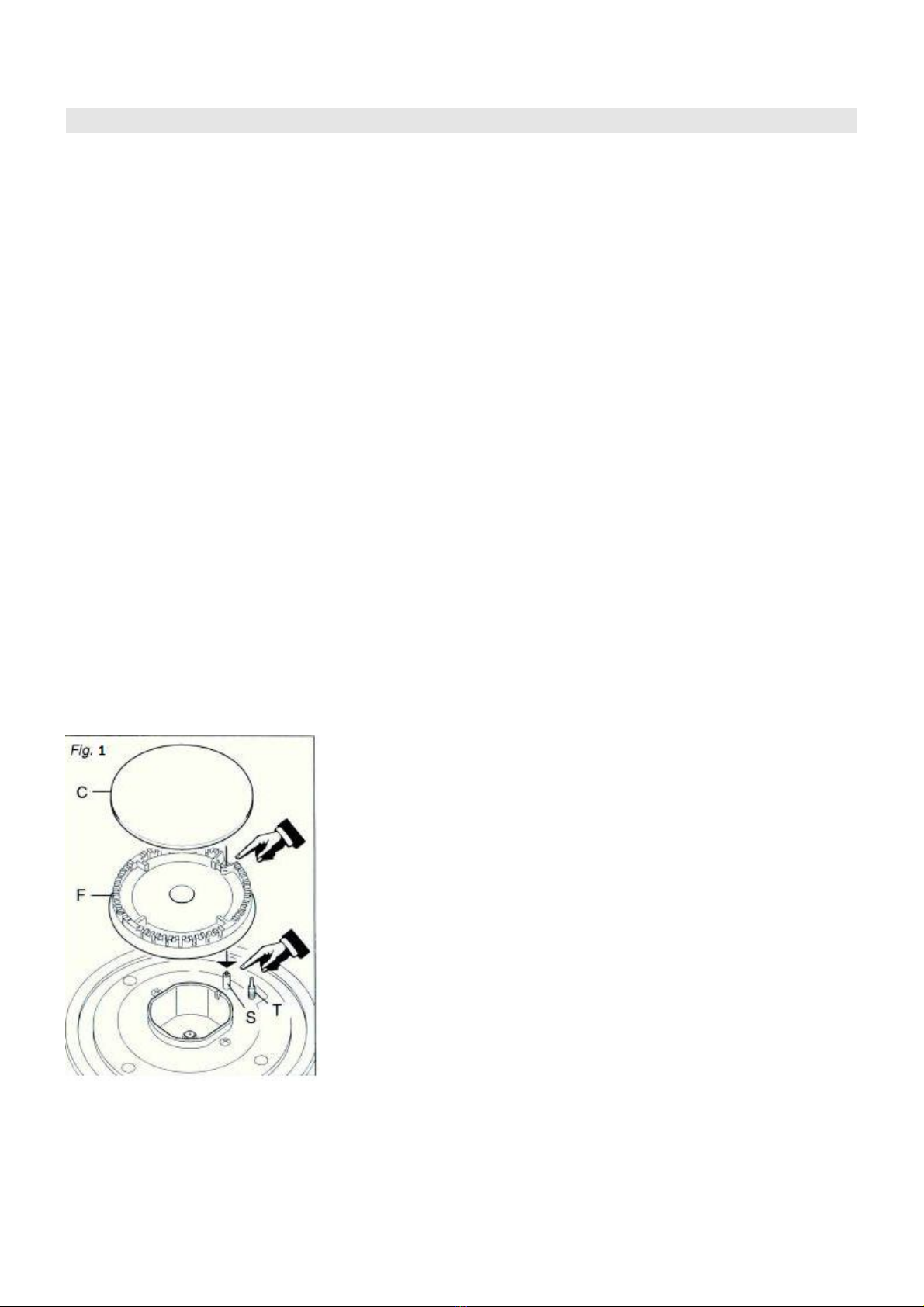
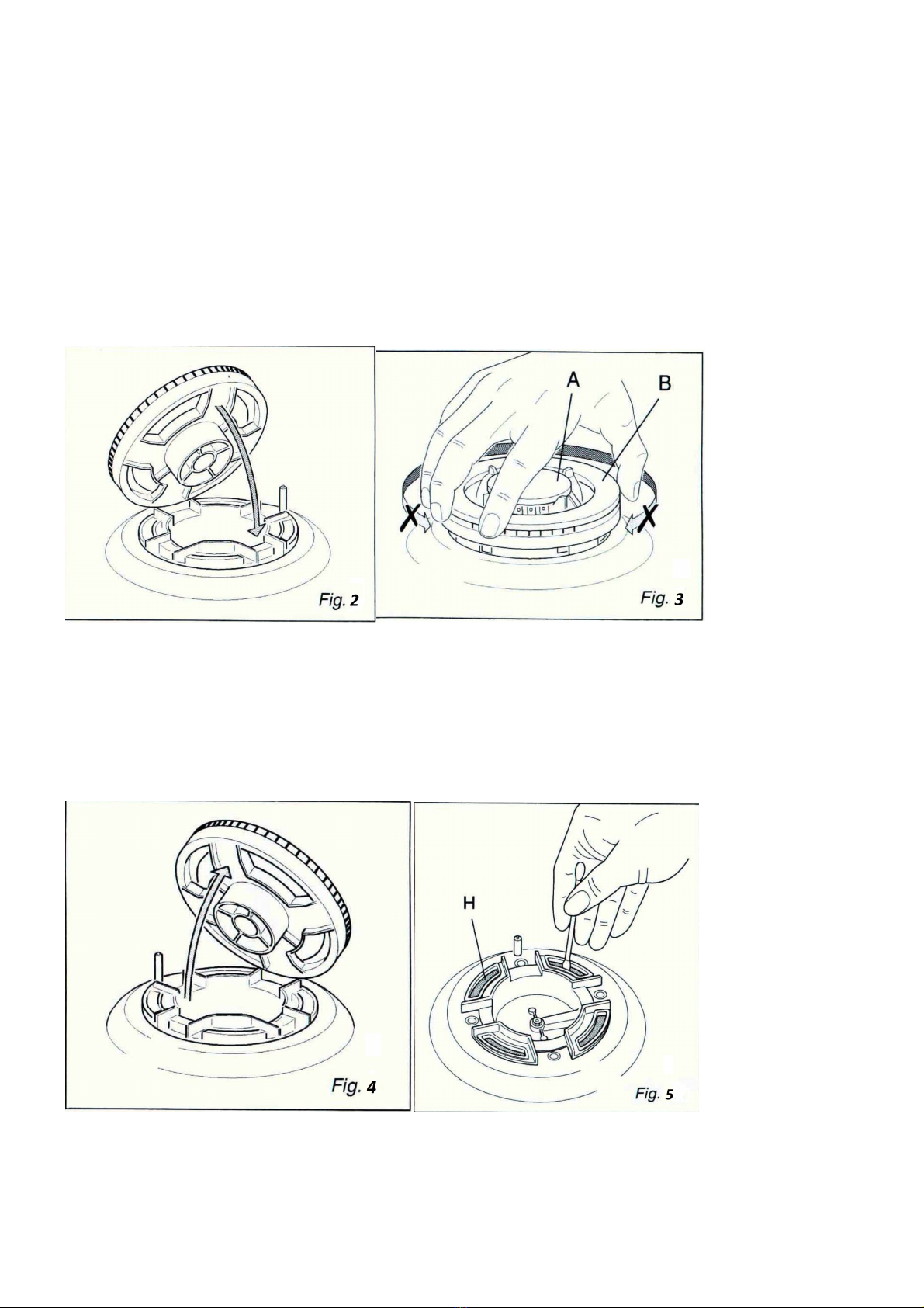
√Remove the gratings and the burner covers;
√Using a wrench, substitute the nozzle injectors; “J” (Fig.14) with those
most suitable for the kind of gas for which it is to be used.
The burners are conceived in such a way so as not to require the
regulation of the primary air.
REGULATING THE BURNER MINIMUM SETTING
When switching from one type of gas to another, the minimum flow rate must also be correct. The flame should
not go out even when passing suddenly from maximum to minimum flame. To regulate the flame follow the
instructions below:
√Light the burner
√Set the cock valve to minimum
On gas valves provided with adjustment screw in the centre
of the shaft (fig.15)
√ Using a screwdriver with max. diameter 3 mm, turn the screw
inside the tap until the correct setting is obtained.
On gas valves provided with adjustment screw on the valve body (fig.16):
√Turn the screw “A” to the correct setting with a screwdriver. Normally for G30 gas, fully tighten the
adjustment screw.