CasaCam VS2104 User manual

VS2104
8 Channel Wireless NVR with
10.1’’ LCD Monitor and 4 1296P Cameras
User Manual

2
Table of Contents
1. SAFETY INSTRUCTION............................................................................................................................................. 3
2. WHAT’S IN THE BOX?.............................................................................................................................................. 3
3. AT A GLANCE........................................................................................................................................................... 4
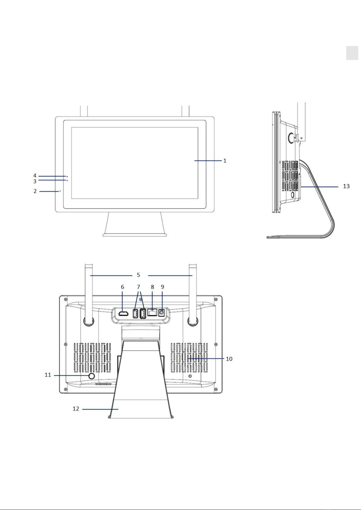
3.1 NVR (receiver)...................................................................................................................................................4
3.2 CAMERA............................................................................................................................................................ 6
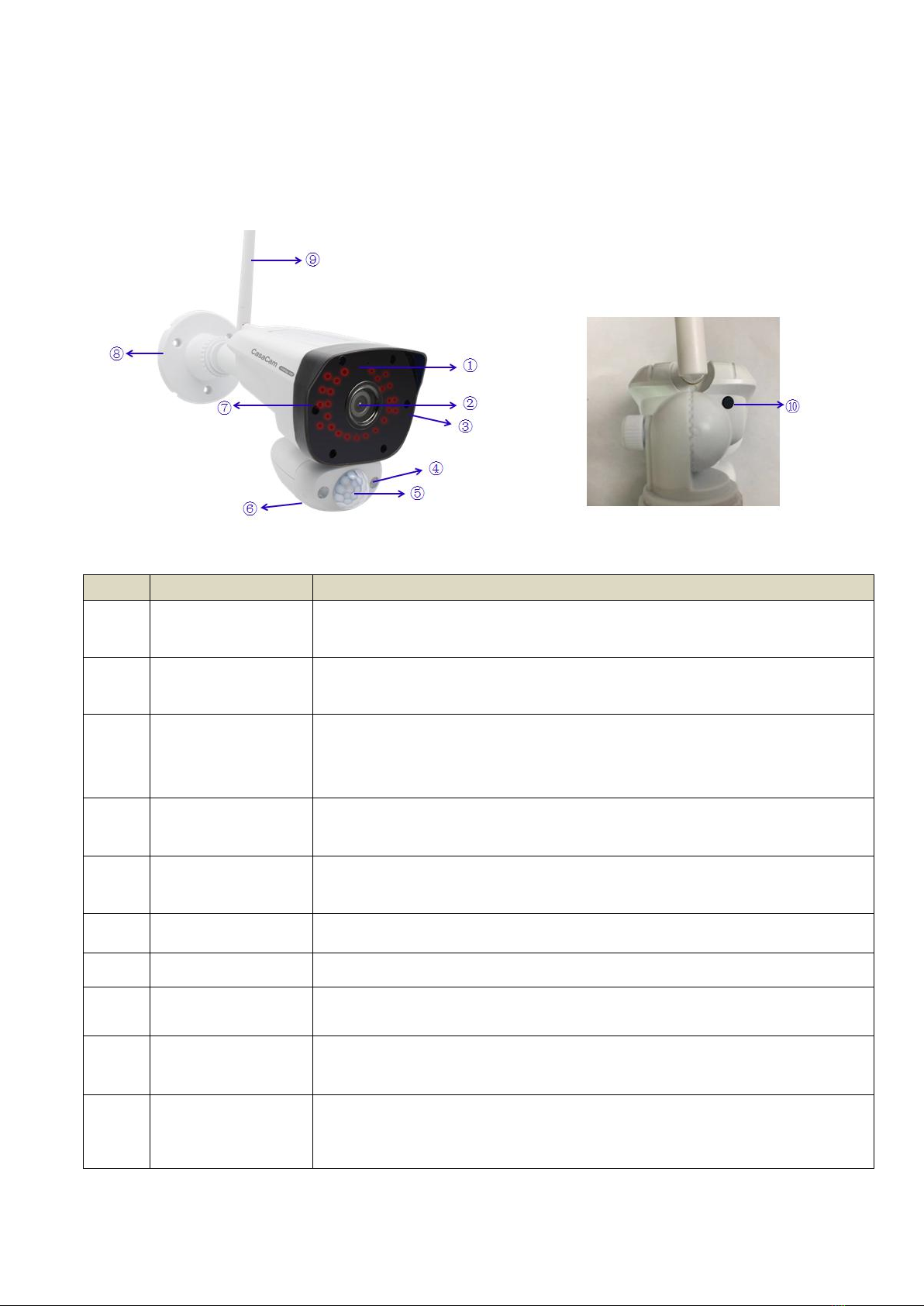
3.2.1 Night Vision Camera.............................................................................................................................. 6
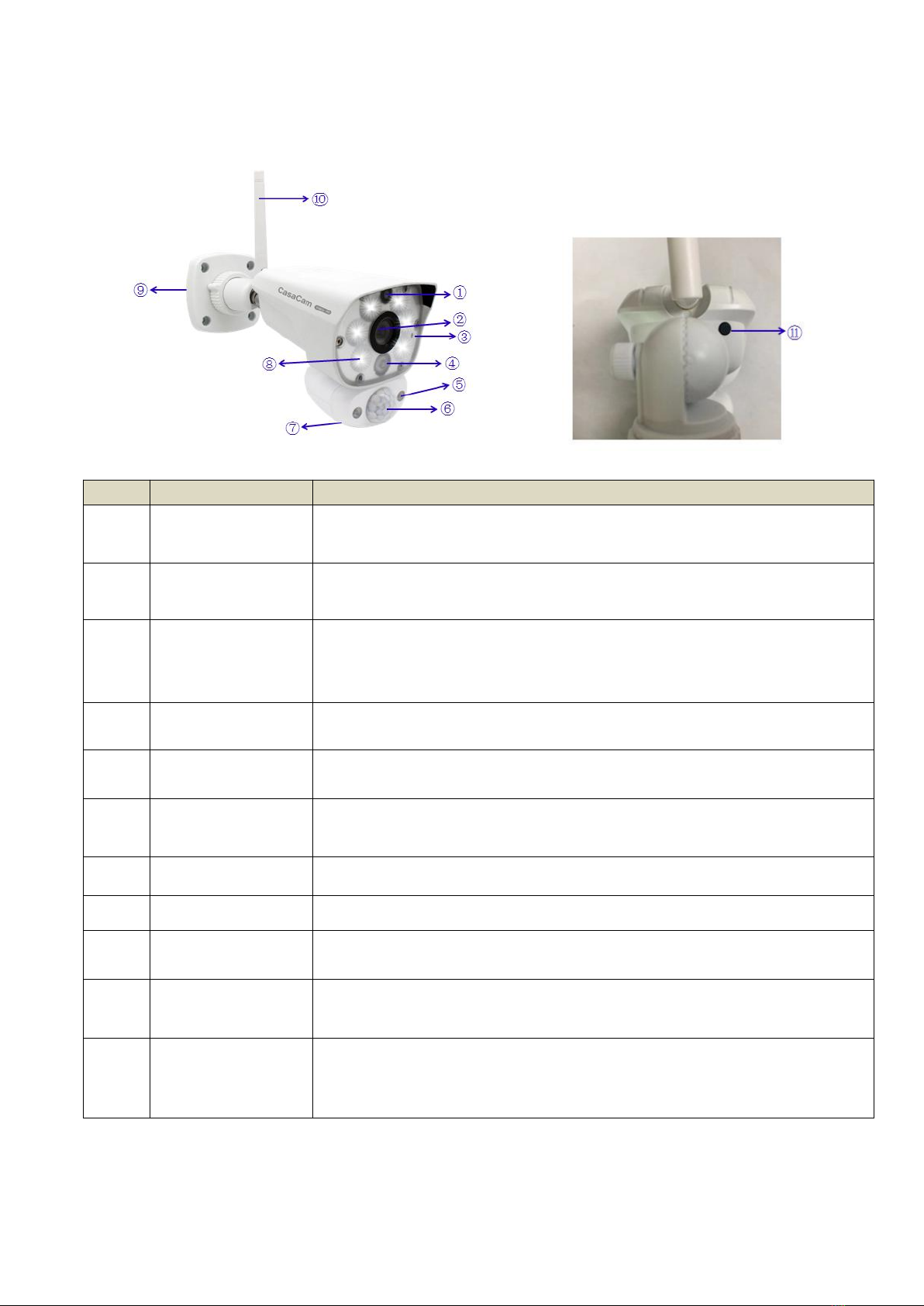
3.2.2 Floodlight Camera..................................................................................................................................7
4. SET UP THE HARDWARE..........................................................................................................................................8
4.1 NVR....................................................................................................................................................................8
4.2 Camera.............................................................................................................................................................. 8
4.3 Set the Antenna Extension............................................................................................................................... 9
5. SYSTEM OPERATION................................................................................................................................................9
5.1 Setup Wizard.....................................................................................................................................................9
5.2 NVR SCREEN....................................................................................................................................................12
5.2.1 Live View Screen..................................................................................................................................13
5.2.2 Log In & Password................................................................................................................................14
5.2.3 Main Menu Toolbar......................................................................................................................15
6. FUNCTIONS........................................................................................................................................................... 15
7.1 Camera & Display............................................................................................................................................16
7.2 Record............................................................................................................................................................. 18
7.3 Playback.......................................................................................................................................................... 19
7.4 Light Setting.................................................................................................................................................... 21
7.5 Motion & Alarm.............................................................................................................................................. 22
7.6 Hard Drive....................................................................................................................................................... 23
7.7 System.............................................................................................................................................................23
7.8 Advanced........................................................................................................................................................ 24
7. REMOTE FROM APP.............................................................................................................................................. 24
8.1 Get the App.....................................................................................................................................................24
8.2 APP Remote.................................................................................................................................................... 25
8.2.1 Add camera..........................................................................................................................................25
8.2.2 Operating the App............................................................................................................................... 26
8. SPECIFICATIONS.................................................................................................................................................... 28
9. TROUBLE SHOOTING.............................................................................................................................................30
10. FCC REGULATIONS................................................................................................................................................ 31

3
Please read carefully before using this equipment.
1. SAFETY INSTRUCTION
1Install the NVR in sufficiently ventilated spaces to prevent plug vents.
2Install the NVR on a flat wall or other flat surfaces, avoid mounting in a severe vibration environment.
3Only use the power adapter plug contained in the material supplied since other power adapter plugs
could damage the devices. Ensure access to the power adapter plug is not obstructed by
furniture or such. Pay attention that the plug and cable are in perfect condition. Kinked or worn cable
represents the risk of a fatal accident!
4Unauthorized modification or reconstruction is not permitted. Under no circumstances open the
devices or complete any repair work yourself. Observe all local directives and regulations.
2. WHAT’S IN THE BOX?
10.1 Inch NVR
Mouse
Adapters
(4pc for camera, 1pc for NVR)
Ethernet Cable
User Manual &
Quick Start
Guide
Screws and Anchors
kit
1TB HDD
(pre-installed)
Antenna Extension
(With Magnetic
Stand Base)
VC2000
Night Vision Camera*3pcs
VC2000L
Floodlight Camera*1pcs

4
3. AT A GLANCE
3.1 NVR (receiver)

5
Item
What it is
What it does
1
NVR Screen
10.1” LCD panel
2
Microphone
Captures the sound on monitor and transmits the sound from
monitor to camera. (Intercom)
3
Power Indicator
The indicator LED will turn on when NVR is powered
4
HDD Indicator
The indicator LED will turn on when HDD is installed
5
NVR Antenna
Transmitting wireless signal with wireless camera.
6
HDMI port
Connect the HDMI cable
7
USB port
Connect the mouse to control the NVR or connect to USB storage
for back up.
8
RJ-45 port
Connect the Ethernet cable to get access to enable
Smartphone/tablet connectivity.
9
Power port
DC 12V power port. Connect to a local power outlet using te
included 12V power adapter.
10
Speaker
Produces the sound transmitted from cameras.
11
Screen ON/OFF &
Auto Config Button
* Press the button to turn ON/OFF the screen (enter/exit power
save mode, with only audio on)
* Press and Hold the button to use the AUTO CONFIG setting.
When you adjust the display resolution, displayed picture may not
in the center of the screen. In this case, you can use auto config to
adjust the picture to central position.
12
NVR Stand
Stand the NVR on table or other flat surfaces. You can also mount
the stand to the wall.
13
HDD compartment
Open up the cover to install the HDD (2.5"). Close the cover after
installation

6
3.2 CAMERA
3.2.1 Night Vision Camera
Item
What it is
What it does
1
Microphone
Captures the sound on camera side and transmits the sound from
camera to monitor.
2
Lens
Catches the video in front of the lens and transmits video from
camera to Monitor.
3
Working Indicator
Indicates the working status of camera. (Green LED)
Flashing rapidly——Ready to pair/ pairing mode
Solid green——Paired / working
4
Light sensor
Sensing light and give order to the IR cut to switch between
daytime and night vision mode.
5
PIR sensor
Detects motion in front of the lens and emits detection signal to
transmitter.
6
Speaker
Produces the sound transmitted from the monitor.
7
IR LED
Infrared LEDs provide viewing in no/low light conditions.
8
Bracket
Use the bracket to mount the camera on a wall or other flat
surfaces.
9
Camera antenna
Receives & Sends signals to or from the Monitor.
10
Reset button
The reset button is located on the back of the camera. Press and
hold the reset button (until the indicator LED flashes) to reset the
camera.

7
3.2.2 Floodlight Camera
Item
What it is
What it does
1
Microphone
Captures the sound on camera side and transmits the sound from
camera to monitor.
2
Lens
Catches the video in front of the lens and transmits video from
camera to Monitor.
3
Working Indicator
Indicates the working status of camera. (Green LED)
Flashing rapidly——Ready to pair/ pairing mode
Solid green——Paird / working
4
IR LED
Infrared LEDs provide viewing in no/low light conditions.
5
Light sensor
Sensing light and give order to the IR cut to switch between
daytime and night vision mode.
6
PIR sensor
Detects motion in front of the lens and emits detection signal to
transmitter.
7
Speaker
Produces the sound transmitted from the monitor.
8
Floodlight
White LED floodlight.
9
Bracket
Use the bracket to mount the camera on a wall or other flat
surfaces.
10
Camera antenna
Receives & Sends signals to or from the Monitor.
11
Reset button
The reset button is located on the back of the camera. Press and
hold the reset button (until the indicator LED flashes) to reset the
camera.

8
4. SET UP THE HARDWARE
4.1 NVR
1Place the stand on the back of the NVR on a table or install to other flat surfaces, position the
antenna.
2Connect the mouse to the mouse port on the back of the NVR.
3Connect an AC adaptor to the power input on the back of the NVR. Connect the other end of the
adapter to a standard indoor power outlet. The NVR will power on automatically and start initialize,
Please wait until initialization is completed.
4The screen of NVR remains dark until the cameras are powered on.
4.2 Camera
General
The camera included with your monitor is weatherproof and have an IP66 rating. Water can be sprayed
on them and they will still work; however, the cameras cannot be submerged.
Although the cameras can be exposed directly to the rain, it is recommended that, if they are used
outdoors, they should be mounted under some type of cover like a patio overhang or eave. As rainwater
drops start to dry on the camera glass, it can create spots that will reflect the light from the infrared LEDs
used for night vision, thus causing lower quality video.
Also, as dust, grime, and cobwebs accumulate on the camera glass, they can reflect light from the
infrared LED and might lower video quality. Periodically clean the lens glass with a soft cloth.
Placement Considerations
Consider the following when placing cameras:
• The clearest line-of-sight between the camera and NVR is best.
- Walls, especially brick and concrete, shorten the transmission distance.
- Placement next to windows allows better transmission.
• Optimized motion detection range is 6~30 feet for the camera. The farther away an object is, the less
accurate the motion detection.
• Avoid having a direct light source in the view of the camera, including street lights, ceiling or floor lamps,
spotlights in the driveway, etc.
• Rainfall, pool water ripples/reflections, tree/shrub leaves blowing in the wind – and the shadows they
create can generate motion detection false alarms.
• When you are positioning the camera, bring the monitor along; it’s much easier to get the camera into
the right position when you have the display handy.

9
Install the Camera(s)
1Position the camera where you want it, plug it into power, and check video on the NVR. Move the
camera if the view is not what you want.
2Hold the base of the camera stand where you want to mount it and mark the location of the screw
holes.
3Use the included screws and anchors to attach the base to the wall or ceiling.
4Tug gently on the stand to make sure it is securely in place.
4.3 Set the Antenna Extension
The included antenna extension is supplied to extend the transmitting distance between the camera and
NVR and provide a better signal.
You can use the included Antenna Extension cable
if your setup requires the signal be transmitted
through an obstacle that severely weakens it.
Simply replace the camera antenna with the
Antenna Extension cable and mount it on the
opposing side of the obstacle.
5. SYSTEM OPERATION
5.1 Setup Wizard
Before using the system, please follow the setup wizard to set your system.
NOTE: Among this section, for each step, on the bottom will display a notification to let you
select/unselect.
Default value: select.
Select means next time you reboot/turn on the NVR, system will remember your previous setting and skip
the setup wizard surface to enter the live view section directly.
Unselect means you have to follow the setup wizard every time reboot/turn on the NVR.

10
1Setup New Password
The default user name is “admin”.
Please enter your new password and confirm the new
password.
Select Remember Password, the system will remember
the password you have set.
After confirm the new password, click Next to enter the
next step.
Note: Password should be 4~10 digits. The password can be letter(s) and/or
number(s). Do not use symbols or space in password.
2General System Configuration
This step allows you to set below items:
Date
System Time
Date Format
Time Format (12h or 24h)
Language
Menu Timeout
Confirm above then click Next to enter the next step.
3HDD management
This section display the hard disk list, you can check the
basic information of your HDD (model/capacity/used
space/status).
Select here then click Formate to format
the HDD.
Select here to enable the overwrite
function.
Overwrite on: system will overwrite earliest recorded files when HDD is full.
Confirm above then click Next to enter the next step.
4Record Schedule
Channel
Select the Channel you want to set.
Copy To
Select here copy the same setting to any channel or all channels.
Select the type of recording you’d like to activate

11
Recording setting type: Continuous, Motion, No Record
Left click and drag the table to fill the desired date and time blocks.
A. Under Continuous type, the filled blocks are in GREEN.
During the filled date and time blocks, NVR will keep recording continuously.
B. Under Motion type, the filled blocks are in YELLOW.
During the filled date and time blocks, NVR will record once motion is detected.
C. Under No Record type, the filled blocks are in blank.
D. Confirm above then click Next to enter the next step.
5Remote Viewing Setup
Download the WNVR Pro App on your mobile device and scan this QR code of this NVR for remote
viewing.
For more information, please refer to user manual or quick start guide.
NOTE: Make sure NVR is connecting to your local router by Ethernet cable.

12
After finishing upon setting, then click DONE to complete it and enter to live view screen.
5.2 NVR SCREEN
The NVR’s screen has 3 main parts:
•Live View area. The main screen area displays live video from the camera(s).
• Main menu. Those menus allow you to manage the system.
• Icon bars. Most of icons display on the top and bottom of the live view screen.
Viewing Modes
The Live View area displays live video from the cameras. Each camera can display in its own section of
the screen (quadrant) or full screen.
There are multiple viewing modes:
• Quad Mode. Splits the screen’s image area into 4 quadrants and displays active camera video in each
quadrant.

13
Default: 4 CH split screen.
NOTE: System is expandable to 8 CH, go to section 7.1 to set 8 CH view.
•Single Channel View. Double click the center of the quadrant to enter Single Channel View mode.
Under Signal Channel Mode, double left click the screen to exit then back to Quad Mode.
•Auto Switch. Move the mouse over the bottom of the display, selected the Auto Switch Icon and click
the icon to turn it to blue, NVR will switch each channel automatically in full screen display.
5.2.1 Live View Screen
1
Date & Time
Displays the date & time
2
PIR Working Indicator
Displays when motion is detected by PIR
3
Recording Indicator
When this icon displays, it indicates that
recording is in progress.
4
Signal Strength
Shows how strong the camera's signal is.
Signal ranges from 4 bars down to 0 bars (out
of range).
5
Channel
Displays the camera number

14
Number(camera
number)
6
Intercom
Click here to activate intercom feature to talk
back to the camera.
7
Floodlight Control
Click here to turn the camera floodlight on/off
manually.
8
Zoom
Click the area you would like to zoom. Scroll up
the mouse to Zoom in, scroll down to zoom out.
9
Color Adjust
Click here to adjust Hue, Brightness,
Saturation, Contrast, Sharpness.
You can also click the quick setting icon:
Default, Bright and Soft.
NOTE 1: Under single view, left click the mouse, toolbar will displays.
NOTE 2: Beside manually controling the light, the system also allows automatic setting--Dusk to Dawn or
Customer Schedule. For the details, please go to section 7.4 LIGHT SETTING.
5.2.2 Log In & Password
To access the setting toolbar or menu, system request to enter your system password.
The default user name is “admin”, and the system will require you to set up a password when you log in
for the first time.
Modify Password: Main menu → System → Users→ Set password → Confirm password → OK → Save
& back
Password protection: When enter a wrong password more than 5 times (including 5 times), the system
will be locked.
In case you forget the password to access the system, please follow below step to reset the password.

15
5.2.3 Main Menu Toolbar
Move the mouse cursor to the bottom of the screen, below toolbar will display automatically.
Click here:
Main menu: click here to enter main menu.
Click here to lock the toolbar.
When you select the lock, you have to enter your Password and click OK to
save the setting.
Click this icon again to unlock the toolbar.
BLUE icon: locked
WHITE icon: unlock
Note:
If the toolbar is locked, you can only double-click the left key of mouse to
switch the viewing mode between single view and QUAD view.
You can set up the auto lock time at System/ General/ Menu timeout
Click here to enter/exit Sequence Mode
BULE icon: system in Sequence mode, monitor will display from channel
1—channel 2---channel 3- channel 4 sequentially.
WHITE icon: not in Scan Mode.
Click here to set the volume. Click – to turn down, click + to turn up.
Click here to play back the recorded videos.
Click here to set the video detection ( channel、sensitivity alarm interval)
6. FUNCTIONS
You can manage the system through the main menu..
Click icon to enter main menu section.

16
7.1 Camera & Display
Click , to enter the video managing surface.
1Cameras
Select the camera which you want to set. Modify channel name, enable/disable the audio from
camera.
2Display
OSD Alpha: set the brightness of screen background. Click+ to turn dark, click- to turn light.
Display resolution: select from 1024*768,1280*1024,1366*768,1440*900,1080p@50Hz,
1080p@60Hz.
Slide Show Interval: In auto switch mode, you can select the switch interval for each channel from 2
seconds-5 seconds, 8 seconds or 10 seconds.(2.3.4.5.8.10 five options)
3Camera Setup
NVR supports a total of 8 active cameras at a time, this system VS2102 model includes 4 cameras (3pcs
of night vision cameras and 1 pc of flood light camera, those included cameras are already paired.
VS2102 support below 2 models additional camera:
VC2000- Casa Cam night vision camera
VC2000L: Casa Cam flood light camera
When you add the additional camera, you have to pair it to the NVR (that is, you have to “introduce” the
camera and NVR to each other so they can communicate).
Plug the camera into power before pairing.
Pair

17
1. Click the channel you want to pair the camera to, click
Pair.
2. Check the status of camera working indicator:
Quick flashing: under pairing mode
Slow flashing: unpaired or out of range
Solid green: paired
Please make sure the camera is powered on, then press and hold the pair button ( on the back of the
camera) about 5 seconds until the working indicator light turn off, then wait until the working indicator
is flashing quickly, means the camera is ready to pair.
3. Check the NVR screen, when the camera is under pairing mode, NVR will search the IP and display it
on the screen, that means the camera and NVR are paired.
You can also check the working indicator of the camera, solid green light means well paired.
4. Click exit and back to LIVE VIEW screen.
NOTE:
Make sure the camera is powered on before pairing.
If a camera is already paired to the channel, while you want to re-pair the camera to the NVR, please
delete the existing channel on the NVR first.
Delete
Select the channel and click Delete, the camera will be deleted from NVR.
Delete All
Click here all the channels will be deleted.
Repeater
When the distance between camera and NVR is beyond the transmission range, you can use the
Repeater function to expand the transmission range.
1Click to enter repeater setting surface. The system will check the current net connection
status automatically, please wait until display “DONE”, then click OK to enter the setting surface.

18
2Click to add a camera from another 3 cameras.
For example, click on the right of CH1, then select CH4. That means, CH4 will transmit the signal
through CH1, finally transmit to NVR. Bring both cameras near the NVR to set up the repeater feature.
3Click Aplply or OK to save the setting, click Refresh to refresh the connecting datas.
Click Cancel to return to previous screen.
NOTE:You can repeat MAX 2 cameras for a repeater connecting.
4Delete the repeater camera.
Move the cursor to the CH you want to delete, click the left key of the mouse, then click Apply or OK to
save the setting, click Cancel to quit the setting.
NOTE:
Make sure the camera is powered on before setting.
Make sure the bridge camera is working normally (within the signal transmitting range), otherwise the
repeater function won’t work.
7.2 Record
Click to enter record setting surface.
Channel

19
Select the Channel you want to set.
Copy To
Select here copy the same setting to all channels.
Select the type of recording you’d like to activate
Recording setting type: Continuous, Motion, No Record
Left click and drag the table to fill the desired date and time blocks.
E. Under Continuous type, the filled blocks are in GREEN.
During the filled date and time blocks, NVR will keep recording continuously.
F. Under Motion type, the filled blocks are in YELLOW.
During the filled date and time blocks, NVR will record once motion is detected.
G. Under No Record type, the filled blocks are in blank.
After setting, click Save & Back to complete the setting & back to previous surface.
7.3 Playback
Click , to enter play back surface.
1Select the DATE & TIME
2Select the channel to filter the videos.

20
Select channel from 1-8, you can select the channel you would like to review. You can also select
several channels a time and filter the video out. When filtering the video, system loads up to 4
channels at a time.
3Select Continuous, filter the videos under continuous recording mode.
4Select Motion, filter the videos under motion recording mode.
5Click Search to load the recorded file, among the file list, select the file you’d like
to play, click File Playback to play it.
6From the file list, the selected file can be backed up by clicking Backup (make
sure NVR connected USB storage before backup). Select video format avi or
mp4 before back up.
You have to back the file up one by one (do not support bulk back up).
7
This section allows you to review all the recorded videos quickly which happened within a day.
Click Hour, to filter the exactly time and load the videos out.
Drag the progress bar to review the recorded events.
Click here to play the video.
Click here to pause the video
Click here to fast play the video.
Shows the speed of the video playing.
8Click Exit to exit and back to previous surface.
Table of contents
Other CasaCam Digital Camera manuals