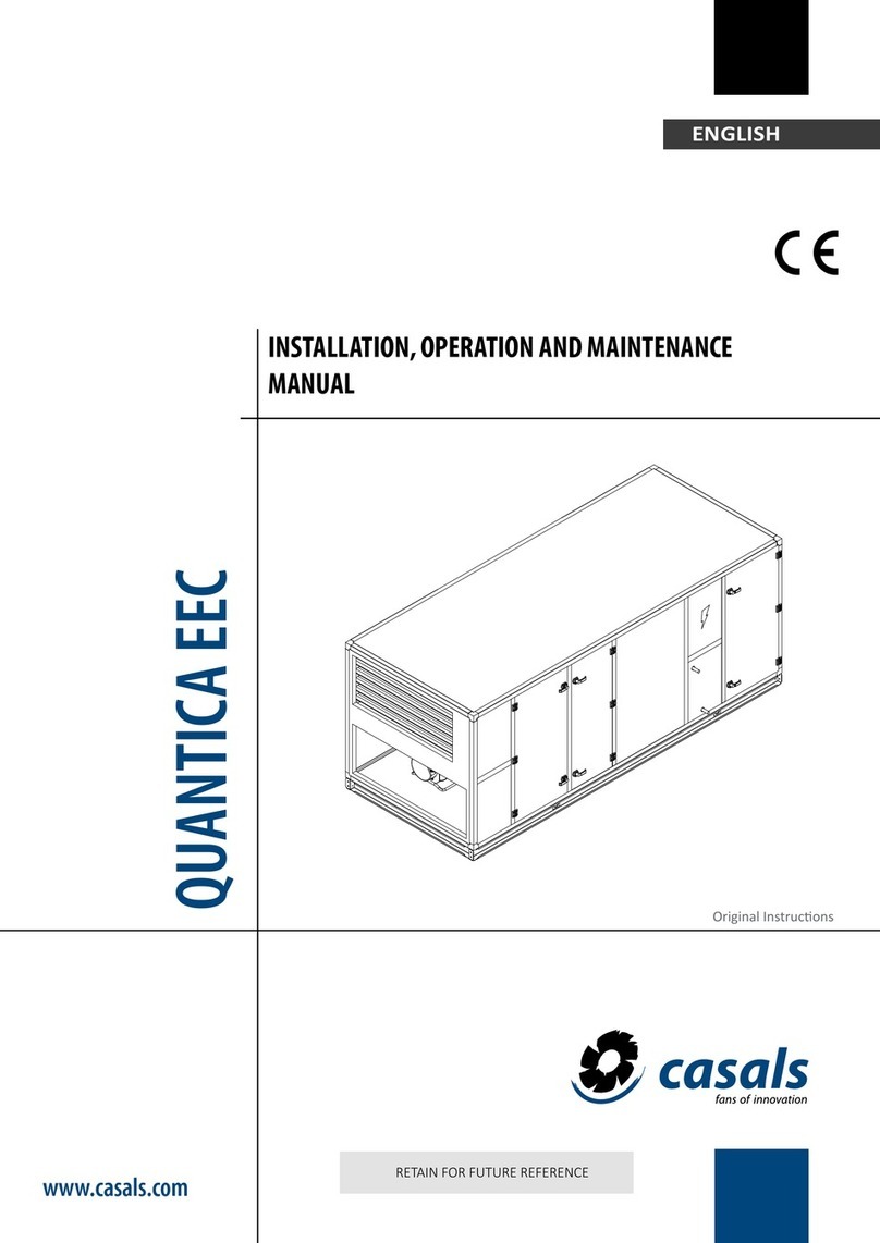
Casals ABRENSA EEC User manual

www.casals.com
CV082021-1
ABRENSA EEC
USER MANUAL AND INSTALLATION

2
CV082021-1
INDEX
DESCRIPTION p. 3
INSTALLATION p. 3
MAINTENANCE p. 3
EQUIPMENT WARRANTY p. 4
APPLICATION SETTINGS FOR THE UNIT p. 5
CONFIGURATIONS p. 6
CONDENSED BOARD p. 7
WIRING DIAGRAMS - FANS p. 7
ACCESSORIES - CUTTING SWITCH p. 8
ACCESSORIES - PRESSURE p. 8
ACCESSORIES - CONSTANT FLOW p. 9
ACCESSORIES - CO2 CONTROL p. 10
ACCESSORIES - WATER COIL p. 11
ACCESSORIES - ELECTRICAL COIL p. 11
ACCESSORIES - WATER COIL FOR HEATING / COOLING p. 11
ACCESSORIES - DIRECT EXPANSION COIL p. 12
ACCESSORIES - ATTENUATION MODULES p. 12
ACCESSORIES - ELECTRIC COIL p. 13
CE DECLARATION OF CONFORMITY p. 15

3
CV082021-1
ABRENSA EEC
DESCRIPTION
ABRENSA EEC are heat recovery units that allow you to take advantage of the energy exchange between indoor and outdoor airflows. Its
versatility of installation and the high number of possible configurations give this big equipment an adaptability to any type of building that
can be installed on the outside as well as inside.
INSTALLATION
As with any equipment, ABRENSA EEC heat recovery units must be properly installed and serviced in a manner that ensures their correct
operation from the time of commissioning and during the life of the equipment and the following recommendations must be complied
with, valid for the equipment in question.
Warnings
• The mains to which the appliance is to be connected must comply with the regulations in force.
• The appliance must be properly connected to an efficient earth connection, as provided for in the current electrical safety regulations. In
case of doubt ask for the control of the network by qualified professionals.
• The appliance must only be installed and used in accordance with the regulations in force, for the purpose for which it was designed. Insta-
lling it and using it differently or with strange accessories can be dangerous.
• The manufacturer can not be held liable for damages that may result from improper installation, use or maintenance, and /or from repairs
by unqualified personnel.
• Never use the unit to support other equipment.
• Before opening the unit door, make sure that all electrical parts have been turned off.In particular, make sure that the fan is turned off and
can not be inadvertently turned on.
• Beware of any sharp edges that may exist inside the unit.
• Never climb or walk on the unit.
• Required installation of local cut-off switch.
• Mobile Parts - Before performing any intervention, make sure that the fan is completely stopped.
• The accessories listed in the appendix can already be properly connected depending on the options requested when ordering the equipment.
• Read this entire manual before using the equipment.
Starting the equipment
• Check that there are no foreign bodies inside the module.
• Check that the turbine rotates freely, without contact with the fan housing or other elements.
• Check that the power supply characteristics are correct for the motor in question and ensure that the equipment is connected to an effi-
cient earth connection.
• The motor should be electrically supplied according to the instructions given in this manual in the chapter “Electrical Schemes - Fan” and
check that the direction of rotation of the turbine is correct.
• With the access covers closed, check that the electrical consumption of the motor is in accordance with the nameplate. Caution:The absor-
bed current must never exceed that indicated on the motor nameplate.
• Check that there are no vibrations or abnormal noise.
• The unit comes with plastic film in the panels for protection during manufacture, transportation and installation. Once the installation is
complete, this protective film should be removed.
MAINTENANCE
Recovery units periodically require maintenance to correctly perform the function for which they are designed. The frequency with which
the maintenance is performed depends on the environmental characteristics where the equipment is inserted and the number of hours of
operation, so that the following is to be considered as a guide.
Fan
Operations to be carried out:
• Check that there are no foreign bodies inside the module.
• Check tightness of wiring.
• Check that the turbine rotates freely.
• Check tightness of all screws to avoid undesirable vibrations.
• General interior cleaning
Frequency of maintenance: Semester.

4
CV082021-1
Filters
Operations to be carried out:
• Check that there are no foreign bodies inside the module.
• Check tightness of all screws to avoid undesirable vibrations.
• Check that the filter cloth is not cut.
• Check the condition of filter fills (replace if necessary).
• General interior cleaning
Frequency of maintenance: Monthly
Heat recover
Operations to be carried out:
• Check that there are no foreign bodies inside the module.
• Check tightness of all screws to avoid unwanted vibrations.
• Check the condition and fix and clean the recovery element
• Check condensate sewage, clean and sanitize the condensate tray.
• Check bypass operation
• General interior cleaning
Frequency of maintenance: Semiannual
Water tank and direct expansion
Operations to be carried out:
• Check that there are no foreign bodies inside the module.
• Check tightness of all screws to avoid unwanted vibrations.
• Check coil connections.
• Check and clean (if necessary, taking care not to damage) the fins of the batteries.
• If there are deformed fins, replace them in the correct position with a suitable “comb”.
• General interior cleaning.
• Check condensate drain when applicable, clean and sanitize the condensate tray.
Frequency of maintenance: Semiannual
Resistance coil
Operations to be carried out:
• Check that there are no foreign bodies inside the module.
• Check tightness of all screws to avoid unwanted vibrations.
• Check connection status by replacing cables and redoing connections if necessary.
• Check the safety thermostat.
• General interior cleaning.
Frequency of maintenance: Semiannual
Acoustic Attenuators
Operations to be carried out:
• Check that there are no foreign bodies inside the module.
• Check tightness of all screws to avoid unwanted vibrations.
• Check the condition and setting of the acoustic baffles.
• General interior cleaning
Frequency of maintenance: Annual
EQUIPMENT WARRANTY
Casals Ventilación warrants this product against all manufacturing defects for a period of 2 (TWO) years after the date of purchase.
Technical assistance under warranty will only be provided upon presentation of the purchase document, which proves that the equipment
is within the warranty period.
If, during the warranty period, the product is experiencing problems resulting from manufacturing defects, Casals Ventilación or its Authori-
zed Technical Services will, without any charge for repair at their premises or (at Casals Ventilación’s discretion) replace the product or place
to the customer’s disposal the components to replace the defective ones in accordance with the following conditions.
Casals Ventilación reserves the right, in its sole discretion, to replace defective product components or small value products, either by new
components or products, or by components or recycled products. This warranty covers only the equipment and no costs and losses are in-
curred as a result of equipment shutdown and are therefore expressly excluded.

5
CV082021-1
PROBLEM POSSIBLE CAUSE CHECK POSSIBLE SOLUTION
Motor in very high
consumption
Operating point different from that
expected;
Excess flow;
Create a loss of load in the installation;
Fan speed;
Reducir la velocidad de rotación;
Crear una pérdida de carga en la
instalación;
Excess air flow
Air distribution system, pressure drop
in the oversized installation;
Check the flow and the pressure drop;
Reduce rotation speed;
Fan speed;
Create a loss of load in the insta-
llation;
Insufficient air
flow rate
Air distribution system, underestima-
te installation pressure drop;
Check flow and pressure drop
Fan speed;
Filtration filter;
Increase the speed of rotation (ac-
cording to available motor power
and maximum fan speed);
Replace filter;
Excessive noise
Flow too high, speed too high;
Load loss too high;
Check the flow and the loss of charge;
Decrease flow rate;
Avoid areas of unstable operation
of the fan;
Damaged bearings, damaged metal
components;
Unbalanced moving components;
Bearings,condition of the components;
Strange vibrations;
Replace bearings, damaged com-
ponents;
Replace fan;
Drive does not
work Power failure;
Power supply;
Circuit breaker;
Restore power supply;
Resetting circuit breaker;
Low efficiency
of the recovery
Dirt in the recovery element; Cleaner state of the stove; Clean recuperator;
Low flow rate Filter embedding Replace filter
TROUBLESHOOTING
Note: Please note that heat recovery units are integrated into a general system. For this reason, failures may be caused by other system
components, improper interaction between the drive and the system, or environmental conditions other than those specified for the drive
design.
Warranty exclusions
• Natural wear parts.
• Parts that are subject to deterioration or breakage,eg belts, filters,fuses,etc.
• Malfunctions caused by misuse, abuse, neglect, negligence, lightning, flooding, humidity, falls, collisions, accidents and transportation.
• Malfunctions caused by the use of the equipment for unintended purposes.
• Malfunctions occurring as a result of manipulation, modification or repair of the equipment by unauthorized persons or technical services
or by the application of improper parts or accessories.
• Malfunctions caused by improper or illegal installation (voltage,water pressure or other), power failures, disregard for instructions.
• Aesthetic wear or deterioration caused by use, changes in color, oxidation or corrosion of the apparatus or its components.
• Any repairs do not have the effect of prolonging the warranty, nor does it give rise to any indemnification.
The guarantee shall not be valid if:
• Make sure that the equipment nameplate has been tampered with or tampered with.
• False data is provided.
• The equipment is not accompanied by the purchase document.
• The equipment has been tampered with, modified or repaired by unauthorized persons or technical services.
• Verification / maintenance operations are not carried out or are carried out by unauthorized technicians.

6
CV082021-1
A
FV
AV BV CV
DV EV
B
GV
CD
EF
GH
IJKL
MN OP
CEPHIRUS-2 & CEPHIRUS-2 EEC HORIZONTAL
CEPHIRUS-2 EEC VERTICAL
Aire nuevo
Aire extraido
A
FV
AV BV CV
DV EV
B
GV
CD
EF GH
IJKL
MN OP
CEPHIRUS-2 & CEPHIRUS-2 EEC HORIZONTAL
CEPHIRUS-2 EEC VERTICAL
Aire nuevo
Aire extraido
Directives: Standard rules:
• Machinery Directive 2006/42 / CE • EN 60335-1: 2010
• EN 60947-3: 2009
• Low voltage directive 2014/35 / CE • EN 60947-5-1: 2004 + AC: 2005 + A1: 2009
• EN 13857: 2008
• EMC directive 2014/30 / UE • EN 12100-1: 2003
• EN 12100-2: 2003
• ECODESIGN 2009/125 / CE • EN 60204-1: 2006
CONFIGURATIONS
Horizontal version with coil and control
Vertical version control
(coil module mounted when purchased separately from the product catalogue. See for more information).
Note:Versions presented with all accessories. For the scheme of other versions consult the product catalogue.
A
FV
AV BV CV
DV EV
B
GV
CD
EF GH
IJKL
MN OP
CEPHIRUS-2 & CEPHIRUS-2 EEC HORIZONTAL
CEPHIRUS-2 EEC VERTICAL
Aire nuevo
Aire extraido
Air extracted
New air
A
FV
AV BV CV
DV EV
B
GV
CD
EF GH
IJKL
MN OP
CEPHIRUS-2 & CEPHIRUS-2 EEC HORIZONTAL
CEPHIRUS-2 EEC VERTICAL
Aire nuevo
Aire extraido
Air extracted
New air

7
CV082021-1
- CEPHIRUS- 2 EEC 600
CONDENSED TRAY
The condensate tray is designed to collect condensates that may be present in the stove. Although the tray is already mounted in the reco-
very unit, the sewage outlet is supplied separately and is necessary to be installed at the installation site.
For correct installation of the sewer pipe, follow the instructions of this image.
Note: It must be loaded with a suitable siphon configuration to ensure the correct flow of condensate and avoid odors
Seal with silicon/adhesive
A siphon should be placed with the appropriate configuration to guarantee the correct flow of condensates and to avoid eventual odors.
The P represents the maximum static pressure of the fan in mm c.to.The siphon must allow its cleaning for the purposes of regular maintenance.
WIRING DIAGRAMS - FAN
One of the vital components for the correct functioning of Casals Ventilación recovery units are the fans, so their correct connection must
be guaranteed according to the following schemes.
PHASE
TACHOMETER10 V 0-10 V GND GND
NEUTRAL

8
CV082021-1
- CEPHIRUS- 2 EEC 1300/1900/2300/3000/3300/4600/6700
ACCESSORIES - CUTTING SWITCH
The installation of a cut-off switch is of major importance in order to safeguard those performing safety / maintenance interventions in
ventilation equipment, and is obligatory to comply with the Machinery Directive 2006/42 / EC.
Thus Casals Ventilación recovery units can be supplied with mounted cutting switches.The diagram below shows the connection diagram
of the cut switch.
- Single phase
ACCESSORIES - PRESSOSTAT
The air differential pressure switch allows to monitor the pressure differential between two different points. . It is applied in the equipment
to collect information about the clogging status of the filters and also the operating status of the fans of the equipment.
The regulation of the desired differential pressure switch is carried out directly as shown with its electrical connections in the expressed
image.
Differential regulator
of defined pressure
Regulator of
Pressure diferencial
PHASETACHOMETER
12 V 0-10 V GND GND
NEUTRAL

9
CV082021-1
ACCESSORIES - CONSTANT FLOW
The constant flow attachment allows the flow to be maintained constant regardless of the variation of the system load loss.The flow con-
trol is carried out using a relation between the occupied air flow rate and the pressure differential as indicated in the following image.
A- Differential pressure sensor.
B- Flow controller.
C- Fan.
Range of values of
of differential SPS sensor
The system uses a differential pressure sensor and a flow controller.The differential pressure sensor has different operating ranges, with the
range chosen according to the regulation to be carried out.
NOTE: Factory preset

10
CV082021-1
The constant flow regulation is made in the flow controller, establishing a percentage value of the operating range selected in the differen-
tial pressure sensor.
For proper regulation you must follow the following steps:
· Limit the operating range of the fan (JP1, SW2, R28, R29)
· Regular SW1 (desired adjustment point according to image 13)
· Being in this place imposed the value of the intended regulation.
SW1 punto fijo
(5-95%)
SW1 0 1 2 3 4 5 6 7
punto fijo (%) 5 10 20 25 30 35 40 45
SW1 8 9 A B C D E F
punto fijo (%) 50 55 60 65 70 80 90 95
SW2 Banda proporcional (1-300%)
JP1 cerrado (1-2) Acción inversa
JP2 cerrado (2-3) Acción directa
R28 Límite mínimo de velocidad del ventilador EEC
R29 Límite máximo de velocidad del ventilador EEC
For the operation, an initial regulation must be carried out and a flow measurement must be made, depending on the measurement, the
regulated value must be adjusted.
A - CO2sensor
B - Tensioner variant
C - Fan
ACCESSORIES - CO2 CONTROL
The aim of the CO2control accessory is to monitor the concentration of carbon dioxide in the air in real time and adjust the fan according
to the value of the carbon dioxide concentration measured and desired.
The system uses a carbon dioxide sensor and a carbon dioxide controller as indicated in the image.

11
CV082021-1
The regulation of the CO2control is carried out in the CO2controller, this being a percentage value of the reading range of the sensor in
relation to the desired carbon dioxide concentration (ppm).
For proper regulation you must follow the following steps:
Limit the operating range of the fan (JP1, SW2, R28, R29)
Regular SW1 (desired setpoint according to image).Being in this place imposed the value of the intended regulation.
SW1 fixed point
(5-95%)
SW1 01234567
fixed point(%) 5 10 20 25 30 35 40 45
SW1 8 9 A B C D E F
fixed point(%) 50 55 60 65 70 80 90 95
SW2 Proportional band (1-300%)
JP1 closed (1-2) Reverse action
JP2 closed (2-3) Direct action
R28 Minimum EEC fan speed limit
R29 Maximum EEC fan speed limit
ACCESSORIES - WATER COIL
The heating water coil module uses the hot water flow for heating the airflow. For proper operation and to avoid damaging the coil, the
following warnings must be observed:
• The coil should only be used for heating.
• Check the limits of the water temperatures and the pressure of the water.
• All hydraulic connections must be made in accordance with good practice in the art.
• A trap must be placed in the upper part of the hydraulic circuit.
• There must be a filter in the hydraulic system.
ACCESSORIES - ELECTRICAL COIL
The electric coil module uses electrical heating resistors.They are of three-phase power supply and are shown below the respective con-
nection schemes.
For proper operation and to avoid damaging the coil, the following warnings must be observed:
• Make sure that the safety thermostat is properly installed.
• All connections must be made in accordance with good art practice.
ACCESSORIES - WATER COIL FOR HEATING / COOLING
The coil modules can be used heating and / or cooling.These coil use the flow of hot and / or cold water for heating and/ or cooling.
For proper operation and to avoid damaging the coil, the following warnings must be observed:
• Check the limits of the water temperatures and the pressure of the water.
• All hydraulic connections must be made in accordance with good practice in the art.
• A trap must be placed in the upper part of the hydraulic circuit.
• There must be a filter in the hydraulic system.

12
CV082021-1
ACCESSORIES - DIRECT EXPANSION COIL
Direct expansion coil modules can be used for heating or cooling.These coil use the flow rate of a refrigerant to transfer heat to the air.
For proper operation and to avoid damaging the coil, the following warnings must be observed:
• The coils are designed to use only R410A refrigerant.
• The installation of these coils must be done by a qualified technician for the service.
• Ensure that working fluid pressure is within acceptable values.
• This coils should be installed with condensate tray and condensate drain to remove excess fluid from the unit.
ACCESSORIES - ATTENUATION MODULES
The attenuation modules are intended for applications where it is important to achieve low noise levels.They are composed with baffles in
mineral wool with the surface in contact with the air in non-disaggregant material, being available in several dimensions to better adapt to
the most diverse situations.
A correct installation is vital for a good durability of the equipment, so that this happens and meets the recommendations specified in the
images.
- Important considerations
- Installation
Attenuator
Panel
Air flow
Main Elevation
Conduct Conduct
support feet

13
CV082021-1
- ABRENSA EEC 600 - 3kW
- ABRENSA EEC 1300 - 6kW
- ABRENSA EEC 900/2300 - 12kW
- ABRENSA EEC 3000/3300 - 18kW
ACCESSORIES - ELECTRICAL COIL
PT: Thermal protection (Safety thermostat)

14
CV082021-1
- ABRENSA EEC 4600 - 27kW
- ABRENSA EEC 6700 - 36kW
PT: Thermal protection (Safety thermostat)

15
CV082021-1
CASALS VENTILACIÓN AIR INDUSTRIAL S.L.U.
Crta. Camprodon, s/n
17860 Sant Joan de les Abadesses (Girona)
GPS: N 42º 14’ 10’’, E 2º 17’ 40’’
Tel. (+34) 972720150
www.casals.com
Sr. David Samper
Dir. General
Sant Joan de les Abadesses 02/07/2018
DECLARATION OF CONFORMITY
We hereby declare, under our only responsibility, that the CASALS brand products described in this manual comply with the directi-
ves 2014/35/EU (Low Voltage),2006/42/EC (Machinery), 2014/30/EU (Electromagnetic compatibility), 2009/125/EC* (Ecodesign) and
with all the standards mentioned in this instruction manual.
*The compliance of this Directive only affects to ErP marked compliant models.
Table of contents
Other Casals Fan manuals