Case HI C4015RAHW User manual

User Manual
HOT WATER WASHER
85.610.521

2
TABLE OF CONTENTS
Introduction & Product Info
3 Introduction & Product Specifications
Important Safety Warnings
4 Important Safety Warnings & Symbols
Getting to Know Your Washer
7 Product Features & Components Diagram
Before Starting The Unit
8 Pre-Operation Safety & Inspection Procedures
Quick-Connect Nozzle Review
9 Spray Tip Overview & Applications
Connecting To Water Supply
10 Water Supply & Pump Cooling
Start-Up & Operation
11 Start-Up Procedure Preparation
12 Starting The Unit
Hot Water Operation & Detergent Usage
13 Hot Water Operation & Detergent Use
Shutting Down & Storage
14 Shutting the Unit Down & Storing It
Maintenance
15 Specific Maintenance
16 Maintenance Schedule
Troubleshooting
17-19 Troubleshooting Table
Unit Breakdowns
20 Unit Breakdown
21 Reference List
22 Frame Breakdown
23 Reference List
Burner Breakdown
24 Burner Breakdown & Parts List
25 Burner Wiring Diagrams
Pump Breakdowns
26 General EZ4040 Breakdown
27 AR RSV4040 Breakdown

3
INTRODUCTION & PRODUCT INFO
Using the Operator’s Manual
Thank you for purchasing our hot water pressure washer! This operating manual is an
important part of the unit. It should be read thoroughly before initial use, and referred to
often to make sure adequate safety and service concerns are being addressed.
Reading the owner’s manual thoroughly will help avoid any personal injury or damage
to your pump, engine, and other components. By knowing how best to operate this
machine you will be better positioned to show others who may also operate the unit.
You can refer back to the manual at any time to help troubleshoot any specific operating
functions, so store it with the machine at all times.
ATTENTION: Read through the complete manual
prior to the initial use of your pressure washer.
Record Identification Numbers
If you need to contact an Authorized Dealer or Customer Service line (1-866-850-6662)
for information on servicing, always provide the product model and identification
numbers.
You will need to locate the model and serial number for the pump and record the
information in the spaces provided below.
Date of Purchase:
Dealer Name:
Dealer Phone:
PRODUCT IDENTIFICATION NUMBERS
Model Number:
Serial Number:
PRODUCT SPECIFICATIONS
MODEL GPM PSI CC’S ENGINE BTU/HR PUMP
MODEL DRIVE BURNER
FUEL CONS.
UNIT
DIMENTIONS
SHIPPING
DIMENSIONS
SHIP WT
(LBS)
C4013HGHG 4 4000 389 HONDA
GX390 330,000
GENERAL
PUMP
EZ4040
DIRECT 2.21 GPH 47”L X 31”W
X 50”H
52”L X 36”W X
55”H 530
MODEL GPM PSI CC’S ENGINE BTU/HR PUMP
MODEL DRIVE BURNER
FUEL CONS.
UNIT
DIMENTIONS
SHIPPING
DIMENSIONS
SHIP WT
(LBS)
C4015RAHW 4 4000 420 POWEREASE 330,000 AR RSV
4G40 DIRECT 2.21 GPH 47”L X 31”W
X 50”H
52”L X 36”W X
55”H 530

4
IMPORTANT SAFETY WARNINGS
This is the safety alert symbol. It is used to alert you
to potential personal injury hazards. Obey all safety
messages that follow this symbol to avoid possible
injury or death.
explosion fire
toxic fumes
hot surface
flying objects injection
moving parts
electric shock
DANGER This is indicates a hazard which, if not avoided, will result in serious
injury or death.
WARNING This indicates a hazard which, if not avoided, will result in a severe injury or
property damage.
CAUTION This indicates a hazard which, if not avoided, might result in a minor or
moderate injury.
NOTICE This indicates a situation that could result in equipment damage or damage
to other property. Ensure all safety messages are observed and adhered to.
Hazard Symbols and Meanings
DANGER
• Always operate the pressure washer in a well-ventilated area free of flammable vapors, combustible
dust, gases, or other combustible materials.
• Do not store the pressure washer near an open flame or any equipment such as a stove, furnace, water
heater, etc., which utilizes a pilot light or sparking device.
• Do not use this pressure washer to spray flammable material.
• Do not smoke while filling burner fuel tank.
• Never fill the fuel tanks while the pressure washer is running or hot. Allow unit to cool for two minutes.
• Always refuel slowly to avoid the possibility of spilled fuel which may cause a risk of fire.
• Always leave room for fuel to expand in the gas tank. Do not overfill.
• Engine Fuel Tank: If using a Gasoline Engine, refuel with gasoline only. Do not use diesel or kerosene.
• Burner Fuel Tank (Black): When refueling the Burner Fuel Tank, use No. 1 or No. 2 fuel oil/diesel or
kerosene. Do not use gasoline.
• Do not operate the unit if gasoline or diesel fuel is spilled. Wipe the pressure washer clean and move it
away from the spill. Avoid creating any ignition until the gasoline or diesel fuel has evaporated.
• When the battery is being activated, hydrogen and oxygen gases in the battery are extremely
explosive. Keep open sparks and flames away from the battery at all times, especially when charging.
• Be certain to disconnect the battery ground terminal before servicing. When disconnecting the cable
from the battery, start with the negative terminal. When connecting them, start with the positive cable.
• When charging the battery, remove the battery vent plugs.
• Use only a voltmeter or hydrometer to check a battery charge.
• DO NOT jump start the battery unless both batteries are of equal voltage and amperage.

5
IMPORTANT SAFETY WARNINGS
WARNING
Serious injury or death may occur from a fire caused by a muer spark.
Serious injury or death may occur if system safety’s are not properly maintained.
• A spark arrester must be added to the muer of this engine when using on land covered with any
flammable agricultural crop (hay and grain), and if they are used in or near brush or forested areas. The
arrester must be maintained in eective working order by the operator of the equipment. In the state
of California, the above is required by law. (Section 4442 and 4443 of the California Public Resources
Code.) Other states/provinces may have similar laws. Federal laws apply on Federal lands.
• This pressure washer has a Safety Relief Valve . This should never be altered, modified, removed or
made inoperative. If the device fails, replace immediately with genuine manufacturer replacement part.
WARNING
Serious injury or death may occur from inhaling engine/burner exhaust or dangerous
vapors. The engine exhaust from this product contains chemicals known to the State of
California to cause cancer, birth defects, or other reproductive harm.
• Never operate this pressure washer in an enclosed area. Always ensure there is adequate ventilation
(fresh outside air) for breathing and combustion. This will prevent the buildup of dangerous carbon
monoxide gases. Beware of poorly ventilated areas, or areas with exhaust fans which can cause poor
air exchange. This unit should only be used outdoors to ensure ventilation is never an issue.
• Follow all safety instructions provided with the materials you are spraying. Use of a respirator may be
required when working with some materials. Do not use this pressure washer to dispense hazardous
detergents.
WARNING
Serious injury or death could occur from high pressure spray penetrating the skin.
• Keep clear of nozzle and spray! Never put your hand, fingers or body directly over the spray nozzle.
• Do not direct discharge stream at self, other persons, or pets.
• This product is to be used only by trained operators.
• Always keep operating area clear of other people.
• Do not allow children to operate this unit or be in the vicinity while you operate it.
• Seek emergency medical care if spray seems to have penetrated the skin. Do not treat as a simple cut!
• High pressure hoses and fuel lines should be inspected daily for signs of wear. If evidence of failure
exists, promptly replace all suspect hoses and fuel lines to prevent the possibility of injury from the
high pressure spray. If a hose or fitting is leaking, do not place your hand on the leak.
• Never operate the gun with the trigger held in the open position. To prevent accidental discharge, the
trigger gun should be securely locked when not in use.
• Before removing the spray nozzle or servicing the unit, always shut the unit o and pull the trigger of
the gun to release trapped pressure (even after you shut o the unit, there is high pressure water left in
the pump, hose and gun until you release it by pulling the trigger the gun).
WARNING
Serious injury or death may occur from contact with electricity.
• Do not direct spray on or into electrical installations of any kind! This includes electrical outlets, light
bulbs, fuse boxes, transformers, and the unit itself.
• Do not allow metal components of the pressure washer to come in contact with live electrical
components.

6
IMPORTANT SAFETY WARNINGS
WARNING
Serious injury may occur from touching the gasoline engine, muer, or heat exchanger.
These areas can remain hot for some time after the pressure washer is shutdown.
• Never allow any part of your body to contact the gasoline engine, muer, or heat exchanger.
WARNING
Serious injury may occur to the operator from moving parts on the pressure washer.
• Before making any adjustments, be certain the engine is turned o and the ignition cable(s) is
removed from the spark plug(s). Turning the machinery over by hand during adjustment or cleaning
might start the engine and machinery with it.
• Do not operate the unit without all protective covers in place.
WARNING
Serious injury may occur from a pressure washer malfunction or exploding accessories if
incorrect system components, attachments, or accessories are used.
Serious injury or death may occur if attempting to start the pressure washer when the
pumping system is frozen.
• Never make adjustments to the factory set pressures.
• Never exceed manufacturers maximum allowable pressure rating of attachments.
• Do not allow any hoses to make contact with heat exchanger to prevent the possibility of bursting.
Avoid dragging the hoses over abrasive surfaces such as cement.
• Use only manufacturer recommended repair parts for your pressure washer.
• In freezing temperatures, the unit must always be warm enough to ensure there is no ice formation
in the pump. Do not start the pressure washer if it has been transported in an open or under heated
vehicle without first allowing the pump to thaw.
WARNING
Serious injury or death may occur from detergents contacting the skin.
Serious injury can occur from loose debris being propelled at a high speed from the spray
gun.
Injury may occur if the operator loses their balance caused by the thrust of water traveling
through the spray nozzle.
• Never use any solvents or highly corrosive detergents or acid type cleaners with this pressure washer.
• Protective equipment such as rubber gloves and respirators are advisable, especially when using
cleaning detergents.
• Keep all detergents out of the reach of children!
• Always wear protective goggles when operating the unit to shield the eyes from flying debris and
detergents.
• Do not direct spray toward fragile materials such as glass.
• Stay alert: watch what you are doing. Do not operate the unit when fatigued or under the influence of
alcohol or drugs.
• Never squeeze the trigger unless securely braced.
• Do not overreach or stand on unstable support.
• Wet surfaces can be slippery. Wear protective foot gear and keep good footing/balance at all times.
• Never pull the trigger of the gun while on a ladder, roof, or other unstable surface.
• Always hold on firmly to the gun/lance assembly when starting and operating the unit. Failure to do so
can cause the lance to fall and whip dangerously.
• Do not leave pressurized unit unattended. Shut o the pressure washer and release trapped pressure
before leaving.
• Do not operate the unit if you see any fuel, oil, or water leaking from the machine. DO NOT resume
operation until the unit has been inspected and repaired by a qualified technician.
• Do not transport the unit by pulling on hoses or cords.

7
GETTING TO KNOW YOUR WASHER
HEATING COIL
1/2” Heavy-duty schedule 80
American made Carbon Steel
Cold-rolled pipe, no weak points
from heating to make bends
5500 PSI Rated, “Full Sized” 96’
length for maximum heat rise and
proper heat production
Stainless steel coil skin
provides extra durability and resists
corrosion
Adjustabke thermostat
up to 200°F with LED rocker switch
and hour/tach meter
American made
heavy-duty 7000 PSI rupture disc Heavy-duty roll-cage
powder coated 1.5” OD
steel tube frame, with centre
balanced lift hook (above
industry standards)
Honda GX390 /
Powerease Engine
electric start w/ 18 amp charge
Triplex direct-drive pumps carry
a 5-year warranty
Adjustable pressure
relief valve
12” oil drain hose for
ease of maintenance
7 Gallon, removable,
rust-proof polyethylene
fuel tank with fuel gauge in cap
Marine sealed battery box
with 55 AH AGM deep cycle battery
3/4” HD Threaded
mount axle
Brake assembly
12V DC oil-fired
becket burner with low
voltage inhibitor, prevents
burner from starting up if
battery voltage is dropped
Mounting bracket
for truck mounting 13” heavy-duty
flat free tires

8
PRE-OPERATION SAFETY
1. This unit should only be placed on a level surface to ensure proper lubrication for the
water pump while operating. Placing the unit on a level surface will also ensure that
fuel, oil, and other fluids don’t spill during operation. NEVER spray water directly on
the unit.
2. Do not use unit in an area:
a. with insucient ventilation.
b. where there is evidence of oil or fuel leaks.
c. where flammable gas vapors may be present.
This unit has multiple ignition sources that could cause a fire or explosion.
3. If using a wheel kit, be certain to block the wheels to prevent the unit from moving
while operating.
4. Do not allow the unit to be exposed to rain, snow, or freezing temperatures. If any
part of the unit becomes frozen, excessive pressure may build up in the unit which
could cause it to burst. This would result in possible serious injury to the operator or
bystanders.
5. Pump oil level should be checked before each use. Make certain the oil is on the “Full”
mark on the dipstick or in the center of the oil sight glass. If the level appears to be
low, fill with SAE30W non-detergent pump oil.
6. Your pressure washer is equipped with an Electric Starter. On initial start-up, wear
proper eye and skin protection when filling the battery with acid. Fully charge the
battery to allow Electric Starter to function.
BEFORE STARTING THE UNIT
1. Review “Risk of Explosion or Fire” warnings, before fueling.
2. Locate the Safety Decals on your unit and heed their warnings.
3. Engines: See the included engine Owner’s Manual for fuel requirements.
Burner Fuel: When filling tank, use No. 1 or No 2 fuel oil/diesel or kerosene.
4. Check the engine oil level before starting the engine.
5. Review the Engine Manual accompanying this pressure washer for correct engine
start-up and maintenance procedures.
MANUAL & SAFETY REVIEW
PRE-START INSPECTION PROCEDURES
Before starting the unit, perform the following procedures:
1. Check the oil level and condition for the pump and engine. We recommend SAE
10W30 oil for engines and SAE 30 mineral oil for pumps.
2. Inspect the water inlet strainer. Clean or replace if necessary.
3. Check all hose connections to ensure they are securely tightened.
4. Inspect for system water leaks, oil leaks and fuel leaks. If a fuel leak is found, do not
start the unit. See “Risk of Explosion or Fire”, pg. 6. Be sure that all damaged parts
are replaced and mechanical problems are corrected prior to operation of the unit.
5. Inspect high pressure hoses for kinking, cuts, and leaks. If a cut or leak is found, do
not use the hose. Replace hose before starting unit. See “Risk of Injection” pg. 5.
Be sure that all damaged parts are replaced and that the mechanical problems are
corrected prior to operation of the unit.

9
QUICK-CONNECT NOZZLE REVIEW
HOW TO USE SPRAY TIPS
The quick–connect on the nozzle extension allows you to switch between five dierent
quick-connect spray tips. Spray tips can be changed while the pressure washer is
running once the spray gun trigger safety lock is engaged. The spray tips vary the spray
pattern as shown above.
FOLLOW THESE INSTRUCTIONS TO CHANGE SPRAY TIPS:
1. Pull back collar on quick–connect coupler and pull the current spray tip o. Store the
spray tips in the holder provided on the handle. Storing nozzles in the designated
holder will help prevent any debris from clogging the tip.
2. Select the desired spray tip:
• For a gentle rinse, select the white 40° spray tip.
• For light cleaning, select the green 25° spray tip.
• For high pressure cleaning, select the yellow 15° spray tip.
• To scour the surface, select the red 0° spray tip.
• To apply detergent, select the black spray tip. No other spray tip will draw soap.
3. Pull back on collar, insert spray tip and release collar. Tug on spray tip to ensure it is
securely in place.
USAGE TIPS
• For most eective cleaning, keep spray tip 8 to 24 inches away from cleaning surface.
• If the spray tip gets too close to the surface being cleaned, especially using a high
pressure spray tip (red or yellow), it may be damaged. Do not use the red spray tip on
glass. Doing so could result in broken or cracked glass.
0o
RED
40o
WHITE
Soaper
BLACK
15o
YELLOW
12
12 Operator's Manual
INSTALLATION & PREPARATION
WATER SUPPLY:
1. Select a water supply hose which is a quality grade of garden hose measuring
at least 3/4" ID and no longer than 50 feet.
2 Check the water inlet strainer to ensure it is clean and free of any obstructions.
As a strainer becomes obstructed, it restricts proper ow of water to the
pump. This can result in cavitations which will prematurely cause failure
of pump packings.
a. Using a screwdriver, remove the screen from the water inlet.
b. Clean or replace if necessary.
3. Connect the hoses.
a. Connect one end of the water supply hose to the water inlet of the unit.
b. Connect the other end of the hose to your pressurized water supply.
NOTE 1: Do not use a non-pressurized water supply (i.e. from a pond or
well) with this unit.
NOTE 2: When connecting the water inlet to the water supply mains, local
regulations of your water company must be observed. In some
areas, the unit must not be connected directly to the public drinking
water supply. This is to ensure there is no feedback of detergents
into the water supply. (Direct connection is permitted if a backow
preventer is installed. Check with local authorities for approval.)
NOTE 3: If there is a high mineral content in your water, it is highly
recommended that a water softener and an additional water strainer
be added to the water inlet to help prevent the possibility
of excessive scale buildup inside the heat exchanger coil. Clean
both strainers before starting your pressure washer.
NOZZLE REVIEW:
Various nozzles may be quick-connected into the end of the wand to change the
spray pattern or use the detergent feature. When using Quick Connects (Q.C.),
be certain the connection is securely locked. If not, the high pressure water
may shoot the nozzle from the wand, causing severe injury or serious damage.
To determine spray fan, refer to the actual number stamped on the nozzle. The
rst two digits indicate the spray fan in degrees, i.e.; 00=0”, 15=15°, 40=40°.
1. The 0° nozzle (RED): This is a blasting nozzle. It delivers a very concentrated
stream of water. Be cautious when using the straight narrow stream. It is
not recommended for use on painted or wood surfaces, or items attached
with adhesive backings. Uses: Removing weeds from sidewalk cracks,
stubborn stains from concrete, masonry, aluminum and steel, caked mud
from equipment, and cleaning lawn mower undersides.
2. The 15° nozzle (YELLOW): This is a chiseling nozzle. The spray should
be directed at a 45° angle to the surface and used like a scraper to remove
paint, grease and dirt. Uses: Surface preparation (removing mildew stains
and paint chips).
3. The 40° nozzle (WHITE):
This is a wash nozzle. This wide spray pattern disperses the water pressure
over a large area and is recommended for moderate washing. Uses: Washing
aluminum siding, cleaning windows, washing vehicles, spraying sidewalks,
driveways, and patios.
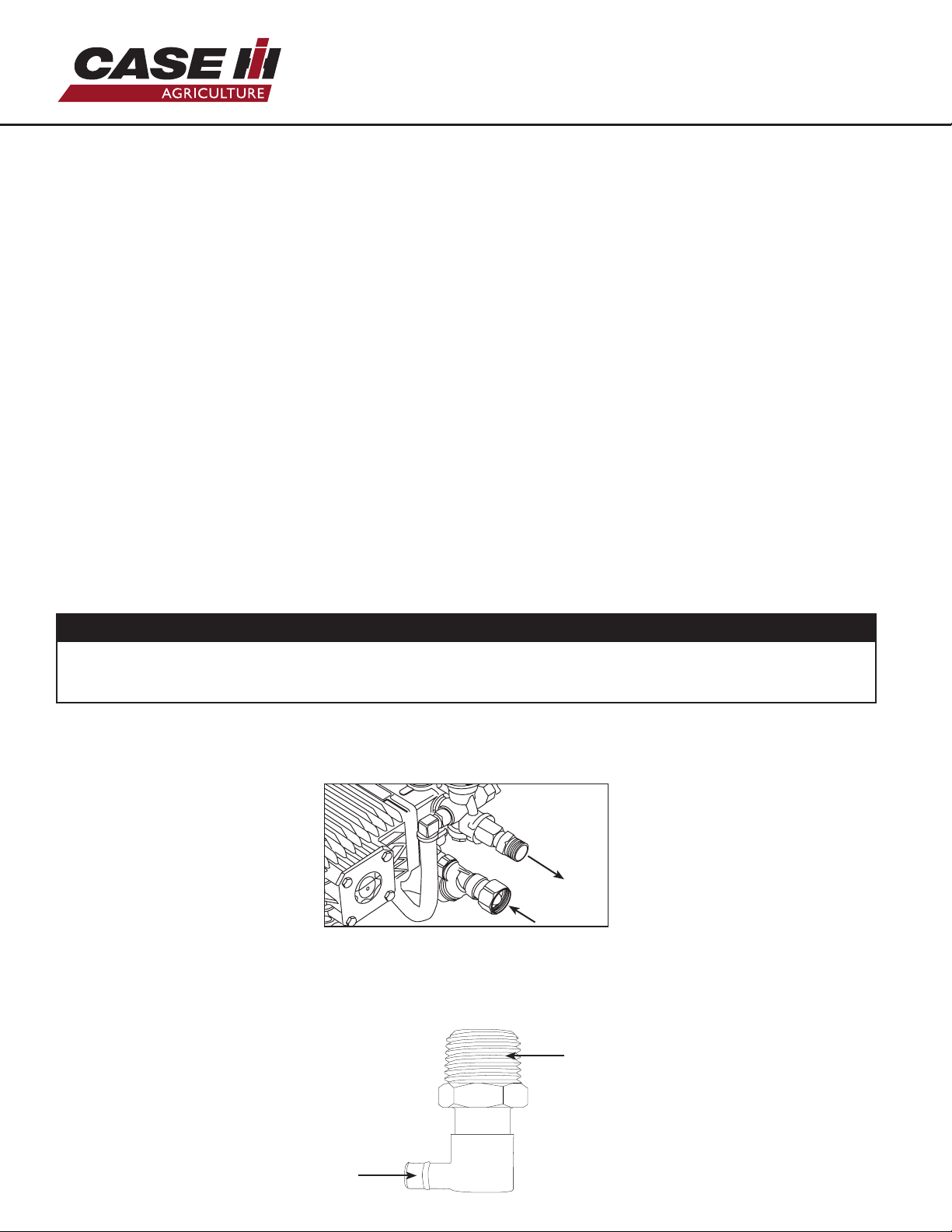
NOZZLE CONNECTION:
1. Be certain the trigger gun is locked in the “OFF” position. See WARNING, left.
2. The nozzle assembly should be disconnected from the gun/wand assembly
at this by retracting the locking ring on the quick-connect tting to remove
the nozzle.
WARNING
RISK OF INJECTION CAUSING
SEVERE INJURY!
NEVER LOOK DIRECTLY AT THE
NOZZLE ORIFICE UNLESS IT
IS DISCONNECTED FROM THE
GUN/WAND ASSEMBLY!
CONNECTION OF Q.C. NOZZLES
QUICK-CONNECT FITTING
WARNING
RISK OF SEVERE INJURY!
THE TRIGGER GUN SHOULD
ALWAYS BE LOCKED IN THE OFF
POSITION WHEN NOT IN USE!
QUICK-CONNECT (Q.C.)
0°
15°
40°
25o
GREEN

10
CONNECTING TO WATER SUPPLY
WATER SUPPLY
1. Select a water supply hose which is a quality grade of garden hose measuring at least
3/4” ID and no longer than 50 feet.
2. Check the water inlet strainer to ensure it is clean and free of any obstructions. As a
strainer becomes obstructed, it restricts the flow of water to the pump. This can result
in cavitations which will prematurely cause failure of pump components.
a. Using a screwdriver, remove the screen from the water inlet.
b. Clean or replace if necessary.
3. Connect the garden hose to the inlet of your high pressure pump. Thread the
connection together by hand until tight. Ensure the connection is tight at both ends
(at the pump inlet and at the water supply source).
4. Follow the incoming water requirements listed below:
a. Water pressure must be a minimum of 20 pounds per square Inch (PSI) and a
maximum of 125 PSI. (A typical outdoor faucet will generally supply this PSI if turned
completely “ON”.)
b. Incoming GPM (Gallons Per Minute) must be approximately one gallon more than
the outgoing GPM stated on the pressure washer nameplate. (You can check GPM by
timing how long it takes to fill a 5 gallon container).
5. Never allow the unit to operate without the incoming water line attached and the
water supply opened all the way.
NOTICE
• If there is a high mineral content in your water, it is highly recommended that a water
softener and an additional water strainer be added to the water inlet. This will help
prevent the possibility of excessive scale buildup inside the heat exchanger coil.
Pumps are water cooled. When the machine is running, ensure the trigger of the gun is
pressed to allow a constant flow of fresh water into and out of the pump. Do not let the
machine run for more than 30 seconds without pressing down on the trigger.
triplex pump
Most pumps are protected by a thermal valve. The thermal valve releases water if a
pump starts to run too hot. It will prevent catastrophic heat failure. However, the pump
may have suered damage and need maintenance, repair, or replacement. If it does not
reset and continues to leak water, the thermal valve may need to be replaced.
threaded into pump
with teflon tape
leaks water to
prevent overheating

11
INITIAL START-UP & OPERATION
START-UP AND OPERATION (COLD WATER)
To start your pressure washer for the first time, follow these instructions step-by-step.
This starting information also applies if you have let the pressure washer sit idle for at
least a day.
1. Make sure the unit is level and placed on solid ground. Ensure the wheels are locked so
that it doesn’t move during operation.
2. Connect garden hose to water inlet on pressure washer pump. To do this, thread the
end of the hose into the inlet by hand until tight and secure.
3.Attach wand extension to spray gun. Tighten by hand.
4. Choose desired spray tip, pull back nozzle extension collar, insert spray tip and release
collar. Tug on spray tip to make sure it is securely in place. See Spray Tips on page 9
for more information.
NOTICE
DO NOT run the pump without the water supply connected and turned on. Failure
to follow this rule will result in damage to the pump. Damage caused by running the
pump without water is not covered by warranty.
5. Pull down on the collar of the quick-connect coupler, slide onto the gun connector
and let go of collar. Pull on hose to ensure the connection is tight.

12
6. Attach the other end of the high pressure hose to high pressure outlet (“A” on
diagram below) on pump. Pull down on collar of quick-connect, slide onto pump and
let go of collar. Note that some pumps require the hose to be threaded on. Tug on the
hose to ensure connection is secure.
7. Turn water supply on if you have not already done so. Point the gun in a safe direction
and squeeze the trigger to purge the pump of air and debris. Do this until water flow
is no longer erratic. Continue to hold trigger of gun down while starting the machine
to ensure there is no pressure build-up.
8. Take a final look at all connections to make sure there are no leaks or loose
connections. If there are any leaks in hoses, they must be replaced.
IMPORTANT: DO NOT siphon standing water for the water supply.
*Pump Uses SAE30 Non-Detergent Mineral Oil
START-UP & OPERATION (CONT.)
A
B
triplex pump
10. To start the machine, locate the electric ignition switch on the right side of the
engine. Insert the key and turn it to the “ON” position” until the unit starts. Do not
hold the switch to the “ON” position for more than 5 seconds as this can cause
damage to the engine. Check to ensure fuel valve is in the ON position and if starting
cold, move the choke lever to the “CLOSED” position. Reference the component
diagram below for the location of these parts.
11. If desired, the unit can also be started via the recoil starter. Ensure the fuel valve is
open and the choke is applied. Then, pull on the cord until resistance is felt, and then
pull the cord briskly. Return the cord to the engine by hand. Do not let it snap back
against the machine. Once the unit is running, it is now operating as a cold water ma-
chine.
Regardless of the starting method, remember to gradually move the choke lever back
to the “open” position once the engine is running.
*Engine Uses SAE 10W30 Oil

13
HOT WATER OPERATION
& DETERGENT
Now that the unit is running, it is operating as a cold water pressure washer.
When you wish to switch to hot water, turn the burner switch to the “ON” position.
WARNING
The temperature of the water can become extremely hot during operation.
Use caution when operating the spray gun.
NOTICE
Upon initial start-up, water will begin heating up in approximately 20 seconds. It
will reach maximum temperature within 2-1/2 minutes providing that the trigger is
continuously pressed down. The burner will not fire when the trigger is released.
1. Prepare detergent solution according to label directions. Never pump acids, alkaline,
abrasive fluids or solvents through the unit. Due to the unknown and often corrosive
characteristics of many detergents commonly used in the pressure washer cleaning
industry, it is recommended to use only mild detergents with this unit.
2. Fully immerse the detergent strainer into the detergent solution.
3. To apply solution, install the black soaper nozzle to the tip of the spray gun, unlock
the gun, and squeeze the trigger. After a few moments, a detergent/water mixture
will exit the nozzle. Start spraying the lower portion of the surface being cleaned and
move up, using long overlapping strokes. Applying from the bottom up helps avoid
streaking. Allow everything to soak briefly.
Avoid working on hot surfaces or in direct sunlight to minimize the chances of the
detergent drying, which may result in damaged surfaces. Be certain to rinse a small
section at a time.
4. To rinse, lock the trigger gun in the “OFF” position. From here, securely place the
white or green spray tip in the end of the spray gun. Unlock the trigger and spray.
It will take about 30 seconds to purge all detergent from the line. For best rinsing
results, start at the top and work down.
5. Siphon a gallon of water through the low pressure detergent injection system after
each use. This prevents the possibility of corrosion or detergent residue causing
mechanical problems during the next use.
APPLYING DETERGENT
NOTICE
This feature is designed for use with mild detergents only. Since the cleaning solution travels through
the heat exchanger coil, DO NOT use corrosives as they will cause extensive damage as well as pose a
considerable safety hazard.
strainer

14
CAUTION
Be certain the hoses and spray gun are not attached to the pump during application
of pump saver or use of the blowout tool. Having a hose attached greatly reduces the
amount of water/debris removed from the pump and coil.
SHUTTING THE UNIT DOWN
1. Move the burner switch to the “OFF” position.
2. Squeeze the trigger and discharge the water for three minutes to cool the heat
exchanger and high pressure hose. Insucient cool-down periods for the high
pressure hose will cause excessive wear and eventual rupture of the hose.
3. Do not close the choke to stop the engine. Backfire or engine damage may occur.
4. Move the engine key switch to the OFF position.
5. Turn o the water supply and pull the trigger of the gun to relieve trapped pressure.
Disconnect and drain the high pressure hose, gun, and lance. Wipe the unit clean and
store in a non-freezing environment.
SHUTTING DOWN & STORAGE
STORAGE & WINTERIZING
When storing the unit for winter, it is important to ensure it is stored in the right
environment. Ensure the storage area stays above freezing during cold weather, and try
to limit the amount of dust gathered on the unit via a cover.
You will need to ensure that the fuel is drained from the engine prior to storage. For the
steps required to do this, see the engine user manual.
Once the unit has been stored and the gasoline has been drained, the last thing to do is
to winterize your pump. This can be done in one of two ways:
• “Pump Saver” Solution (P/N: 85.490.046). This is an anti-freeze solution that is used
before storing the unit. It coats to inside of the pump to ensure that any residual
water doesn’t freeze. To use BE Pump Saver, follow the instructions written on
the bottle. Water freezing in the pump will damage seals and other internal parts.
Freezing damage is not covered by warranty.
• “Pump & Coil Blowout Tool” (P/N: 59.400.000). This tool utilizes compressed air to
forcefully remove any water left in the pump. One end of the tool attaches to an air
compressor, while the other attaches to the inlet of your water pump via an adapter.
Follow the instructions on the back of the packaging to use the Pump and Coil
Blowout Tool.

15
MAINTENANCE
SPECIFIC MAINTENANCE
ENGINE: The engine instructions that accompany your unit detail specific procedures
for maintenance of the engine. Following the engine manufacturer’s recommendations
will extend the engine’s life and ensure the best possible performance.
PUMP: Change the pump oil after the first 50 hours of operation. After the initial change,
every 3 months or 250 hour intervals are recommended. If oil appears dirty or milky,
changes may be required in greater frequency. Use SAE 30 non-detergent pump oil
and fill only to the center of the oil sight glass. DO NOT overfill.
NOZZLE: Water flow through the spray nozzle will erode the orifice over time, making it
larger. This will result in a reduction of pressure. Nozzles should be replaced whenever
pressure is less than 85% of the maximum. The frequency of replacement will depend
upon such variables as mineral content in the water and number of hours the nozzle is
used. Every 3-6 months tends to be a standard interval for replacement.
BURNER AIR ADJUSTMENT: The air shutter has been factory preset for proper
operation between sea level and 2000 feet elevation at standard conditions (60°F
ambient water and air temperatures). In colder temperatures or higher altitudes, it
may be necessary to adjust the air supply to the combustion chamber. This adjustment
will maximize burner eciency and avoid inecient operation or excessive sooting
of the heat exchanger coil. A smoke spot test is recommended during any air shutter
and band adjustment. If you do not have the equipment to perform a smoke spot test,
follow the procedures listed below.
1. The machine must be running and the burner ON.
2. Loosen the Locking Screw (#3 at left) on the shutter.
3. Check for smoke from the heat exchanger exhaust. If smoke is not present, slowly
close the Air Shutter (#1 at left) by moving the dial counterclockwise to a lower
number. Continue moving the dial until smoke appears.
4. Record this setting.
5. Open Air Shutter (#1 at left) two increments. Example: If Air Shutter was set at 2,
move it to 4.
6. Slowly trigger the gun on and o. This will cause the burner to turn on and o. Look
for a smoke pu when the burner ignites.
7. Repeat steps 5 and 6 until you see a pu of smoke. Record the Air Shutter Setting.
8. The dierence between the recorded settings in steps 4 and 7 is the combustion
window. Set the dial 1/2 way between these settings.

16
PROCEDURE DAILY 3 MONTHS 6 MONTHS 9 MONTHS 12 MONTHS
Check engine oil level X
Change engine oil***** X X X X
Check water pump oil level X
Change water pump oil ** X X X X
Oil leak inspection X
Fuel leak inspection X
Water leak inspection X
Hose inspection X
Water inlet screen inspection X
Check fuel filter X X X X
Replace fuel filter X
Inspect belts X X X X
Replace high pressure nozzle*** X X X X
Inspect fuel pump filter* X
Replace fuel nozzle* X
Check burner air adjustment X X X X
Check burner electrodes* X
Test water pressure* X X X X
Test fuel pressure* X X X X
Test water temperature* X X X X
Descale coil**** X
* Must be performed by an authorized service technician.
** The pump oil must be changed after the first 50 hours of operation and then every
250 hours or 3 months, whichever comes first.
*** High pressure nozzle should be replaced whenever pressure drops to less than 85%.
**** Scale build-up will vary with mineral content in the water and amount of usage.
Descaling can range from weekly to yearly maintenance.
***** The engine oil must be changed after the first 8 hours of operation and then every
50 hours or 3 months, whichever comes first.
MAINTENANCE SCHEDULE

17
SYMPTOM PROBABLE CAUSE REMEDY
Engine will not
start Various engine problems Refer to the Engine Manual accompanying your
unit.
Unit components are frozen. Allow to thaw. If any part of the unit becomes
frozen; excessive pressure may build up in the
unit. This can cause the unit to burst, resulting
in possible serious injury to the operator or
bystanders.
No discharge
at nozzle
when trigger
mechanism is
squeezed.
Inadequate water supply. Ensure hose is 3/4” diameter and incoming water
supply is turned on. Ensure the water is turned all
the way on.
Low or
fluctuating
pressure.
Kink in water inlet hose. Remove kink.
Water inlet screen obstructed. Remove screen, clean, or replace.
Pump sucking air. (Prime
eliminated) Tighten all water intake connections Eliminate leaks
in intake line.
Incorrect nozzle installed on gun. Insert high pressure nozzle.
Obstructed or worn spray nozzle. Remove, clean or replace.
Damaged or obstructed valve
assy. on pump. Remove, clean or replace.
Pump packings worn. Replace packings.
Unloader/bypass valve not
operating correctly. Repair or replace.
Water is leaking
at safety relief
valve.
Unloader malfunction. Detect and correct unloader problem.
Pressure switch malfunction. Detect and correct pressure switch problem.
Safety relief valve is defective. Replace safety relief valve. NEVER run unit
without safety relief valve. Doing so can cause an
explosion!
Oil appears
milky or foamy. Water in oil. Change pump oil. Fill to proper level.
Oil leaking from
unit. Worn seals or o-rings. Consult customer service.
Detergent will
not siphon Detergent strainer is not
completely submerged in
detergent solution.
Check, submerge if necessary.
Detergent strainer obstructed. Inspect, clean, or replace.
Detergent hose cut, obstructed
or kinked. Inspect, clean, or replace.
Detergent adjusting knob turned
to closed position. Open adjusting knob. Refer to “Cleaning with
Detergents”.
Nozzle assembly is plugged. Clean or replace.
Water flows
back into
detergent
container.
Ball & spring in Venturi reversed,
missing, or corroded. Remove, clean, or replace.
TROUBLESHOOTING

18
Water flows
from the nozzle
when the
trigger gun is
locked in the
“OFF” position
Trigger gun is malfunctioning. Repair or replace.
Blower motor
will not run.
(Burner will not
ignite without
blower running)
Burner/Blower motor
malfunction. Repair or replace.
Belt broken or slipping on
generator. Adjust or replace as necessary.
Blower runs,
but burner will
not ignite.
Switch is not in “Burner” position. Check switch position.
Thermostat knob is OFF. Check thermostat knob position.
Out of fuel. Refuel.
Gun trigger is closed/not pressed. Press down on gun trigger.
Detergent valve is open, but
detergent hose is not completely
submerged in solution. (This
causes safety devices to shut
down burner.)
Close valve, or completely submerge clear vinyl
hose into detergent solution.
Pressure switch override. Pressure should be over 375 PSI
No voltage. Consult Service Department.
Fuel pump sucking air. Tighten all fuel intake connections. Eliminate leaks
in intake line.
Poor or improper fuel supply. Check fuel to ensure it is correct. Drain tank and
filter if necessary and refill with proper fuel.
Blower runs,
but burner will
not ignite.
Dirty or clogged fuel filter or fuel
water separator. Drain or replace as necessary.
Low fuel pump pressure. Check fuel pump pressure, adjust or replace as
necessary.
Fuel pump inoperative. Check pressure, replace if necessary.
Flexible coupler broken. Replace.
Fuel solenoid valve failure. Replace.
Dirty or clogged fuel nozzle. Replace fuel nozzle.
Improper burner air adjustment. Adjust.
Faulty ignition module. Repair or replace. Consult Customer Service.
Ignition electrodes damaged or
worn. Adjust or replace electrodes.
Consult Customer Service.
Burner runs
erratically. Water in the fuel. Drain fuel filter/water separator. Drain fuel tank,
and replace with clean fuel.
Dirty fuel filter/water separator. Replace element.
Dirty fuel nozzle. Replace.
Improper air adjustment setting. Adjust.
Fuel pump malfunctioning. Replace.
TROUBLESHOOTING

19
Blower runs,
burner ignites
but will not
heat.
Improper burner air adjustment
setting. Adjust the setting.
Scale build up in heat exchanger
coil. Consult Customer Service.
Burner
discharges
white smoke.
Low on fuel. Refuel. If white smoke persists, consult Customer
Service.
Excessive air supply. Adjust air flow.
Burner
discharges
black smoke.
Insucient air supply. Adjust to ensure air flow is sucient.
TROUBLESHOOTING
Blower runs,
burner ignites
but will not
heat.
Thermostat knob is OFF. Check thermostat knob position.
Detergent valve is open, but
detergent hose is not completely
submerged in solution. (This
causes safety devices to shut
down burner.)
Close valve, or completely submerge vinyl hose
into detergent solution.
Poor or improper fuel supply. Check fuel to ensure it is correct. Drain tank and
replace filter if necessary and refill with proper fuel.
Dirty or clogged fuel filter or fuel
water separator. Drain or replace as necessary.
Low fuel pump pressure. Check fuel pump pressure, adjust or replace if
needed.
Dirty or clogged fuel nozzle. Replace fuel nozzle.

20
4
5
6
7
9
1
10
3
8
11
16
34
29 20 25
24
23
19 28
33
2
HW4013HG BREAKDOWN
UNIT BREAKDOWN
HOUR METER
THERMOSTAT BURNER
ON
OFF
TACH / HOUR
OFF
This manual suits for next models
1
Table of contents