Case H80 User manual

;-i .:: j
i t;. -.,'.:
FHI
j A'* sfi * 5">
Operators Manual
H80 and H84
Snow Blowers
Win. Form No. 9-35302

INTRODUCTION
The Model H80, 38t' Snow Blower is de-
signed for use on Case Model 220 and 222
Compact Tractors above serial number
9646800. The Model H84, 48" Snow Blower
is furnished complete to mount on aII Model
220, 222, 442 and 444 Compact Tractors
above serial number 9646800.
This manual covers recommended operating
procedures, safety suggestions, maintenance
information, adjustments and installation in-
structions. Read this manual carefully be-
fore operating your snow blower. Your J I
Case Compact Tractor Dealer is well qual-
ified to answer any further questions you
LOOK FOR THIS SYMBOL TO
POINT OUT IMPORTANT SAFE.
TY PRECAUTIONS"
ATTACHMENT
DRIVE CLUTCH
LEVER
CHUTE
CRANK CRANK
SUPPORT
might have concerning your snow blower"
AIso, if the need should arise, his Service
Department with factory trained technicians,
genuine Case replacement parts and the
required facilities is in a position to pro-
vide proper repairs in the shortest time
possible.
The definitions "Right, Left, Front and Rear"
as used throughout this manual relate to the
tractor and snow blower when the operator
is seated facing forward in the normal op-
erating position on the tractor.
tQfE The J I Case Company reserves the
right to make improvements in de-
sign or changes in specifications at
any time without incurring any ob-
Iigation to install them on units
previously sold.
DEFLECTOR
*-__- AUGER
AUGER
HOUSING SKID SHOE
LIFT
ARM
Figure 1.
2

The principle components and controls of
the tractor and snow blower are identified
in Figure 1 with the same description used
throughout this manual. Refer to the trac-
tor Operator's Manual for identification of
all tractor controls.
The chute crank, attachment drive clutch
and lift lever controls are aII convenienilv
OPERATING CONTROLS
OPERAT ING SAF ETY SUGGESTIONS
located near the operator's position on the
tractor. The auger is placecl in motion by
pulling outward on the tractor attachment
drive clutch lever. The chute crank adjusts
the direction of snow discharge and the
deflector angle controls the distance the
snow is blown.
Read Safety Precautions Care-
fully.
o
10.
11.
12.
13.
t4.
15.
1.
2.
e
5.
6.
7.
B.
Regard your snow blower as a piece of
power equipment and be sure this is
understood by all who operate it.
Never allow children or young teen-
agers to operate the tractor and snow
blower.
Be sure you know how to stop the trac-
tor and auger at a moment's notice.
Instruct children to keep away from the
area of operation at all times.
Check the tractor and blower to make
certain both are in good operating con-
dition"
FiIl gas tank out of doors and avoid
spilling gasoline. Do not fill tank with
gasoline while smoking or while engine
is running.
Give complete and undivided attention
to the job at hand.
#
Keep the area clear of all persons,
particularly small children.
Stop engine and disengage attachment
drive clutch when tractor is unattended.
Disengage attachment drive clutch when
someone approaches.
Do not allow anyone other than the op-
erator to ride on the tractor or to be
towed behind.
Extreme caution should be exercisedun-
der slippery conditions. Reduce for-
ward speed. Install tire chains and
wheel weights to traction wheels for
added safety.
DO NOT ATTEMPT TO CLEAR AUGER
OR DISCHARGE CHUTE WHILE ENGINE
IS RUNNING.
When changing position of the deflector,
disengage the attachment drive clutch
and stop engine.
Never direct snow discharge at people
or buildings.
Disengage attachment drive clutch when
transporting.
16.

OPERATING TIPS
A
5.
1. Whenever possible, discharge snow down
wind.
Do not attempt to remove ice or hard
packed frozen snow.
Always overlap each pass slightly to as-
sure complete snow removal.
Use extreme care when freeing a frozen
or stuck auger or chute. Always turn
off the tractor first.
If tractor is equipped with Hydraulls T,iff,
operate with the lift lever in the "float"
(full forward) position. Never apply down
pressure to the snow blower. With the
hydraulic lift lever in the ?'floatrr posi-
tion, the skid shoes will remain on the
surface even though operating on uneven
terrain.
,.
3.
METHODS OF SNOW REMOVAL
Fisure 2
A definite pattern of operation is required
to thoroughly clean the snow area. This
pattern wiII avoid a second removal of snow
and avoid blowing snow in unwanted places.
Where it is possible to blow snow to right
and left, as on a long driveway, it is ad-
vantageous to start in the middle. See
Figure 2. Work from one end to the oppo-
site end blowing snow to both sides without
NO SNOW PILED ON IEFT SIDE
Figure 3
changing direction of discharge chute. If
snow can only be blown to one side of the
driveway, start on the opposite side. See
Figure 3. At the end of each pass, rotate
chute to opposite side for the return pass.
At the end of each succeeding pass, rotate
chute to opposite side to maintain direction
of throw into the same area.
TIRE CHAINS AND WHEEL WEIGHTS
The use of tire chains anC r,vheel weights,
Figure 4, is recommended for snow re-
moval operation. The extra traction re-
sulting gives the tractor operator maneu-
verability in handling heavy snow removal
jobs. These accessories are sold by your
dealer and are not included with the snow
blower.
The same wheel weights can also be attached
to the front of thetractorwhengardenplowing
or tilling by adding the Model H18 Front
Weight Bracket Kit.
For added traction on
soft ground, snow or
ice. I
I
ROTATE CEUTE TO OPPSITE
Figure 4

II
PREPARING FOR SNOW REMOVAL
Disengage the attachment drive
clutch when starting engine and
when transporting the snow
blower. Before the first snow-
fall, the area in which snow re-
moval is to take place should
be cleared of all stones, sticks,
etc., which might be picked up
by the snowblower. OBSTACLES
SUCH AS DRTVEWAY MARKERS,
WATER OR GAS SHUT OFFS,
ETC" SHOULD BE MARKED SO THEIR LO-
CATIONS UNDER THE SNOW ARE VERY
OBVIOUS.
To become familiar with the controls, op-
erate the tractor and snow blower in a clear
area before removing snow. The more
familiar you become with the snow blower,
the better results you wiil have in its use.
SNOW CONDITIONS
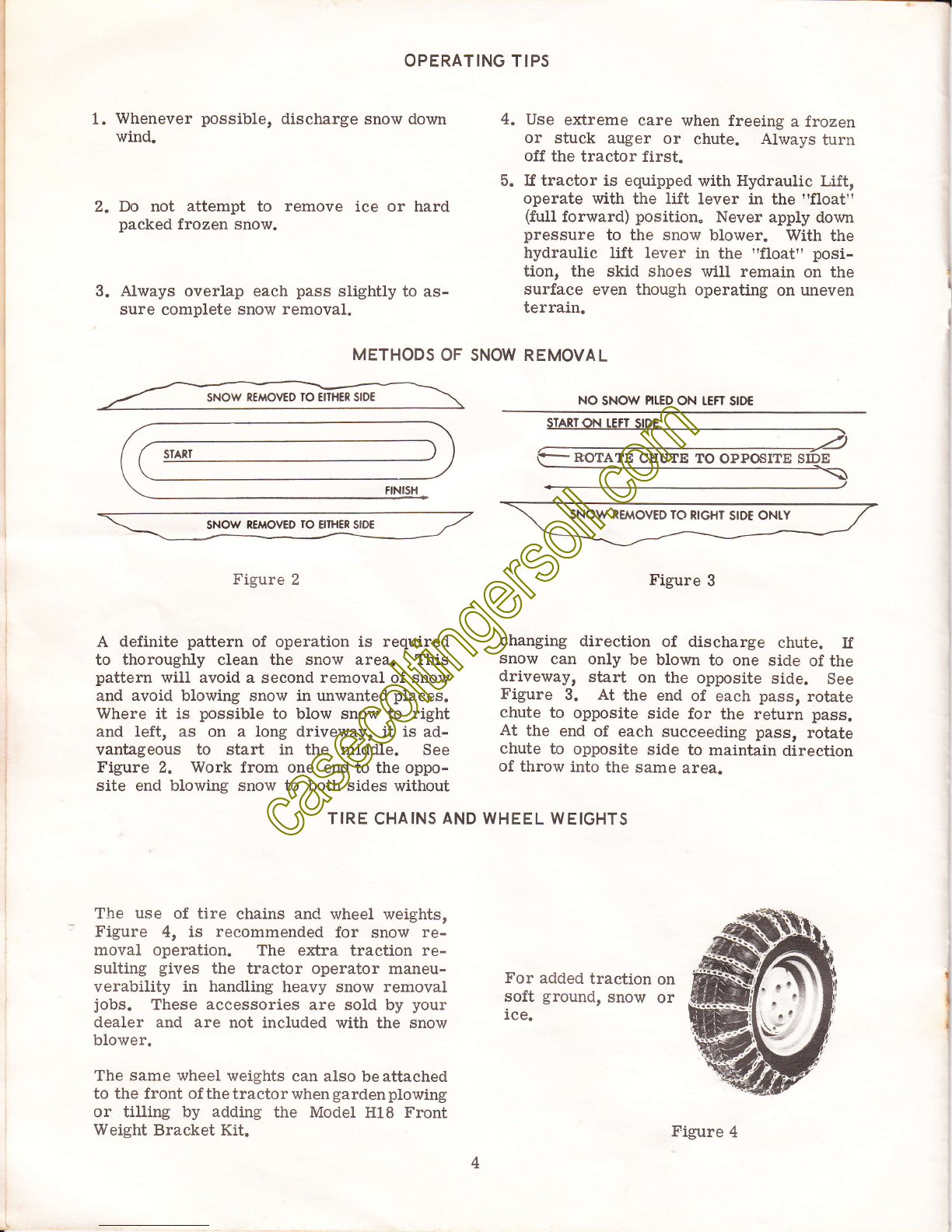
Snow removal conditions vary so greatly
from the first light fiuffy snowfall to wet
or heavy snow that operating instructions
must be flexible. The operator must op-
erate according to depth of snow, wind di-
rection, temperature, and surface conditions.
The auger speed and blowing distance are
directly related to the engine speed. For
maximum removal volume and distance,
maintain high engine RPM (three -quarters
to fuII governed throttte). Operatingatlower
throttle settings will reduce the blowing dis-
tance and increase fuel economy. Always
operate the tractor in low range for safe and
efficient snow removal. The speed control
lever should be operated to provide a ground
speed most compatible with the snow re-
moval conditions.
In extremely deep snow, raise snow blower
into transport and remove top layer first.
Lower the snow blower to the ground and
repeat process to remove the balance of
snow. Working with repeated passes into
and out of drifts will eventually move even
the deepest of snow piles.
A light coat of wax applied to the inside
surfaces of the discharge chute anddeflector
wiII help to prevent snow and slush from
sticking. The inside of chute and deflector
should be waxed several times during the
snow removal season. Use any good com-
mercial grade of paste wax or spray sili-
cone which is available from your dealer
or from your local hardware store.
Allow ample engine warm up time before
starting snow removal.
Best results are obtained when snow is re-
moved as soon as possible aJter it falls.
Check each item covered in the "ADJUST-
MENTS" and "MAINTENANCE" sections of
this manual before operating the snow blower.
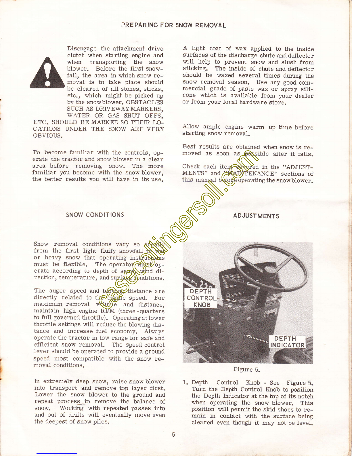
AEJUSTMENTS
Figure 5.
1. Depth Control Knob - See Figure 5.
Ttrrn the Depth Control Knob to position
the Depth Indicator at the top of its notch
when operating the snow blower. This
position will permit the skid shoes to re-
main in contact with the surface being
cleared even though it may not be level.
DEPTH
INDICATOR

AUGER DRIVE CHAIN
IDLER BOLT
ryr
D EF L ECTOR
ffi
ffi
ffiLOC KING
L EVERS
Figure 6.
2" Deflector - See Figure 6. The deflector
has a slotted hole on each side for ad-
justment. To - change the angle of the
deflector, loosen the two Iocking levers.
By angling the deflector upwardr the snow
will be cast higher and further from the
tractor. When angled downward, the de-
flector wili direct the snow closer to the
ground and it will be cast a shorter dis-
tance. Tighten the locking levers when
the deflector is adjusted to the desired
angle"
4,
'I
1...
I
/q"
3. Skid Shoes - See Figure 6. Slotted
mounting holes are provided to obtain
the oesired clearance between the base
of the auger housing and the surface of
the area to be cleared. When operating
on a smooth surface such as cement or
asphalt, the skid shoes can be set at
the lower end of the slots. ff operating
on a rough surface such as gravel or
earth, the skid shoes should be set at
the upper end of the slots to prevent
foreign material from entering and
possibly damaging the snow blower.
4" Auger Drive Chain - The chain slack at
the lower section should be held to be-
tween 3/8" and 1/2" under normal finger
pressure midway between the drive
sprockets. Adjust the idler block bolt
on the upper chain section, up or down,
as necessary to maintain proper slack.
Should the available adjustment for the
idler block be used up, the overall chain
Iength can be decreased by removing one
Iink and adding the offset link furnished
with snow blower. The idler block can
also be rotated or turned around if the
chain wears in excessively.
MAINTENANCE
Never attempt to service or make
adjustments while the snow
blower or tractor is running.
Grease the discharge chute control crank,
chute guides and the chute base ring. Figure
1, daily to keep the crank turning freely.
Once a month during season or every 25
operating hours, lubricate the auger drive
chain with Case Heavy Duty Chain and Cable
Lubricant available through your Case Com-
oact Tractor Dealer.
rc @tff;:irjrjrJJir:tJtiJr jti J:7"::irird
KEEP THE CONTACT
AREAS BETWEEN THE
CHUTE AND THE GUIDE, *
CRANK AND AUGER DIS- .-A1
CHARGE OPENING WELL :
LUBRTCATED x* -. ,
E---
Figure 7.

--rf
A LITTLE DIRT CAN CRIPPLE
CHAINS and CABLES
Check these high quality features:
. Provides constant lubri€tion, p€rmining a
smmth running chain or €ble
. Allows maimum load carrying capacrtaes on
high or low sp6ed chains.
. Reduces lrictaon drags on sudden overloads
. Preventsdripping on slow speed or idle cha,ns
. Penetrates inward-llows freely into the links
and strands.
. Serues the purpo* ol a high quality.ust pre
ventive to exmsed o( idle chains and cables
. Helps prevent cable and chain breakage and
oremature failure.
Figure B.
At the end of the snow season, the following
steps are recommended:
1. Remove the snorv blo.,ver from tractor
following the procedure outlined at the
end of this manual.
2. Wash off any salt deposit which may have
dried on the auger and chute. Paint or
cover exposed metal with a light coat of
oil. Case Touch-up Enamel is avail-
able through your Case Compact Trac-
tor Dealer.
3. Service the snow blower following lubri-
cation instructions above. Oil the auger
drive chain thoroughly using Case Chain
and cable Lubricant to prevent rust from
forming.
4" Store snow blower in a dry place.
. Giossier Than lv'iost
. Gloss Lives on Whrle Other Chalk
. Matches Original Parnl
. Exceptional Hiding Power
. Same Formula As Ongrnal
Equipment Paint
. Outstanding Package Siaortrry
CASE PAINT is Tough
Stays Glossy ls Stable
Hides Better Matches the Or grnat
Case Paint goes to Florida to roox
b€tter longer. After a pajnt sample
passes the Case weathercmeter cy-
cle, it must endure a more severe
test In sunny Flo|da In lhe sub-
troprcal regron, West ol Miamr, the
deteriorating action of high tempera-
ture, relative humrdity, annual rarn-
fall. salt atmosphere and solar raora-
tion combine to attack Case parnr
Only the best paints suryive to earn
the "Genuine" Case Lab€l
Figure 9.
INSTALLATION
A. Locate the tractor on a smooth and level
surface. Check tires for equal and rec-
ommended pressures.
t|lE The^^front tires should be inflated
to 20 nsi when the snow blower is
installld.
B. Before attaching the snow blower, lay
out the individual parts as illustrated
ir1 Figure 10. To simplify the original
installation, aII components are pre-
assembled as far as practical and the
attaching hardware is installed in its
proper location. Two drive belts are
included with the 48" Model HB4 snow
blower so it can be mounted on either
high or low clearanee tractors.
C. The following installation sequence is the
same whether the tractor is equipped
with hydraulic or mechanical lift.

F
\
.z:
::
\ ontvs
BELr(S)
Figure 1
LIFT ARM
AND CRANK
SUPPORT
SNA P
PIN
CHUTE AND
D EF L ECTOR
\
ANCHOR PIN
*MOUNTING
i ERICKET
G*
\., CHUTE GUIDES
\..
CRANK /'- \ \
0.
1See Figure 11. Position the auger assem-
bly so the tractor can be lined up with
the mounting brackets"
RolI the tractor up to the auger assem-
bly and align the anchor pins and snap
pin receptacles rvith the mountingbrack-
ets. Engage and lock the brake to hold
the tractor while attachins the snow
blower.
Slide the auger to engage the mounting
bracket notches with the anchor pins on
the tractor.
Lock the tractor snap pins in the "open"
position. Pivot the mounting bracket
upward and into the tractor snap pin
receptacles. Release the snap pins and
pivot the bracket until they are locked
as shown in Figure 12.
,-ffi
ffi
AP PIN
3.
4"
Figure 11.
AUGER

CHUTE AND
-DEFLEcToR
HEX HEAD
CRANK
SPIROL
8.
5.
9.
6.
10.
Figure 12.
Remove the safety pins fromtheliftarm.
With the plain washer located next to
the cotter pin as shown in Figure 13,
place the lift arm through the auger lift
brackets.
Iower the lift lever to align the lift
arm. Connect the lift arm to the lift
lever pin with the plain washer and
safety pin. i::stall the other safety pin
through the lift arm at the inside of the
right lift bracket.
?. Apply a coat of grease around the out-
side of the discharge spout as shown
in Figure 13.
LIFT ARM 5AF ETY
PIN
LIFT
PLAIN
WASHER
PLAIN WASHER
GREASE
DISCHARGE SPOUT
Figure 13.
Figure 14.
Apply a coat of grease to both sides of
the notched chute base ring. Place the
chute over discharge spout and engage
the base ring notches with the crank
spirol.
See Figure 14. Individualiy align thetwo
side chute guides with the square holes
in the discharge spout and secure with
round head bolts. Install the bolts with
the round head at the inside of the dis-
charge spout.
Install the front chute guide using the
hex head bolt. This bolt should be in-
stalled from the outside with the nut and
lockwasher to the inside.
lQfE Check to make certain the three
guides are square with the chute
base ring to prevent the chute from
binding when turning the crank.
BLOCK
JOINT
--'#
RANK
:&
\1
SUPPORT SPIROL ADJUSTING
BRACKET
qd:;i$,,,,,,.
SAF
PIN
ATTACHMENT
DRIVE CLUTCH
L EVER
Figure 15.

11. Thread the handle end of the crank
through the crank support and connect
the block joint to the crank spirol using
the plain washer and cotter pin pro-
vided. (See Figure 15.)
12. PuIl the attachment drive clutch lever
out to the "on" position. Raise the hood
and remove the spark plug wire as a
safety precaution. Insert the drive belt
between the fan and heat exchanger and
onto the attachment drive clutch pulley.
JA]?'l''utn, holtg are included with the
tv t 3 iti;:*"i.i H84 snow Blower to per-
mit mounting on both hi.gh and low
clearance tractors. If mounting this
snow blower on a Model 442 or 444
tractor, use the lgngq" of the two
belts. Use the shorter of the two
belts when mountlng tiris snow
blower on a Model 220 or 222 ftac-
tor.
13. See Figure 16. Place the belt under the
"fixed" idler pulieyand aroundthe "augel
shaft" pulley. Push down on the "spring
idler" pulley lever and locate the belt
on the underside. Check the belttomake
certain it is correctly installed with
the "vee" side in the vee groove pulleys
and the "flat" side in the flat groove
idler pulley.
14. Push the attachment drive clutch lever
into the "off" position and manually turn
the auger to check the belt for proper
operation. Reconnect the spark plug
wire.
ATTACHMENT
DRIVE CLUTCH -------i
F IXED
IDLER
PUL L EY
AUGER
SHAFT PULLEY
Figure 16.
15. See Figure 15. Check the operation of
chute crank. If the chute should turn
hard, check to see if the crank spirol
is binding in the chute notches. If nee-
essary, loosen the spirol adjusting
bracket bolt and shift the bracket to
relieve the bind. Tighten the bolt
following adjustment.
HP0Pfltflt Before operating the snow
blower, review and follow
the recommendations out-
Iined in the Adjustments
and Maintenance sections
of this manual.
\
SPRING
IDL ER
PUL L EY
l0
\

l
I
I
REMOVING THE SNOW
1. Disconnect spark plug wire a_s a safety
precaution, pull the attachment drive
clutch lever out to the "on" position.
2. Push the "spring idler" puiley down to
Ioosen and remove the belt. Push the
clutch lever back into the "off" position
and reconnect the spark plug wire.
REMOUNTING THE SNOW BLOWER
BLOWER
Disconnect the tift arm from the tractor
Iift lever. Remove the safety pin from
the front of the lift arm. Slide the tift
arm part way out of the auger lift brack-
ets to clear the tractor. Swing the lift
arm with crank attached over the auser
assembly.
Pull the snap pins out to release the
mountlng bracket and back the tractor
away.
:z
3. Disconnect spark plug wire as a safety
precaution. PuIl the clutcfr lever out
and install the belt as explained in para-
graph 13 of the Installation Section.
low clearance tractor belt
High clearance tractor belt
3.
A
1.
,.
With brakes locked, slide auger assembly
to position mounting bracket slots onto
the anchor pins. Pivotthe mounting brack-
et upward and engage the snap pins.
Connect lift arm to tractor lift lever and
secure with plain washers and safety pins
at both front and rear ends.
t0rE
The J I Case Company reserves the
right to make improvements in de-
sign or changes in specifications at
any time without incurring any ob-
Iigation to install them on units
previously sold.
AII of the information and instructions contained in the updated op-
erators Manual for HBO and Hg4 snow blowers g-sb3Oi R-l oatid
L0/22/71 are applicable to the J series snow blowers.
The significant change in the J series are longer drive belts to ac-
commodate installation on 1973 model tractors. Fotlowing is the drive
belt cross reference chart for interchange installationbetweenH series
and J series snow blowers.
HBO.C1649B
H84-C16499
JBO-C1B?06
J84-CtB?0?
Printed in U.S.A. 40d
11
"FJNBO

3ys.'_;!l INSTALLATION INSTRUC TION SUPPLEMENT
MoDEL HBo sNow BLowERS, s/N Fzota2 AND ABovE
H84 sNow BLowERs, s/N Gzlzol AND ABovE
4.
1.
5.
In order to reduce thesizeof theshipping
carton and hold transportation costs to a
minimum the Mounting Bracket is de-
tached from the Auger Assembly.
Position the Mounting Bracket between
the Auger Adapter P1ates as shown in
Figure 10. hsert a spacer in eachof the
Adapter Plates. Bolt the Mounting
Bracket to the Adapter Plates with the
plain washers to the outside and lock
nuts at the inside.
Three round head bolts are furnished to
attach the chute guides to the discharge
spout instead of two as shown in Figure
14. InstaII the bolts at the two side
guides with the round heads to the in-
side. For ease of assembly, install the
front guide boit with the nut and lock-
washer to the inside.
The heavy duty skid shoes can be rotated
from one side of the blower to the other
for increased life when the leading edges
wear down.
The shoes can be installed with the skids
facing either inward or outward. If the
skids are installed inward they wiII pro-
tect the cutting edge by keeping it 3/16"
higher than the skids when they are ad-
justed to the "minimum" clearance po-
sition" If the skids are installed inward
the nuts and lockwashers must be to the
inside to provide a "smooth" outside
suriace.
If the shoes are installed with the skids
to the outside they can be adjusted fur-
ther upward if desired to place the cut-
ting e$ge in direct contact with a hard
level surface such as a concrete or as-
phalt driveway. If installed in this man-
ner the nuts andlockwashers canbetothe
outside. This installation is not recom-
mended when operating on dirtrgravelor
uneven surfaces.
The replaceable cutting edge can also be
reversed for increased life when the
leading side_ wears down.
Auger Drive Chain Adjustment -- The
idler block described on page 6, para-
graph 4, has been eliminated. The two
auger mounting hubs have four holes in an
eccentric circle around the auger mount-
ing shaft. The hubs also have an ori-
entation hole near the shaft. Chainslack
at the lower section should be heldtobe-
tween 3/8" and lf 2" under normalfinger
pressure midway between the drive
sprockets.
When adjustment is necessary, remove
the two bolts from the right hand mount-
ing hub and rotate the hub in either di-
rection until correct chain tension is
obtained and reinstall the two bolts. lm-
portant - To keep the ehain in line with
the auger sprocket, rotate the left hand
mounting hub to locate the orientation
hole in the same position as the right
hand hub.
Turn the auger to make certain there is
no interference with the housing. If
interference is encountered, remove the
two bolts from the right hand mounting
hub and rotate the hub in the opposite
direction until correct tension is obtain-
ed. Reset the left hand hub to place
the orientation hole in the same location
as the right hand hub.
Should the available adjustment on
the auger mounting hubs be used
up, the overall chain length can be
decreased by removing the offset
(half) lirk from the chain.
,
il
ii
3.
t
.,j
This manual suits for next models
1
Table of contents
Other Case Snow Blower manuals