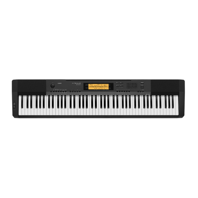
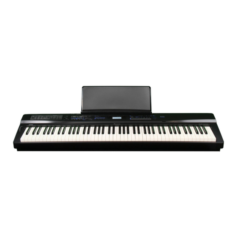
Casio Privia PX-330BK Troubleshooting guide

CONTENTS
SPECIFICATIONS..................................................................................................................... 1
BLOCK AND WIRING DIAGRAM ............................................................................................ 3
PCB LAYOUT ........................................................................................................................... 4
CIRCUIT DESCRIPTION .......................................................................................................... 5
PRINTED CIRCUIT BOARDS................................................................................................... 7
DISASSEMBLY....................................................................................................................... 13
DIAGNOSTIC PROGRAM ...................................................................................................... 42
EXPLODED VIEW................................................................................................................... 51
PARTS LIST............................................................................................................................ 53
SCHEMATIC DIAGRAMS....................................................................................................... 61

– 1 –
SPECIFICATIONS
Keyboard 88-key piano keyboard, with Touch Response (3 types)
Maximum Polyphony 128 notes
Tones 250 (with Layer and Split)
Effects Reverb (4 types), Chorus (4 types), Brilliance (–3 to 0 to 3), Acoustic Resonance
Metronome Beats per measure: 0, 2, 3, 4, 5, 6
Tempo Range: 20 to 255
Duet Adjustable tone range: 0 to 3 octaves for the left keyboard;
-4 to -1 octaves for the right keyboard
Auto Accompaniment Built-in Rhythms: 180
User Rhythms: Up to 10 (Approximately 40 KB* maximum per rhythm)
One Touch Presets: 180 types
Auto Harmonize: 12 types
Demo Songs 8 songs (tone demo songs)
User Songs Up to 10 songs (320 KB* maximum per song)
Music Presets Built-in Presets: 300
User Presets: Up to 50 (Approximately 8 KB* maximum per preset)
Registration (4 rhythm areas + 8 tone areas) × 8 banks
Recorder Functions: Real-time recording, playback
Number of Songs: 5
Number of Tracks: 17 (System Track + Tracks 01 through 16)
Capacity: Approximately 50,000 notes total (Up to approximately 10,000 notes per song)
Punch-in recording
Pedals Damper, Soft/Sostenuto (switchable)
Other Functions Transpose: ±1 octave (–12 to 00 to 12)
Tuning: A4 = 440.0 Hz ±99 cents
Octave Shift: ±2 octaves
Temperaments: 17 types
Stretch Tune
Panel Lock
MIDI 16 multi-timbre received, GM Level 1 standard
Pitch Bend Wheel Pitch Bend Range: 00 to 12 semitones
SD Memory Card SD memory card slot
Supported SD Memory Cards: Up to 2 GB
Functions:SMFplayback,lestorage,lerecall,cardformat
Inputs/Outputs PHONES jacks: Stereo mini jacks × 2
Pedal Jacks: Standard jacks × 2
MIDI OUT/IN terminals
LINE OUT R, L/MONO jacks: Standard jacks × 2
Outputimpedance:2.3KΩ
Output voltage: 1.8 V (RMS) MAX
LINE IN R, L/MONO jacks: Standard jacks × 2
Inputimpedance:9.0KΩ
Input voltage: 200 mV
Power: 12 V DC
USB port: Type B
Pedal connector (for optional SP-32 only)
– 2 –
Speakers [13cm×6cm(rectangular)]×2+φ5cm×2(Output:8.0W+8.0W)
Power Requirements ACAdaptor:AD-A12150LW
Power Consumption 12 V 18W
Dimensions 132.2(W)×28.6(D)×13.5(H)cm(521/16 × 11 1/4× 5 5/16 inch)
Weight Approximately 11.6 kg (25.6 lbs)
* Based on 1 KB = 1024 bytes, 1 MB = 10242bytes
*Specicationsanddesignsaresubjecttochangewithoutnotice.

– 3 –
BLOCK AND WIRING DIAGRAM
CN6 (3 pin)
CN11 (7 pin)
CN5
(5 pin)
CN3 (7 pin)
CN2 (16 pin)
CN601 (16 pin)
CN1 (17 pin)
CN602 (17 pin)
CN751 (8 pin)
CN7 (8 pin)
CN2 (20 pin)
CN802 (20 pin)
CN801 (12 pin) CN803 (12 pin)
CN1 (30 pin)
CN804 (30 pin)
CN801 (20 pin)
CN603 (20 pin)
CN602 (14 pin)
CN803 (14 pin) CN601 (14 pin) CN601 (12 pin) CN602 (12 pin)
CN802 (14 pin)
CN3 (14 pin)
CN201 (5 pin)
CN206 (4 pin)
CN211
CN601 (4 pin)CN501 (5 pin)
CN215 (5 pin)
CN202 (14 pin)
CN205
CN213
CN214
CN209
USB (CN9)
CN604 (5 pin)
SPEAKERS &
TWEETERS
POWER
SWITCH
MIDI
(CN216)
LINE IN L/MONO (J501)
LINE IN R (J502)
LINE OUT L/MONO (J503)
LINE OUT R (J504)
PEDAL
(J204) (J203)
PHONES
(J601, J602)
R
RT
LT
L
12 V
DC IN
(J202)
PEDAL
BUTTONS
BUTTONS
MPU
IC5
DAC
IC13
BUTTON
CONTROLLER
LSI1
LCD
LCD
CONTROLLER
LSI2
HEADPHONE
AMPLIFIER
IC201
FILTER
IC204
FILTER
IC205 POWER
AMPLIFIER
IC202
SDRAM
(256 Mbit)
IC2
SRAM (2 Mbit)
IC3
VD3
VCP
VA3
VD5
VD5
LOUT
ROUT
VA12 VA5
POWER
SUPPLY CIRCUIT
Q7, C107-C113
POWER SUPPLY
CIRCUIT
IC203, Q207, D203,
D204, C231,
C233-C237, C239
KEY CONTROLLER
IC14
MAIN PCB
(M900-MDA1)
SUB PCB
(M900-PSA1) CONSOLE PCB
(M901-LCA1)
CONSOLE PCB
(M901-CNA1)
CONSOLE PCB
(M901-CNA2)
KEYBORAD PCB (MACP-KYB1)
KEYBORAD PCB (MACP-KYD1)
PITCH
BEND
SD CARD PCB
(M810-SDA1)
KEYBORAD PCB
(MACP-KYA2)
KEYBORAD PCB
(MACP-KYB2)
KEYBORAD PCB
(MACP-KYA1)
KEYBORAD PCB
(MACP-KYC1)
KEYBORAD PCB
(MACP-KYC2)
VOLUME PCB
(M901-CNA3)
JACK PCB (M900-HPA1)
JACK PCB (M901-JKA1)
FI0-FI10, SI0-SI10, KC0-KC7
KI0-KI10,
KO0-KO-7, NC
SDD0-SD015
EA1-EA17
ED0-ED8
SDA0-SDA12, SDBA0, SDBA1
NOR FLASH MEMORY
(512 Mbit)
IC6
FCRAM
(32 Mbit)
IC7
D0-D15
A1-A23
A1-A21
D0-D15
D0-D15

– 4 –
PCB LAYOUT
PCBs Components
Main PCB M900-MDA1 MPU, Reset IC, SDRAM (256 Mbit),
Flash Memory (512 Mbit), FCRAM (32 Mbit),
SRAM (2 Mbit), Power Supply Circuit,
Key Controller, USB Port, Pitch Bend
Sub PCB M900-PSA1 DC 12 V Terminal, Power Supply Circuit, Filter, Power
Amplifer, Pedal Jacks, MIDI Jacks
Console PCBs M901-LCA1 LCD, LCD Controller, Button Controller
M901-CNA1 Buttons
M901-CNA2 Buttons
Volume PCB M901-CNA3 Main Volume
Jack PCBs M901-JKA1 LINE IN Jacks, LINE OUT Jacks
M900-HPA1 PHONES Jacks
SD Card PCB M810-SDA1 SD Card Slot
Keyboard PCBs MACP-KYA1 MACP-KYC1 Keyboard
MACP-KYA2 MACP-KYC2
MACP-KYB1 MACP-KYD1
MACP-KYB2
MACP-KYA1 MACP-KYA2 MACP-KYB1 MACP-KYB2
MACP-KYC1
M901-JKA1 M900-PSA1
M900-HPA1 M900-MDA1
M901-CNA3 M901-LCA1 M810-SDA1
M901-CNA1 M901-CNA2
MACP-KYD1 MACP-KYC2
LOWER
UPPER

– 5 –
CIRCUIT DESCRIPTION
KEY MATRIX
KC0 KC1 KC2 KC3 KC4 KC5 KC6 KC7
FI0 A0A0#B0C1C1#D1D1#E1
SI0 A0A0#B0C1C1#D1D1#E1
FI1 F1F1#G1G1#A1A1#B1C2
SI1 F1F1#G1G1#A1A1#B1C2
FI2 C2#D2D2#E2F2F2#G2G2#
SI2 C2#D2D2#E2F2F2#G2G2#
FI3 A2A2#B2C3C3#D3D3#E3
SI3 A2A2#B2C3C3#D3D3#E3
FI4 F3F3#G3G3#A3A3#B3C4
SI4 F3F3#G3G3#A3A3#B3C4
FI5 C4#D4D4#E4F4F4#G4G4#
SI5 C4#D4D4#E4F4F4#G4G4#
FI6 A4A4#B4C5C5#D5D5#E5
SI6 A4A4#B4C5C5#D5D5#E5
FI7 F5F5#G5G5#A5A5#B5C6
SI7 F5F5#G5G5#A5A5#B5C6
FI8 C6#D6D6#E6F6F6#G6G6#
SI8 C6#D6D6#E6F6F6#G6G6#
FI9 A6A6#B6C7C7#D7D7#E7
SI9 A6A6#B6C7C7#D7D7#E7
FI10 F7F7#G7G7#A7A7#B7C8
SI10 F7F7#G7G7#A7A7#B7C8
KO0 KO1 KO2 KO3 KO4 KO5 KO6 KO7
KI0 A03A0#3B03C13C1#3D13D1#3E13
KI1 F13F1#3G13G1#3A13A1#3B13C23
KI2 C2#3D23D2#3E23F23F2#3G23G2#3
KI3 A23A2#3B23C33C3#3D33D3#3E33
KI4 F33F3#3G33G3#3A33A3#3B33C43
KI5 C4#3D43D4#3E43F43F4#3G43G4#3
KI6 A43A4#3B43C53C5#3D53D5#3E53
KI7 F53F5#3G53G5#3A53A5#3B53C63
KI8 C6#3D63D6#3E63F63F6#3G63G6#3
KI9 A63A6#3B63C73C7#3D73D7#3E73
KI10 F73F7#3G73G7#3A73A7#3B73C83

– 6 –
NOMENCLATURE OF KEYS
F#3G#3 A#3 C#4 D#4 F#4G#4A#4 C#5D#5 F#5G#5 A#5
F3 G3 A3 B3 C4 D4 E4 F4 G4 A4 B4 C5 D5 E5 F5 G5 A5 B5 C6
D#3
C2 D2 E2 F2 G2 A2 B2 C3 D3 E3 B6A6G6F6E6D6 C7
C#3A#2G#2F#2D#2C#2
C1 D1 E1 F1 G1 A1 B1A0 B0
A#1A#0 G#1F#1D#1C#1 A#6G#6F#6D#6C#6
B7A7G7F7E7D7 C8
A#7G#7F#7D#7C#7
BUTTON MATRIX
KC0 KC1 KC2 KC3
KI0 INTRO/REPEAT START/STOP,
PLAY/STOP
VARIATION/FILL-IN,
FF TEMPODOWN
KI1 ACCOMP ON/OFF,
PART
NORMAL/FILL-IN,
REW TEMPO UP SYNCHRO/ENDING,
PAUSE
KI2 RECORDER POPS/JAZZ,
MUSIC PRESET
RHYTHM,
USER SONGS
BALLAD/
PIANO RHYTHMS,
RHYTHM EDITOR
KI3 LATIN/WORLD,
MUSIC PRESET METRONOME USER RHYTHMS,
RHYTHM EDITOR ―
2KC0 2KC1 2KC2 2KC3 2KC4
2KI4 GRAND PIANO
(MODERN) ORGAN ELEC PIANO BASS/GUITAR
STORE,
USB DEVICE
MODE
2KI5 STRINGS/
SYNTH-PAD
GRAND PIANO
(CLASSIC)
VARIOUS/
GM TONES VIBES/CLAVI ―
2KI6 TONE,
REGISTRATION
REVERB,
REV TYPE, EXIT
<
/ NO SPLIT,
SPLIT POINT, > ―
2KI7 CHORUS,
CHOR TYPE, < FUNCTION
CARD/INTERNAL,
SAVE/LOAD,
ENTER
>
/ YES ―

– 7 –
PRINTED CIRCUIT BOARDS
Main PCB M900-MDA1 Sub PCB M900-PSA1
Console PCB M901-LCA1

– 8 –
Console PCB M901-CNA1
Console PCB M901-CNA2
Console PCB M901-CNA3

– 9 –
Jack PCB M900-HPA1 SD Card PCB M810-SDA1Jack PCB M901-JKA1
Keyboard PCB MACP-KYA1

– 10 –
Keyboard PCB MACP-KYA2
Keyboard PCB MACP-KYB1

– 11 –
Keyboard PCB MACP-KYB2
Keyboard PCB MACP-KYC1

– 12 –
Keyboard PCB MACP-KYC2
Keyboard PCB MACP-KYD1

– 13 –
DISASSEMBLY
The photos show a prototype. The appearance of the instrument, such as color, may
differ from the actual model.
Removing the main panel
1. Undo 16 screws and remove eight L-COVERs on the bottom surface of the main unit.
2. You will see a screw inside when you remove an L-COVER. Undo and remove the screw through each
opening (eight screws in total).
NOTE: Do not drop the screws inside the main unit.
NOTE: Do not touch the hammer with the screwdriver while loosening the screws.
L-COVER

– 14 –
3. Place the main unit with the keys facing up. Undo three screws on the right side case.
4. Remove the right side case.
5. Undo three screws on the left side case.
6. Remove the left side case.
NOTE: The power switch, the M900-HPA1 PCB and the pitch bend are assembled to the left side
case. Do not pull the left side case forcibly.
7. Undo and remove two screws from each side case (S-CASE-IL and S-CASE-IR).
Left side casePitch bend
M900-HPA1 PCB Power switch
Right side case

– 15 –
8. Remove the main panel.

– 16 –
About Wiring
Whenreplacingcomponents,youmayhavetoremovecabletiesorclips.Ifyouremovecabletiesor
clips, be sure to tie cables back to the original conditions when reassembling.
<Wheretotie/bundlecables>
Power switch, M900-HPA1,
Left speaker, Left tweeter Right speaker, Right tweeter

– 17 –
Removing the main PCB (M900-MDA1)
1. Release the lock and remove two FFCs.
2. Remove four connectors.
3. Remove the pedal connector connected to the lower case.
4. Removethetapexingthepedalconnectorcableinplace.
5. Undo the screw below the USB jack on the back of the main unit.
6. UndovescrewsandthenremovethemainPCB(M900-MDA1).
Tape
FFC (Keyboard)Connector (Pitch bend)
Connector (M900-PSA1)Connector (M901-LCA1)
Connector (M810-SDA1)
Pedal connector

– 18 –
M900-PSA1 PCB
M901-JKA1 PCB
Connector
<Caution when replacing with a new part>
To attach sponge to the cable to the M900-MDA1 PCB, refer to the illustration below for its position.
<Caution when replacing with a new part>
To attach sponge to the cable to the M901-JKA1 PCB, refer to the illustration below for its position.
10 ± 5 mm
10 ± 5 mm
Removing the jack PCB (M901-JKA1)
1. Disconnect the M901-JKA1 PCB from the M900-PSA1 PCB by disengaging the connector between
them.
2. Undo two screws and then remove the M901-JKA1 PCB.
This manual suits for next models
1
Table of contents
Other Casio Electronic Keyboard manuals

Casio
Casio LK-43 User manual

Casio
Casio LK-73 User manual

Casio
Casio LK-125 Troubleshooting guide

Casio
Casio CT-X9000IN User manual

Casio
Casio SA-65 User manual

Casio
Casio Casiotone MT-600 User manual

Casio
Casio LK-160 User manual

Casio
Casio Oriental Maestro AT1 User manual

Casio
Casio WK-3800 User manual

Casio
Casio PK-5 User manual

Casio
Casio CTK-7300IN User manual

Casio
Casio Celviano AP-45 User manual

Casio
Casio Celviano AP-21 User manual

Casio
Casio CTK-530 User manual

Casio
Casio CTK-4200 User manual

Casio
Casio LK-93TV User manual

Casio
Casio MZ-2000 User manual

Casio
Casio LK-50 Parts list manual

Casio
Casio LK-300TV User manual

Casio
Casio CTK-811EX User manual