manuals.online logo
Brands
  1. Home
  2. •
  3. Brands
  4. •
  5. Roland
  6. •
  7. Electronic Keyboard
  8. •
  9. Roland Juno-6 User manual

Roland Juno-6 User manual

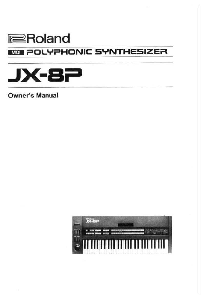
JUNO-6 ^Roland
Operation Manual
The Roland Juno-6 is asix voice and
sixty-one key polyplionic synthesizer.
•The Digitally controlled Oscillator that
offers exceptionally stable pitch.
•The real six voice polyphonic synthesizer
connpletely equipped with 6VCF's,
6VGA's and 6ENVs.
•An Arpeggio function that enables you to
enjoy wide variation of the patterns by
changing the MODE and the RANGE.
•Chorus effects that expand the sounds for
arich performance.
•Akey transpose function that allows you
to transpose to any keys.
•It is necessary for you to understand the
functions of the controls and selectors
of the Juno-6 perfectly so that you can
fully enjoy the advantages of the unit.
Some setting examples are shown in this
manual so that it might be easier for you
to master how to operate the Juno-6,
but you are the one who creates the
sounds. Please find out your own setting
and new ways of playing.
Contents
Basic Connections 5
Functions 6
I. Functions for Sound Creating ... 6
DCO .' 6
HPF 8
VCF 8
VCA 10
ENV 10
LFO 11
I. Functions, for Playing 12
Keyboard 12
Controllers 12
Arpeggio 13
Hold 14
Key Transpose 14
Remote Controls .....; 15
I. Effects 16
Chorus 16
Other Effects (Options) ....... 16
•Arpeggio Samples 17
•Sample Sounds 18
•Sound Synthesis Memo 29
•Specifications 32
•Options 33
fFunctions for Playing- >iEffect —
^
Hold this button down and
press the key to which you
want to transpose.
mmammsm
The sound remains even
after the key is released.
(This applies to Arpeggio
as well.)
Changes the pitch
ranges.
Changes the speed of
Arpeggio.
ALow Frequency Oscillator that generates vibrato and growl effects.
Digitally controlled Oscillator that determines the pitch.
It also generates three waveforms that are the sound source of the synthesizer.
Turns on and off
the Arpeggio function.
Changes the move-
ment of the patterns.
The filter that cuts or emphasizes harmonics and consequently determines the tone color.
iM The amplifier that controls the amplitude, resulting in changing the volume.
It generates the control voltage which is applied to the VGA and VCF,
controlling the harmonics and the volume.
i^ammmmmiimi
This changes the depth
of the Chorus effect.
XON/OFF
O
WiEciii©
MODE RANGE
Wiiiiis
DOWN
V^_y DOWN U3 1=
DELAY TRIG
RATE TIME MODE rtu /! ru suBOSC noise
SUB __
GOO
LFO
MAHUAL ®
FREO RES
0:
A
5
D
1
s
im—R
i
2
^
5
°-Hg B-Hi m——
H
iII
oo
^
VOLUME
\1/
DCO VCF -^/^i^/
!__. -(fUJj-
2^
—A^^A-
Pg
r1
—LFO TRIG OCTAVE
TRANSPOSE
11—
5
(#)
pNORWAL 1
DOWN UP
BENDER
O1
The manually operated button
for the LFO.
(It works when the TRIGGER
MODE switch, situated in the LFO,
is set to MANUAL.)
To alter the range
of the keyboard.
(1 octave up and down.)
Amanually operated lever which
controls the pitch of the DCO
and the Cutoff Frequency of
the VCF.
This control sets the maximum
effect of the BENDER.
This controls the rate
of the LFO. To select the pulse width
controlling signal.
This emphasizes the Cutoff
Point (creating unusual
sounds).
This selects the signal which controls the VCA.
(It decides whether to change the volume
by using Envelope signal or Gate signal. )
fe2i
(AUTO) In this mode it delays
the vibrato (growl) effects by
the set amount.
(MANUAL) While the LFO
TRIGGER button is being pressed,
the DELAY TIME determines the
time required for the LFO signal
to become maximum.
The LFO operates either manually or
automatically depending on which
position this switch is set to.
(MANUAL, AUTO)
It adjusts the depth of the
vibrato effect.
You can select the output
waveform of the DCO.
(Each of them can be
switched on and off indi-
vidually.)
This determines the polarity
of the Envelope.
(Negative polarity is for
special effect.)
This adjusts the level of the
Envelope signal which con-
trols the Cutoff Point of
the VCF.
This controls the time,
needed for the voltage
to reach its maximum
level after the key is
pressed.
This determines the time
needed for the voltage
to reach the Sustain level.
This is the volume of another
sound source, NOISE.
As you raise the knob, low fre-
quency is cut. (The sound is
getting brighter.)
This adjusts the depth of the
growl/wah effects.
As you lower the Knob, the
difference of the tone colors
between different notes
becomes larger.
(MANUAL) The pulse width is adjusted.
(LFO,ENV) The intensity of the modu-
lation is controlled.
As you lower the knob, high
frequency harmonics are cut off.
(The sound is getting softer.)
This determines the Sustain
level to which the voltage
falls at the end of the
Decay time.
This sets the time
required for the sound
to finally fades out
after the key is released.
^Functions for Playing Ji. Functions for Sound Creating- J
Basic
Conriections
TUNE
^^«
ARPEGGIO PEDAL VCF PHONES
CLOCK IN HOLD CONTROL OUTPUT
Refer to P. 15
PEDAL SWITCH FOOT VOLUME
DP-2 FV-200
Refer to P. 15 Refer to P.I 5
TUNE (±74 note)
f>
KEYBOARD AMP M/H
AUDIO AMP H
RECORDING UNIT H
P.A. MIXER L/M/H
GUITAR AMP L/M
etc.
V- J
STEREO HEADPHONES
RH-10
Adjust the volume with the
Volume control knob.
I. Functions for Sound Creating
DCO
(Digitally Controlled Oscillator)
DCO is the digitally controlled oscillator that
controls the pitch and creates three types of
waveforms which are the sound source of
the synthesizer. Compared to VCO (Voltage
Controlled Oscillator), DCO has superior
stability. The operations and functions of
the DCO are virtually the same as those of the
VCO. ADCO does not, however, provide
portament function, because of its digitally
controlled system.
BM«i
nu /I ru
SUB
oo o
SUBOSC NOISE
DDDi
nu /I nj ,WAVEFORMS
You can select the output Waveform of
the DCO. Each switch can be individually
turned on and off and can be used with
other switches.
(2) PWM MODE switch
When it is set to (MAN), pulse width can be
set with the PWM knob (3). When it is set to
LFO or ENV, pulse width is controlled by
the corresponding signal from the LFO or the
envelope generator.
(3) PWM ePulse Width Modulation
When PWM MODE switch (2) is set to (MAN),
this knob controls pulse width, and controls
the intensity of the modulation when it is set
to LFO or ENV.
SUB OSC •Sub Oscillator Level
It controls the volume of the SUB OSC.
(5) LFO •LFO MODULATION
It adjusts the depth of the vibrato effect
when the LFO is controlling the pitch of the
DCO.
(6) NOISE eNOISE level
It controls the volume of the NOISE.
<Pulse Wave>
When the top and bottom portions of the
square wave are unequal, the result is what is
called apulse wave. The harmonic content of
the pulse wave will depend greatly on the
width of the pulses. It is possible to modulate,
or change the pulse width by means of the
LFO or the envelope generator.
7
Waveform
Setting
®
m®
PWM
Waveform
N
Saw Tooth
Square
Pulse
Description
The sawtooth wave contains
afundamental sine wave and
its integral harmonic sine
waves at afixed ratio. The
level of each harmonic is as
shown on the right. When
fundamental content is 1,
the content of «th harmonic
is 1/n.
The square wave contains a
fundamental sine wave and
its odd numbered harmonics
at afixed ratio. The level of
each harmonic is the same as
sawtooth wave; the content
of nth harmonic is 1/«;
except that there are no even
numbered harmonics.
With pulse wave, the har-
monic content greatly varies
depending on the pulse
width. It is characterized by
alack of the nth harmonic
series when the pulse width
is 1/«. The example on the
left lacks 3rd, 6th, and 9th
harmonics because the pulse
width is 1/3 (33%).
Harmonic Content
F2 3 4567
nra
357
PULSE WIDTH
at 33% (1/3)
nn
F2457
Square wave one octave lower than the DCO's (||J )
Pulse Width ^Manual PWM
PWM MODE SWITCH Q) ^MAN
PU LSE Wl DTH (3) ^Determins the Pulse width.
50%-"
PWMby LFO
PULSE MODE SWITCH (g) ^LFO
PULSE WIDTH MODULATION (3) >
Adjusts the intensity of nnodulation. LFO
SIGNAL
OUTPUT
WAVE-
FORM
PWM by ENV
PWM MODE SWITCH @^ENV
PULSE WIDTH MODULAT ION (S) ^
Adjusts the intensity of modulation. ^^^
SIGNAL
WAVE-
FORM
rrLonoomin =
8
HPF
(High Pass Filter)
This filter lets the high frequency harmonics
pass and cuts off the low frequency harmo-
nics. As this filter is not voltage controlled.
Cutoff Point is changed by only moving the
knob.
FREQ •Cutoff Frequency
Cutoff Point of HPF can be adjusted with
this knob. As you raise this knob, frequencies
in the low pitch range will be cut off.
VCF
(Voltage Controlled Filter)
This filter changes the tone color by cutting
off or emphasizing harmonics. This filter lets
the low frequency harmonics pass and cuts off
the high frequency harmonics, and is con-
trolled by avoltage.
@FREQ •Cutoff Frequency
This knob is to change the Cutoff Point of the
VCF. As you lower the knob, the frequency
in the high pitch range will be cut off, and the
sound will fade out when the waveform be-
comes nearest to aSine Wave.
^C^^ •> Refer to P. 15
(^ RES •Resonance
This control emphasizes the Cutoff Point set
by Cutoff FREQUENCY knob @. As you
raise the knob, certain harmonics are em-
phasized and the created sound will become
more unusual more electronic in nature. If
you alter the Cutoff FREQUENCY knob
while the RESONANCE is set to ahigh level,
you can create atype of sound that is attain-
able only from asynthesizer. If you raise
the RESONANCE up to the maximum, VCF
will start Self Oscillation.
(5) ENV •Envelope Modulation
When the Cutoff Point of the VCF is being
modulated by the output of the Envelope
Generator, this knob is used to adjust the
intensity of the modulation. You can change
the Cutoff Point of the VCF in each note with
the ADSR pattern previously set. So the
tone color of one note can be changed quite
drastically.
(D Polarity Switch
This is the selector switch for the polarity
of the Envelope. When it is set at reverse
polarity, the ADSR pattern will be reversed
and the tone color alteration will be the other
way round.
*NOTE
This often means the Cutoff Frequency of
the VCF (HPF) will need to be set higher.
(6) LFO •LFO Modulation
When the Cutoff Point of the VCF is being
modulated by the output CV of the LFO,
this knob adjusts the depth of the growl or
wah effects.
(D KYBD •Key follow
When the Cutoff Point is being controlled
by the KYBD-CV (Keyboard control voltage),
this knob adjusts the level of the KYBD-CV.
It prevents any inconsistency in the harmonic
content caused by pitch alteration. Conse-
quently this knob is usually set to the maxi-
mum on such along keyboard, but can be set
to your taste.
*NOTE
Self oscillation of the VCF does not guarantee
accurate pitch. So, you cannot obtain correct
scale when playing the Keyboard.
9
Cutoff Frequency
Resonance
ENV Modulation
Level (dB)
I
/v^
Level (dB)
\ArJ /VvJ IAa
i
fVlM
Level (dB) t
JIaJ
(Vw,
/W^ l/lA'
i
1
PPositive Polarity Voltage (V)
yNegative Polarity
Voltage (V)
Frequency (Hz)
Frequency (Hz) \
1A
Frequency (Hz) \
Frequency (Hz)
NOTE
When modulating the VCF using the Enve-
lope, set the knob (2) to afairly low level in
case of positive porality, and set it to afairly
high level in case of negative. Otherv\/ise there
will be little effect.
10
VGA
(Voltage Controlled Amplifier)
This is to control the volume (amplitude) of
the sound, and is normally controlled by the
output voltage from the Envelope Generator.
(?) Select switch for the control signal
This switch enables you to select whether to
control the VGA by the signal from the
Envelope Generator or by the Gate signal.
ENV
(Envelope Generator)
This generates the Control Voltage applied to
the VCF and the VGA, thereby controlling
the volume and the tone color of each note.
This output voltage is generated whenever you
press akey.
®
@A{Attack time)
This sets the time required for the voltage
to reach its maximum from the moment the
key is pressed down.
(3) D(Decay time)
This determines the time required for the
voltage to drop from the maximum to the
sustain level. When the sustain level is high,
the Envelope curve does not change by
adjusting the Decay Time.
S(Sustain level)
This knob determines the Sustain Level to
which the voltage falls at the end of the Decay
Time.
(5) R(Release time)
This sets the time needed for the voltage to
reach zero.
!ENV OUTPUT
(ADSR)
iKYBO
GATE
OFF
11
The variation of eacli knob.
Attack Time
Setting of ADSR and Envelope Curve.
II I
Time (sec)-L-
Decay Time and Release Time
Time (sec)
Sustain Level
4t fi
Voltage
*In the figure shown above, the positions of
the knobs are not meant to be exactly correct,
so the knob position does not necessarily cor-
respond with the time and the voltage.
** When all of the ADSR sliders are set at
"0", the waveform will be an extremely
short Pulse wave, and only ashort "click"
is heard. Please be careful.
LFO
(Low Frequency Oscillator)
This oscillator operates only at aLow Fre-
quency. It controls the VCO and the VCF to
produce vibrato and growl effects.
DELAY TRIG
RATE TIME MODE
®RATE
This adjusts the rate of LFO.
(7) TRIG MODE •Trigger mode switch
You can select whether to operate the LFO
manually or automatically.
(8) DELAY TIME
This sets the time needed for the LFO to start
to function. The function varies depending
on the position of the TRIGGER MODE
switch (2).
®®
TRIG MODE
DELAY TIME
AUTO
m\AUTO
MAN
;man
MANUAL
LFO always functions. The LFO works while the
LFO TRIGGER button is
being pressed and stops when
the button is released.
=r =3 Other than
The LFO does not start to
function until the Delay Time
set with the DELAY TIME
has passed. (*)
While the TRIGGER button
is being pressed, the LFO
amplitude becomes larger.
When the delay time set pre-
viously has passed, it becomes
normal amplitude.
This Delay function works only in non-
legato manner. So the Delay Time affects
only the first key in alegato section.
I. Functions for Playing 12
KEYBOARD The Roland Juno-6 has 5octaves and 61 keys,
but can be played as a7octave keyboard (as
shown below) by using the TRANSPOSE
switch. When the TRANSPOSE switch is
set to Normal, the third Cfrom the bottom
corresponds to the Middle Cof apiano key-
board. So, if you wish to use the Juno-6
with the other keyboards, this knowledge
will help you to align the Middle Cof the
two keyboards.
T
Sval
5in
Iii
Transpose UP
Transpose NORMAL
Transpose DOWN |
Piano
Keyboard
Middle C
\
The Keyboard of
the Juno-6
CONTROLLERS
^
-®
©VOLUME
(2) OCTAVE TRANSPOSE
This is to transpose the scale one octave up
or one octave down.
(3) LFOTRIG
The LFO MODULATION can be turned on
and off with this button, if the LFO TRIG-
GER MODE switch is at (MANUAL) posi-
tion. (Refer to P.11)
®BEND
ADCO
When the Pitch of the DCO is being controlled
with the @BENDER, this knob adjusts the
variable range of the pitch.
AVCF
When the Cutoff Point of the VCF is being
controlled with the BENDER, this knob
adjusts the variable range of the tone altera-
tion.
®BENDER
ARPEGGIO 13
The Juno-6 allows you automatic arpeggio
play with the range of up to 3octaves.
*Arpeggio Sample -^ P.17
i«RRBGGIi3^
ON/OFF MODE RANGE
@®
®MODE
This controls the nnovement of the patterns.
(2) RANGE
This determines the pitch range of Arpeggio.
(3) RATE
This sets the speed of Arpeggio.
^njl( EXT CLOCK) ^Refer to P.I 5
AYou can enjoy wide variation of Arpeggio
by combining those three controls.
ON/OFF eArpeggio switch
^NOTE
*An Arpeggio can only play while the keys
are being held down unless the HOLD
button is pressed.
*Press each key of the chord at precise-
ly the same moment, or the first pattern
of the Arpeggio will be imperfect.
*The pitch range of the Arpeggio must be
within the keyboard range. So if you set
the range to 2or 3octaves and the Ar-
peggio pitch range exceeds the keyboard's
range, the highest pitch range will be re-
peated.
*If you turn on the Arpeggio switch while
holding the keys down, Arpeggio may fail
to start properly. Turn on the Arpeggio
switch before pressing the keys down.
RANGE, MODE Arpeggio Patterns in case of
RANGE
MODE
UP
UP/ *
/DOWN
**
DOWN
loot
i
—'tfy gl J-'
V]v ^^
Jj^Jj
2oct
I"a^—;—t~'g'^
aczt
V;
3oct
jfT \i^
m
Occasionally, the first octave may take a
while to "settle in" if you use the DOWN
mode.
Also, in the Down mode, if you change
from either of the other two modes, the
last note of the previous mode will become
the first note of the Down mode.
14
HOLD
D
When this button is pressed, the sound re-
mains even after you release the l<ey. The level
of the sound is controlled by the S(Sustain
Level) in the Envelope Generator. Con-
sequently you cannot hold asound that has
aSUSTAIN level of zero.
Also, the HOLD function applies up to 6keys
at atime, and if more than 6keys have been
played, the last six keys will remain.
^^m -Refer to P.I
5
ARPEGGIO &HOLD If you press the HOLD button while an
Arpeggio is being played, it will continue to
be played even after the keys are released. In
this case, no matter how many keys are
pressed, each time you press anew key, you
will hear anew Arpeggio with adifferent
pattern.
^NOTE
Turn the ARPEGGIO switch on before turn-
ing on the HOLD switch. If you turn on or
off the ARPEGGIO switch with the HOLD
on, the previous pattern may be played,
which makes operation awkward.
KEY TRANSPOSE
D
How to transpose
While holding the TRANSPOSE button down,
press any key in any octave. If the indicator
above lights up, transposition is completed
and the Juno-6 will now play in the key of
the chosen note.
*Normally Ccannot be transposed, only the
highest Ccan be transposed one octave up.
(The indicator lights up.)
Transposition to any key is possible. By using
the appropriate key, you can shift the pitch
of the entire keyboard. Moreover you can
play apiece with many #s and bs in the key
of Cmajor (A minor).
BHow to return to the normal key
<C key)
While holding the TRANSPOSE button down,
press any Cnote (except for the highest C),
and the indicator will go out and the Juno-6
has returned to the normal condition (the
key of C).
^Key transposition is not possible while an
Arpeggio is being played.
HOLD &KEY
TRANSPOSE
The sound, sustained" by the HOLD function,
can be transposed as well. Hold the chord
then transpose as shown above. Using the top
octave, you can transpose the key up by one
octave.
15
REMOTE CONTROLS ARPEGGIO
CLOCK IN PEDAL
HOLD VCF
CONTROL
*Connect to
OUTPUT A-.
eg. FV-200
Press it down, and the
Cutoff Frequency will rise.
^Keep the Hold switch
(on the panel) off.
Press it down, and the
Hold will be on.
OFF.
ml Release it, and the
^^ Hold will be off.
1note per
1pulse RHYTHM MACHINE
SEQUENCER etc.
^When it is connected to
the ARPEGGIO CLOCK
IN, the Arpeggio Rate
knob on the panel does
not function.
CR-8000s5000 TRIGGER OUT
DR-55 DBSsCSQ*
TR-606.808 TRIGGER OUT'
TB-303 I^,^—^,,— .
GATE OUT
CSQ-600 J
MC-4 GATE OUT'
MPXOUT"
*You can play Arpeggio with
many i<inds of patterns.
III. Effects
CHORUS CHORUS
16
This gives spaciousness and richness to the
sound. The effect becomes stronger from left
to right, that is, Mis stronger than 1.
Use the stereo output {2ch) to obtain the best
effect.
Optional Effect Units An echo chamber is most commonly used of
all the effect units. It has such astrong effect
that it is often said to be indispensable when
using synthesizers.
Effect units such as aPhaser or aFlanger have
the ability to add unique changes to the
sound, and it is effective to use them with
Echo Chamber. APhaser gives an effect
which can change the noise to ajet sound. A
Flanger has an effect similar to aPhaser's, but
stronger, and can give power to asynthesizer
bass sound.
Echo Chamber
>?^c lisJ", n»«SiT%. jB 5^,^ SRE-555
RE-501
RE-201
RE-150
Delay Machine DD30
DM-100
Digital Delay SDE-2000
Phaser/Flanger SPH-323, PH-IR
SBF-325, BF-2
Equalizer SEQ-331,SEQ-315
GE-10, GE-7
Reverb RX-100
Chorus CE-2, CE-3
SDD-320
.^eggio
Samples 17
When using Arpeggio as an accompaniment, adopt
apattem that is completed within one measure.
Select the appropriate range and -mode according to
the number of notes in the chord, and beats in the
bar.
^The SAMPLE SCORES show the examples of
when you press each note of the chord simul-
taneously-. If there is atime gap in pressing each
note, the scores will not be the same.
EThree note Arpeggio (1 oct. UP/DOWN)
OCT
3OCT DOWN
[HThree note Arpeggio (2 oct. UP)
1OCT UP
3OCT DOWN 5^
HThree note Arpeggio (3 oct. UP/DOWN)
OCT UP
:i OCT DOWN
aFour note Arpeggio (1 oct. UP/DOWN)
OCT UP
;) OCT DOWN
[D Four note Arpeggio (2 oct. UP)
1OCT UP
3OCT DOWN ^->ffj#g^
[6! Five note Arpeggio (1 oct. UP/DOWN)
IOCT UP
OCT DOWN ^p-»^^^
HArpeggio with aBass note (1
)
ePress one Bass note with the left hand and three notes of
the chord with the right hand.
OCT UP
UE^
3OCT DOWN wwm
^
mArpeggio with aBass note (2)
•Press one Bass note with the left hand and three notes
of the chord with the right hand.
1OCT UP
2OCT
3OCT DOWN m~^
dSpecial use of Arpeggio Mode (Bass Pattern
;
1OCT
3OCT DOWN 5S|^^l^0
MSpecial use of Arpeggio Mode
(Trennolo 1, II)
Tremolo I
•Play asingle note and adjust the speed of tremolo with
the RATE control.
Lower the Sustain Level and shorten the Decay Time.
Organ like sound is obtained by adjusting ENV.
1OCT UP
fS^f^^jUfUppfl^ftfiflfi
3OCT DOWN
Tremolo II
•Tremolo with xylophone like octave sound.
IOCT UP
-J OCT DOWN \g
HMBMmzzj
te
Sooiids 18
(About the Example
patches) The position of each knob in the diagrann is
not nneant to be exact, and^ the sound can
differ drastically with any slight change of the
knob positions. It also varies depending on
the type of the speaker and the amplifier
connected to the Juno-6. Please adjust the
settings while actually playing.
Also, set the CHORUS button to the level you
prefer while listening to the sound.
*The "missing" knobs in the diagrams are
irrelevant to the sound, and can be set to
any position.
3^
tWhen you get confused with operations or no sound comes out,
return to this basic setting and start again.
"1] GROUP
STRINGS
The sound of asmall group of strings. Adjust can get avibrato effect by raising the LFO
the FREQ and ENV in the VCF. Also, you knob in the DCO.
CMD
[2] GROUP
STRINGS The sound of amedium group of strings. Turn
on the SUB in the DCO and set the FREQ in
the HPF to '0', and the sound of alarge group
of strings is obtainable. Set the Chorus as you
like.
CMD
[3] ORCHESTRAL amild ensemble sound. Adjust the FREQ in brato effect can be obtained by setting the
STRINGS ^^^ V^f^ 3nd A(ATTACK) in the ENV. Vi- LFO in the DCO fairly high.
19
[4] JAZZ ORGAN With the ADSR controls all at '0', control
the VCF so that akey click sound will be
generated. By turning on the CHRUS II at
the same time, you can obtain an effect
similar to arevolving speaker (FAST).
Or 18i-®Da i19 DBD
[5] CHURCH
ORGAN Athick, church organ like sound. The tone
color widely varies depending on the position
of the FREQ in the VCF.
^§rBBSi DBD
[6] HOME ORGAN The sound of Electric Organ for home use.
You can adjust the vibrato effect (the LFO in
the DCO or the RATE in the LFO) according
to your taste. The tone color can be greatly
altered by changing the FREQ control in the
VCF.
[7] SINE-WAVE The sound source is the sawtooth wave. If
ORGAN ^°^ adjust the FREQ in the VCF to the
fundamental pitch and set the RES high, you
can obtain apure sine wave, as only the
fundamental content is being passed. This
method should be adopted when accuracy
is required, while the sine wave is also obtain-
able by sending the VCF to self oscillation.
as
20
[8] SQUARE-WAVE The sound source is the square wave of the
Sub Oscillator. Set the TRANSPOSE to UP.
Adding the CHORUS effect might be inter-
esting.
[9] STEAM ORGAN The Self Oscillation of the VCF is used as a
sound source as well as the Square Wave of
the DCO. Set the FREQ in the VCF to '0'
and turn it up alittle by little while pressing
the note C. You will hear the sound of the
DCO (note C) first, and then the sound by
the VCF Self Oscillation will be joined. So
adjust the FREQ of the oscillating VCF
until it is an octave and a5th higher than
the DCO.
CMD 10:
10] ELECTRIC
PIANO I
Adjust the Dand Rin the ENV as you like.
By setting the FREQ in the HPF to '0' and
turning the CHORUS II on, you can get a
Honky Tonk like sound.
[ir ELECTRIC
PIANO II
This sound contains very few high harmonics.
Like [7] ,adjust the FREQ in the VCF so
that only the fundamental can pass. Adjust
the Decay Time and the Release Time in the
ENV according to your preference.
la Or030 i
21
[12] HARPSICHORD abrighter sound can be obtained by cutting The tone color changes drastically if you
the Low Frequencies using the HPF alter the PWM in the DCO.
m
[13] CLAVI Rennember to set the TRANSPOSE switch to
DOWN. The tone color can be changed
widely by using the FRED in the VCF. Set-
ting the ENV in the VCF slightly higher
might be effective.
=r LJ*" 8i-®DDi
[14] GUITAR The tone color changes according to the created by setting the PWM MODE SWITCH
FREQ in the VCF. Unique sounds can be in the DCO to ENV. Adjust the RES as well.
[15] SYNTHESIZER
HARP This tone color is suitable for playing
Arpeggios. Adjust the FREQ in the VCF and
the Rin the ENV as you like.
Oil)
,J Ti.

Other manuals for Juno-6

1

Other Roland Electronic Keyboard manuals

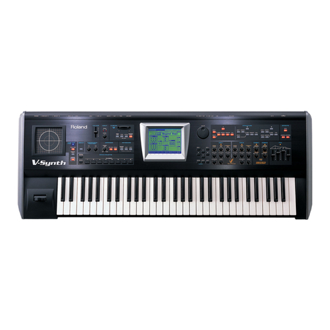
Roland V-Synth User manual

Roland

Roland V-Synth User manual

Roland E-300 User manual

Roland

Roland E-300 User manual

Roland Fantom G6 Specification sheet

Roland

Roland Fantom G6 Specification sheet

Roland BK-5 User manual

Roland

Roland BK-5 User manual

Roland KR-115 Manual

Roland

Roland KR-115 Manual

Roland V-Combo VR-09 User manual

Roland

Roland V-Combo VR-09 User manual

Roland MUSIC ATELIER Series User manual

Roland

Roland MUSIC ATELIER Series User manual

Roland AT15 Music Atelier User manual

Roland

Roland AT15 Music Atelier User manual

Roland RD-700GX User manual

Roland

Roland RD-700GX User manual

Roland A-90 Technical manual

Roland

Roland A-90 Technical manual

Roland VA-76 User manual

Roland

Roland VA-76 User manual

Roland A-90 User manual

Roland

Roland A-90 User manual

Roland FANTOM-06 User manual

Roland

Roland FANTOM-06 User manual

Roland RS-101 Strings Quick start guide

Roland

Roland RS-101 Strings Quick start guide

Roland Fantom-Xa Specification sheet

Roland

Roland Fantom-Xa Specification sheet

Roland E-X10 User manual

Roland

Roland E-X10 User manual

Roland Edirol PCR-80 Instruction Manual

Roland

Roland Edirol PCR-80 Instruction Manual

Roland Interactive Arranger EXR-46 OR User manual

Roland

Roland Interactive Arranger EXR-46 OR User manual

Roland Fantom-G none Instruction manual

Roland

Roland Fantom-G none Instruction manual

Roland A-70 User manual

Roland

Roland A-70 User manual

Roland DJ-70 User manual

Roland

Roland DJ-70 User manual

Roland Fantom G8 User manual

Roland

Roland Fantom G8 User manual

Roland JX-3P Operating and maintenance manual

Roland

Roland JX-3P Operating and maintenance manual

Roland V-Synth GT Assembly instructions

Roland

Roland V-Synth GT Assembly instructions

Popular Electronic Keyboard manuals by other brands

Casio Privia PX-110 user guide

Casio

Casio Privia PX-110 user guide

Yamaha PortaSound PSS-390 owner's manual

Yamaha

Yamaha PortaSound PSS-390 owner's manual

Casio LK-30 user guide

Casio

Casio LK-30 user guide

Peavey Spectrum Bass user guide

Peavey

Peavey Spectrum Bass user guide

Yamaha F01 Quick operation guide

Yamaha

Yamaha F01 Quick operation guide

Fatar ST-610 user manual

Fatar

Fatar ST-610 user manual

Casio Privia PX-700 Service manual

Casio

Casio Privia PX-700 Service manual

Casio CTK-531 user guide

Casio

Casio CTK-531 user guide

M-Audio KeyStudio user guide

M-Audio

M-Audio KeyStudio user guide

Hammond XLK-5 owner's manual

Hammond

Hammond XLK-5 owner's manual

Keith McMillen Instruments QuNexus Reference manual

Keith McMillen Instruments

Keith McMillen Instruments QuNexus Reference manual

Yamaha NP-30 owner's manual

Yamaha

Yamaha NP-30 owner's manual

Casio Privia PX-110 Function guide

Casio

Casio Privia PX-110 Function guide

Casio CTK-480 Operation manual

Casio

Casio CTK-480 Operation manual

Yamaha PortaTone PSR-1000 Data list

Yamaha

Yamaha PortaTone PSR-1000 Data list

Casio CDP-200R Service manual & parts list

Casio

Casio CDP-200R Service manual & parts list

NexxTech 61-Key Electronic Keyboard instruction manual

NexxTech

NexxTech 61-Key Electronic Keyboard instruction manual

Yamaha Portatone PSR-175 Manual de instrucciones

Yamaha

Yamaha Portatone PSR-175 Manual de instrucciones

manuals.online logo
manuals.online logoBrands
  • About & Mission
  • Contact us
  • Privacy Policy
  • Terms and Conditions

Copyright 2025 Manuals.Online. All Rights Reserved.