— 4 —
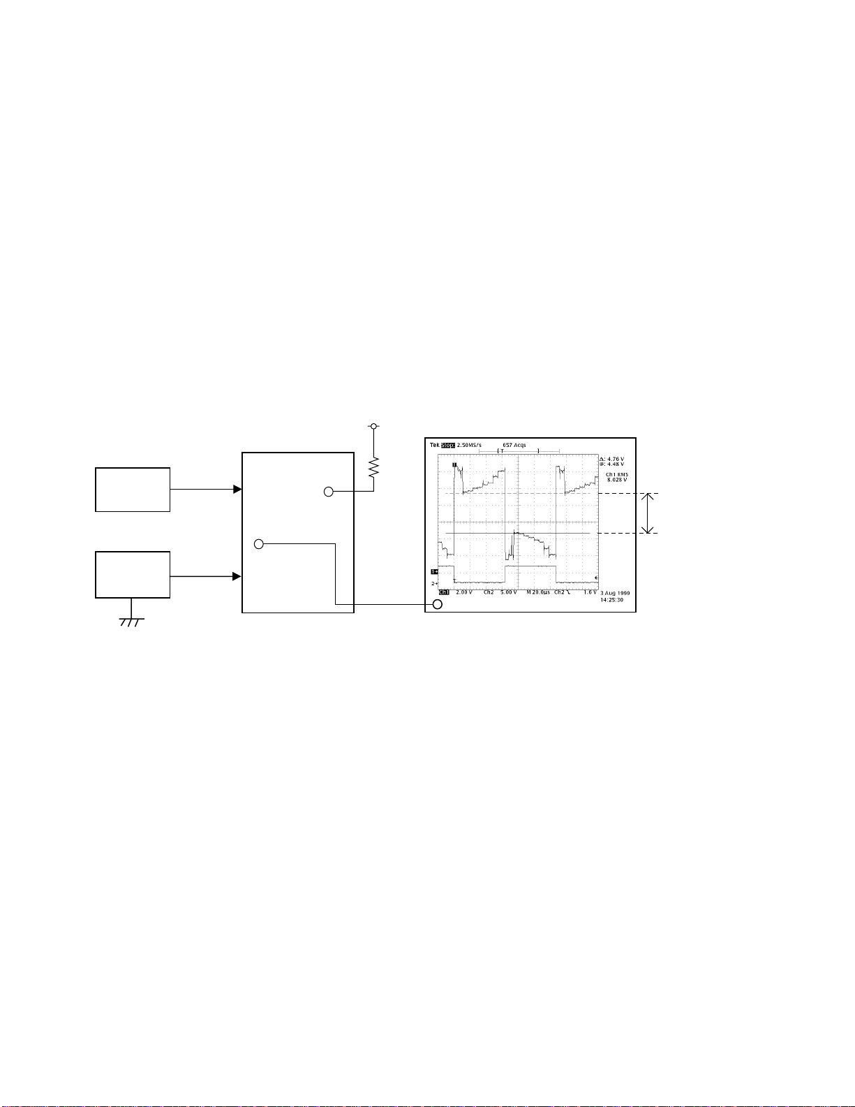
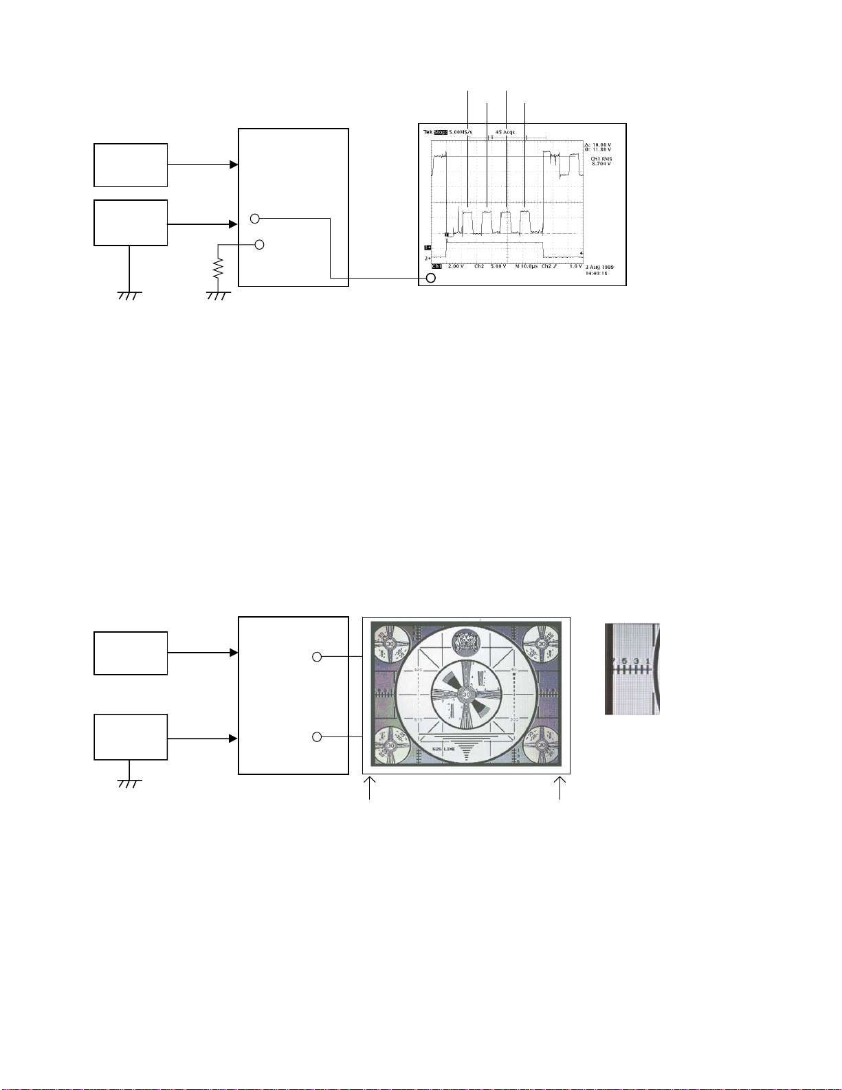
4. TINT color adjustment
•Conditions
(1) Apply 11.50 ±0.05 [V] on Vcc1-1.
(2) Signals: provide color bar pattern (white 75 %) composite video signal from CP196.
Signal level; 1Vp-p +/- 0.01V (75 ohm termination), conforming to NTSC-M system.
(3) Connect 47kohm resistor between CP304 and CP300 (GND).
•Adjustment
(1) Triggering CP702 (FRP), observe CP706 (VB) waveform.
(2) Adjust VR303 so that yellow, green, and red pulses are level.
(3) Adjust VR302 so that yellow, green, and red pulses are same height as black pulse.
(4) Repeat steps (3) and (4) until;
Amplitude difference of blue and purple pulses (center two pulses) is less than 0.1V.
Amplitude difference between black and yellow and red (both adjoining pulses of blue and purple) is less
than 0.1V.
(5) Remove the 47kohm resistor between CP304 and CP300 (GND).
VCC1-1
IF signal
Signal
generator
Stabilizer
M-PCB
CP706
CP304
Yellow Black
Green
Red
47 KΩOscilloscope
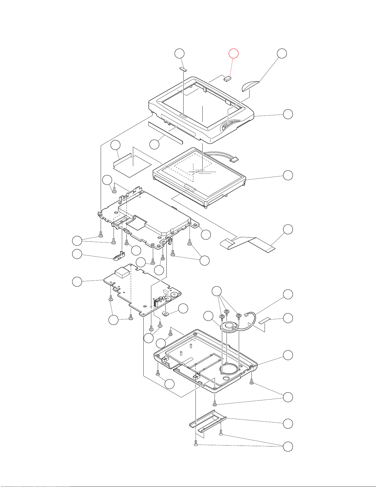
5. LCM screen positioning
•Conditions
(1) Apply 11.50 ±0.05 [V] on Vcc1-1.
(2 Signals: Apply monoscope pattern composite video signal from CP196.
Signal level; 1Vp-p +/-0.01V (75 ohm terminated), conform to NTSC-M system.
•Adjustment
(1) Connect LCM to display monoscope pattern.
(2) Adjust LCD’s H.POS to display the picture in the center.
Adjust so that the right and left patterns are the same.
•Caution
(1) Non-equality of right and left pattern should be less than 1 mm.
(2) Adjustment should be done with the display unit which is assembly of LCM and PCB.
VCC1-1
IF signal
Signal
generator
Stabilizer
M-PCB LCM
Signal
Backligjt
Right and left pattern balance
should be equal.
The difference between the
right and left pattern should be
less than 1mm.