Casit ERS20SB User manual

ERS20SB Rev. 02 del 26/05/2008
Stab.: Strada Pietra Alta 1 – C.a.p. 10040 CASELETTE (TO) Italy
Tel. 011/9688230 - 9688170 Fax 011/9688363 –
Partita IVA 0050659.001.7
Reg. Trib. Torino N.654/62 - C.C.I.A.A. 333122 - M: T0024777
Sito www.casit.it E-Mail [email protected]
Cancelli Automatici Shed Infissi Telecomandati
ISTRUZIONI RICEVENTE RADIO ERS20SB
1. CODIFICA ROLLING
Lo scopo di questa codifica è quello di impedire la possibilità di violazione del codice per cattura e ritrasmissione. La codifica rolling comporta la trasmissione
di una trama di bit costituita da una parte costante, diversa per ogni trasmettitore, dai bit di canale, relativi al pulsante del trasmettitore attivato, più una parte
che varia ad ogni trasmissione in modo pseudo-random (codice rolling) secondo un algoritmo proprietario CASIT. La configurazione di questi bit varia tra d1ue
trasmissioni successive in modo non prevedibile. Il ricevitore memorizza per autoapprendimento la parte di codice costante di ogni trasmettitore più il relativo
codice rolling e aggiorna quest’ultimo ad ogni trasmissione. Il trasmettitore viene riconosciuto solo se invia un codice rolling corrispondente alle 255
configurazioni successive all’ultima trasmissione riconosciuta. Consente, tuttavia, il riallineamento e riconoscimento di un trasmettitore precedentemente
memorizzato che fosse uscito dall’intervallo consentito (ad esempio per un eccesso di trasmissioni non riconosciute), premendo e rilasciando il pulsante di
apprendimento del trasmettitore: viene in tal modo analizzata la correttezza del codice, mantenendo i vantaggi della codifica variabile. Funzione RPA
(comando di autoapprendimento a distanza del trasmettitore).
Destinazione d’uso del prodotto: radio ricevitore in sistemi per apricancello.
2. CARATTERISTICHE TECNICHE
Alimentazione 12-24 V AC/DC selezionabile
Consumo medio riposo/lavoro 25 mA/45 mA
Frequenza di ricezione 433.920 MHz
Stabilità frequenza ± 100 KHz
Sensibilità 1.5 µV
Banda passante > 25 KHz
Codice digitale a 54 bit
N. codici memorizzabili 200
N. uscite 2
Tipo di uscite monostabile
Uscita relè
Portata contatti 0,5 A @ 24 V ac/dc
Segnalazioni led rosso
Temperatura di funzionamento -20/+55 °C
Temperatura di immagazzinamento -40/+85 °C
Dimensioni / Peso 100 x 63 x 17 mm 50g
3. PROGRAMMAZIONE E CANCELLAZIONE DEI CODICI
Sul ricevitore si possono compiere le operazioni di inserimento in memoria di un nuovo codice e di cancellazione dell’intera lista dei codici.
Programmazione
•Alimentare correttamente il ricevitore
•Premere per un istante il pulsante P1: il led rosso si accende a segnalare che la programmazione è in corso
•Effettuare una trasmissione premendo uno qualsiasi dei pulsanti del trasmettitore
•Il codice è inserito in memoria. Durante la memorizzazione il led lampeggia. Al termine il led torna allo stato di accensione fissa, per segnalare che è
possibile inserire un nuovo codice
•Memorizzare tutti i trasmettitori effettuando una trasmissione con ognuno di essi.
•Al termine dell’operazione premere di nuovo il pulsante P1 per uscire dalla procedura. Il led si spegne. L’uscita dalla procedura avviene comunque in
modo automatico dopo 10 sec. dall’ultima memorizzazione.
•Anche in assenza di alimentazione i codici restano in memoria
Cancellazione totale dei codici
•Premere e mantenere premuto il pulsante P1 fino a che il led rosso inizia a lampeggiare
•Premere nuovamente il pulsante P1 entro 6 sec. per confermare la cancellazione. La conferma viene segnalata da un lampeggio del led a frequenza più
elevata.
4. SELEZIONE CANALI E MODALITÀ FUNZIONAMENTO RELÈ
Per selezionare i canali si veda figura 1.
Posizionando i jumper si determina l’abbinamento dei tasti del trasmettitore ai relè CHA (canale 1) e CHB (canale 2) e i relativi tasti del trasmettitore.
Impostazione base:
CHA tasto trasmettitore 1
CHB tasto trasmettitore 2
5. ANTENNA
•L’installazione dell’antenna è fondamentale; collegata al ricevitore rappresenta il punto di ricezione del radiocomando. Nella sua installazione si rispettino
le seguenti indicazioni: il ricevitore è dotato di antenna propria, consistente in uno spezzone di filo rigido, lungo 170 mm. In alternativa è possibile collegare
un’antenna accordata da collegare al ricevitore mediante cavetto coassiale RG 58(impedenza 50 Ω) di lunghezza max. mt. 15; l’antenna va posizionata
all’esterno nel punto più elevato e visibile, lontano da strutture metalliche.
•L’antenna va sempre collegata al morsetto presente sulla scheda radio e non sull’eventuale morsetto presente sulla centrale.
Non è consigliabile l’installazione di due ricevitori che non rispettino una distanza minima di 5 mt. tra loro ed è buona norma posizionare il ricevitore a debita
distanza da reti di sistemi computerizzati, da impianti d’allarme e da altre fonti di possibile disturbo.
(Sistemazioni anomale e/o l’abbinamento di componenti non CASIT possono compromettere il buon funzionamento e far decadere la garanzia)
DICHIARAZIONE DI CONFORMITA'
CASIT dichiara che il RICEVITOREERS20SB E' CONFORME ai requisiti essenziali della direttiva 99/05/EC (R&TTE)
La dichiarazione di conformità completa è disponibile presso CASIT
I

ERS20SB Rev. 02 del 26/05/2008
Stab.: Strada Pietra Alta 1 – C.a.p. 10040 CASELETTE (TO) Italy
Tel. 011/9688230 - 9688170 Fax 011/9688363 –
Partita IVA 0050659.001.7
Reg. Trib. Torino N.654/62 - C.C.I.A.A. 333122 - M: T0024777
Sito www.casit.it E-Mail [email protected]
Cancelli Automatici Shed Infissi Telecomandati
INSTRUCTIONS RADIO RECEIVER ERS20SB
1. ROLLING CODIFICATION
The purpose of this codification is to prevent the possibility of violation of the code by capture and retransmission. Rolling codification involves the
transmission of a batch of bits consisting of a constant part, different for each transmitter, the channel bits related to the transmitter switch activated, plus a part
that varies with each transmission in a pseudo-random manner (rolling code) in accordance with a proprietary CASIT algorithm. Configuration of these bits
varies unpredictably between two consecutive transmissions. The receiver, by self-learning, memorises the constant part of the code of each transmitter plus
the appropriate rolling code and updates the latter at each transmission. The transmitter is recognised only if it sends a rolling code corresponding to the 255
configurations subsequent to the last recognised transmission. Nevertheless it allows realignment and recognition of a previously memorised transmitter that
has overrun the permitted interval (e.g. due to an excess of unrecognised transmissions) by pressing and releasing the transmitter learning button; in this way
the correctness of the code is analysed, maintaining the advantages of the variable codification. RPA Function (Transmitter remote self-learning command).
Intended use of the equipment: radio receiver in garage-door systems.
2. TECHNICAL FEATURES
Power supply 12-24 V AC/DC
Average Rest consumption/work 25 mA/45 mA
Reception frequency 433.920 MHz
Frequency stability ± 100 kHz
Sensitivity 1.5 µV
Passband > 25 kHz
Code Digital 54 bits
Number of codes memorisable 200
Number of outputs 2
Type of outputs monostable
Output Relay
Contact capacity 0,5 A @ 24 V ac/dc
Signals red LED
Working temperature -20/+55 °C
Storage temperature -40/+85 °C
Size / Weight 100 x 63 x 17 50g
3. CODE PROGRAMMING AND CANCELLATION
Operations of inserting a new code into the memory and cancelling the whole list of codes can be carried out on the receiver.
Programming
•Power up the receiver correctly.
•To press the P1 push-button for a moment: the red LED lights up indicating that programming is in progress.
•Carry out a transmission by pressing any transmitter button.
•The code is inserted into the memory. The LED flashes during insertion. At the end the LED returns to the non-flashing state, indicating that a new code
may be inserted.
•Memorise all the transmitters by carrying out a transmission with each one.
•At the end of the operation press button P1 again to exit from the procedure. The LED goes out. Exit from the programme comes about automatically in
any case 10 seconds after the last memorisation.
•The codes remain in the memory even if the receiver’s power supply is cut.
Total cancellation of codes
•Press and hold down button P1 until the red LED starts flashing
•Press button P1 again within 6 seconds to confirm cancellation. Confirmation is indicated by the LED flashing with greater frequency.
4. CHANNEL ADDRESS AND RELAY OPERATING MODE
To select the channels, refer to fig. 1.
Positioning the jumper the coupling of the keys of the transmitter to the relè CHA (channel 1) is determined and CHB (channel 2) and the relative button of
the transmitter.
Basic setting:
•CHA transmitter button 1
•CHB transmitter button 2
5. ANTENNA
•The installation of thr antenna is fundamental, connected to the receiver it represents the reception point for the radio control. When installing the
antenna the following points should be observed: the receiver is supplied with an antenna which consists of a piece of rigid wire 170 mm in length.
As an alternative it is possible to connect a tuned antenna using a coaxial cable RG58 (impedance 50 Ω) with a maximum length of 15 m. The
antenna should be positioned out of doors in the highest possible point, visible and away from metal structures.
•The aerial must be connected only in the plug of the receiver card,and not on the plug of the control box.
It is not possible to install 2 receivers at a distance of less than 5 mt. From each other. It is good practise to position the receiver away from computer
system, alarm system snd other possible sources of disturbance.
(A bad choice of positioning and installation of components no CASIT could compromise the performance of the receiver and exclusion of the
warranty)
DECLARATION OF CONFORMITY
CASIT declares that the RECEIVER ERS20SB IS IN ACCORDANCE with the 99/05/EC (R&TTE) direcitve
The complete declaration of conformity is available in CASIT
GB

ERS20SB Rev. 02 del 26/05/2008
Stab.: Strada Pietra Alta 1 – C.a.p. 10040 CASELETTE (TO) Italy
Tel. 011/9688230 - 9688170 Fax 011/9688363 –
Partita IVA 0050659.001.7
Reg. Trib. Torino N.654/62 - C.C.I.A.A. 333122 - M: T0024777
Sito www.casit.it E-Mail [email protected]
Cancelli Automatici Shed Infissi Telecomandati
DETAILS RADIO RECEPTEUR ERS20SB
1. CODAGE ROLLING
Le but de ce codage est d'empêcher la possibilité de violation du code par capture et retransmission. Le codage rolling comporte la transmission d’une trame
de bits constituée d'une partie permanente, différente pour chaque émetteur, par les bits de canal, relatifs au bouton de l’émetteur activé, plus une partie qui
varie à chaque émission en mode pseudo-random (codage rolling) selon un algorithme propriétaire CASIT. La configuration de ces bits varie entre deux
émissions successives de façon non prévisible. Le récepteur mémorise par autoapprentissage la partie de code permanente de chaque émetteur, plus le code
rolling correspondant et met à jour ce dernier à chaque émission. L’émetteur est reconnu uniquement s’il envoie un code rolling correspondant aux 255
configurations suivant la dernière transmission reconnue. Il permet, toutefois, le réalignement et la reconnaissance d’un émetteur précédemment mémorisé
étant sorti de l’intervalle permis (par exemple, pour un excès d’émissions non reconnues), en appuyant puis en relâchant le bouton d’apprentissage de
l’émetteur. De cette façon, la correction du code est analysée en tirant profit des avantages du codage variable. Fonction RPA (comande d’autoapprentissage
à distance de l’émetteur)
Usage d’equipment: recepteur radio pour portes de garage.
2. CARACTERISTIQUES TECHNIQUES
Alimentation 12-24 V AC/DC
Consommation repos/travail 25 mA/45 mA
Fréquence de réception 433.920 MHz
Stabilité fréquence ± 100 kHz
Sensibilité 1.5 µV
Bande passante > 25 kHz
Code numérique 54 bit
Nombre de codes mémorisables 200
Nombre de sorties 2
Type de sortie monostable
Sortie relais
Capacité contacts 0,5 A @ 24 V ac/dc
Signalisations led rouge
Température de fonctionnement -20/+55 °C
Température de stockage -40/+85 °C
Dimensions / Poids 100 x 63 x 17 50g
3. PROGRAMMATION ET EFFACEMENT DES CODES
On peut effectuer sur le récepteur les opérations de mémorisation du nouveau code et d’effacement de toute la liste des codes.
Programmation
•Alimenter correctement le récepteur.
•Presser pendant un instant le bouton P1: la led rouge s’allume pour signaler que la programmation est en cours.
•Effectuer une transmission en appuyant sur quelconque des boutons de l’émetteur.
•Le code est mis en mémoire. Pendant l’introduction, la led clignote. Au terme de l’introduction, la led revient à l’état d’allumage fixe, pour signaler qu'il est
possible d'insérer un nouveau code.
•Mémoriser tous le émetteurs en effectuant une transmission avec chacun d’entre eux.
•Au terme de l’opération, appuyer de nouveau sur le bouton P1 pour sortir de la procédure. La led s'éteint. La sortie de la procédure se fait de toute façon
en mode automatique au bout de 10 s à compter de la dernière mémorisation.
•Même lorsque l’on coupe l’alimentation du récepteur, les codes restent en mémoire.
Effacement total des codes
•Enfoncer et maintenir enfoncé le bouton P1 jusqu’à ce que la led rouge commence à clignoter.
•Appuyer de nouveau sur le bouton P1 dans les 6 s pour confirmer l’effacement. La confirmation est signalée par un clignotement de la led à une
fréquence plus élevée.
4. SELECTION DES CANAUX ET DES MODES DE FONCTIONNEMENT DU RELAIS
Pour sélectionner les canaux, voir la figure 1.
Positionnement le jumper se détermine l'union des touches du trasmetteur au relè CHA (canal 1) et CHB (canal les 2) et relatives boutons de l’émetteur.
Position de base:
•CHA transmitter button 1
•CHB transmitter button 2
5. ANTENNE
•L’installation de l’antenne est fondamentale;une fois branchée au récepteur, elle représente le point de réception de la télécommande radio. Pour son
installation, observer les indications suivantes: le récepteur à carte est équipé d’une propre antenne qui consiste en un morceau de fil rigide d’une
longueur de 170 mm. En alternative, il est possible de brancher une antenne accordéé au moyen d’un câble coaxial RG58 (impèdance 50Ω) d’une
longueur maxi. de 15m; l’antenne doit être positionnée à l’extérieur, sur le point le plus élevé et visible, loin de toute structure métallique.
•Brancher l’antenne sur la platine radiorecepteur et non pas sur la centrale.
En cas d’installation de deux récepteurs, respecter impérativement une distance minimale de 5m entre les deux. Il est conseillé de positionner le récepteur à
une juste distance des réseaux avec systéme à ordinateurs, d’installations d’alarme ou autres qui pourraient provoquer des pertubations
(des positionnements inadéquats et l’utilisation de composant pas CASIT peuvent compromettre le bon fonctionnement, et anuler la garantie)
DÉCLARATION DE CONFORMITÉ
La Société CASIT déclare que le RÉCEPTEUR ERS20SB EST CONFORME aux critères essentiels de la directive 99/05/EC (R&TTE)
La déclaration de conformité complète est disponible près de CASIT
F

ERS20SB Rev. 02 del 26/05/2008
Stab.: Strada Pietra Alta 1 – C.a.p. 10040 CASELETTE (TO) Italy
Tel. 011/9688230 - 9688170 Fax 011/9688363 –
Partita IVA 0050659.001.7
Reg. Trib. Torino N.654/62 - C.C.I.A.A. 333122 - M: T0024777
Sito www.casit.it E-Mail [email protected]
Cancelli Automatici Shed Infissi Telecomandati
ANWEISUNGEN RADIO EMPFANGER ERS20SB
1. DAS ROLLING CODIERVERFAHREN
Ziel dieses Codierverfahrens ist der Schutz vor dem Entschlüsseln des Codes zum Zwecke des Abfangens und Wiederverwendens. Beim Rolling
Codierverfahren wird eine Bitreihe übertragen, welche sich zusammensetzt aus einem konstanten, für jeden Sender verschiedenen Teil, den zur Taste des
aktivierten Senders gehörenden Kanalbits sowie aus einem variablen Teil, der sich bei jedem Übertragungsvorgang gemäß einem CASIT-Algorithmus nach
dem Pseudozufallsprinzip (Rolling Code) ändert. Die Konfiguration dieser Bits ändert sich zwischen zwei aufeinanderfolgenden Übertragungsvorgängen auf
nicht vorhersehbare Weise. Der Empfänger speichert mittels Selbsterfassung den konstanten Codeteil jedes Senders sowie den jeweiligen Rolling Code,
welchen er dann bei jedem Übertragungsvorgang aktualisiert. Der Sender wird nur dann erkannt, wenn der von diesem übertragene Rolling Code mit den 255,
auf die letzte anerkannte Übertragung folgenden Konfigurationen übereinstimmt. Es besteht allerdings die Möglichkeit, einen zuvor gespeicherten Sender neu
auszurichten und anzuerkennen, falls dieser das zulässige Intervall verlassen hat (zum Beispiel wegen einer zu großer Anzahl nicht anerkannter
Übertragungen). Dazu wird die Erfassungstaste des Senders gedrückt und wieder losgelassen: Auf diese Weise wird die Korrektheit des Codes analysiert,
wobei die Vorteile des variablen Codes erhalten bleiben. Funktion RPA (Befehl zur Selbsterfassung auf Distanz des Senders).
Bestimmungsgemässe Verwendung des Gerätes: empfänger für garagentor system.
2. TECHNISCHE DATEN
Spannungsversorgung 12-24 V AC/DC
Durchschnittliche Ruhe/Stromaufnahme Betrieb 25 mA / 45 mA
Empfangsfrequenz 433.920 MHz
Frequenzstabilität ± 100 kHz
Empfindlichkeit 1.5 µV
Durchgangsband > 25 kHz
Code Digital 54 Bitzhal
Anzahl speicherbarer Codes 200
Anzahl Kanäle 2
Ausgangstypen monostabil
Ausgang Relais
Kontaktbelastbarkeit 0,5 A @ 24 V ac/dc
Anzeigen Rote Led
Betriebstemperatur -20/+55 °C
Lagerungstemperatur -40/+85 °C
Abmessungen / Gewicht 100 x 63 x 17 50g
3. PROGRAMMIEREN UND LÖSCHEN DER CODES
Auf dem Empfänger stehen die Funktionen zur Eingabe eines neuen Codes sowie zum Löschen der gesamten Codeliste zur Verfügung.
Programmierung
•Den Empfänger korrekt mit Energie versorgen.
•Während eines Moments den Knopf P1 pressen: Die rote Led leuchtet auf, um auf den laufenden Programmiervorgang hinzuweisen.
•Führen Sie eine Übertragung durch, indem Sie eine beliebige Taste auf dem Sender drücken.
•Der Code wird nun im Speicher abgelegt. Während dieses Vorgangs blinkt die Led. Nach erfolgter Speicherung kehrt die Led in den Zustand des
konstanten Leuchtens zurück, um anzuzeigen, daß nun die Eingabe eines weiteren Codes möglich ist.
•Speichern Sie alle Sender, indem Sie eine Übertragung mit jedem Sender durchführen.
•Drücken Sie erneut die Taste P1, um die Prozedur zu beenden. Die Led geht aus. Innerhalb von 10 Sekunden nach der letzten Speicherung wird die
Prozedur in jedem Fall automatisch verlassen.
•Die Codes bleiben auch dann im Speicher erhalten, wenn die Spannung vom Empfänger weggenommen wird.
Löschen aller Codes
•Drücken Sie die Taste P1 und halten Sie diese solange gedrückt, bis die rote Led zu blinken beginnt.
•Drücken Sie innerhalb von 6 Sekunden erneut die Taste P1, um den Löschvorgang zu bestätigen. Der Löschvorgang wird angezeigt durch das Blinken
der Led bei einer höheren Frequenz.
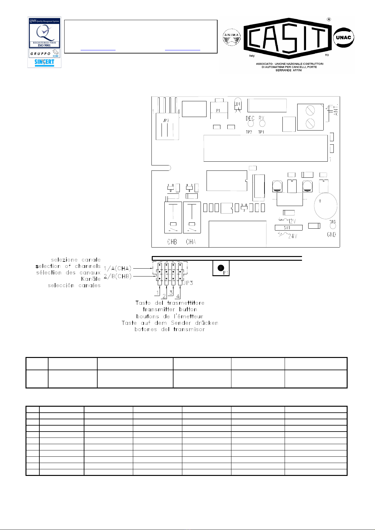
4. KANALADRESSEN UND FUNKTIONSWEISE RELAIS
Für die Anwahl der Kanäle siehe Abbildung 1.
Positionierung das jumper bestimmt sich die Vereinigung der Anschläge des trasmetteur bis das relè CHA (Kanal 1) und CHB (Kanal die 2) und relative
Taste auf dem Sender drücken
Basisposition:
•CHA Taste auf dem Sender drücken 1
•CHB Taste auf dem Sender drücken 2
5. ANTENNE
•Die Installation der Antenne ist von äußerster Wichtigkeit; nachdem sie mit dem Empfänger verbunden ist, stellt sie den Empfangspunkt für die
Funksteuerung dar. Bei ihrer Installation ist folgendes zu beachten: Der Empfänger ist mit einer eigenen Antenne ausgestattet, die aus einem Stück
Draht besteht, der 170 mm lang ist. Alternativ kann eine passende Antenne verwendet werden, die mittels einem Koaxialkabel RG 58( Impedanz 50Ω)
mit einer maximalen Länge von 15 m an den Empfänger angeschlossen wird. Die Antenne wird im Freien am höchsten und sichtbarsten Punkt von
Metallstrukturen entfernt, positioniert.
•Verwendet die antenne an den empfänger no an den elektronische zentrale.
Die Installation von zwei Empfängern, zwischen denen kein Mindestabstand von 5m eingehalten wird, ist nicht möglich. Es ist ratsam, den Empfänger in
gebührendem Abstand zu Computersystem, Alarmanlagen und anderen möglichen Störungsquellen aufzustellen.
(Eine unsachgemäße Aufstellung und verwertung von stück non CASIT könnte den Betrieb teilweise gefährden und auschlub der garantie)
KONFORMITÄTSERKLÄRUNG
Die Firma CASIT erklärt hiermit, daß das folgende Gerät EMPFÄNGER ERS20SB IN ÜBEREINSTIMMUNG STEHT MIT DEN VORGABEN DER RICHTLINIE
99/05/EWG (R &TTE)
Die Erklärung von vollständiger Übereinstimmung ist bei CASIT verfügbar
D

ERS20SB Rev. 02 del 26/05/2008
Stab.: Strada Pietra Alta 1 – C.a.p. 10040 CASELETTE (TO) Italy
Tel. 011/9688230 - 9688170 Fax 011/9688363 –
Partita IVA 0050659.001.7
Reg. Trib. Torino N.654/62 - C.C.I.A.A. 333122 - M: T0024777
Sito www.casit.it E-Mail [email protected]
Cancelli Automatici Shed Infissi Telecomandati
INSTRUCCIONES RADIO RECEPTOR ERS20SB
1. Codificación Rolling
La finalidad de esta codificación es la de impedir la posibilidad de violación del código por captura y retransmisión. La codificación rolling lleva consigo la
transmisión de una trama de bits constituida por una parte constante, distinta en cada transmisor, por los bits de canal, correspondientes a los botones del
transmisor activado, más una parte que cambia en cada transmisor de forma seudo-aleatoria (código rolling) según un algoritmo propietario CASIT. La
configuración de estos bits cambia entre dos transmisiones sucesivas de forma no previsible. El receptor memoriza por autoaprendizaje la parte del código
constante de cada transmisor además del código rolling correspondiente y pone al día este último en cada transmisión. El transmisor sólo se reconoce si
envía un código rolling correspondiente a las 255 configuraciones siguientes a la última transmisión reconocida. Permite, sin embargo, la alineación y el
reconocimiento de un transmisor memorizado anteriormente y que hubiera salido de la distancia permitida ( por ejemplo por un exceso de transmisiones no
reconocidas), pulsando y soltando el botón de aprendizaje del transmisor: se analiza que el código sea correcto, manteniendo las ventajas de la codificación
variable. Función RPA (mando de autoaprendizaje a distancia del transmisor).
Uso previsto del equipo: radio receptor en sistemas por puertas de garaje.
2. Características técnicas
Alimentación 12-24 V AC/DC
Consumo medio trabajo/descanso 25 mA / 45 mA
Frecuencia de recepción 433.920 MHz
Estabilidad de frecuencia ± 100 kHz
Sensibilidad 1.5 µV
Banda pasante > 25 kHz
Código Digital 54 bits
N. códigos que se pueden memorizar 200
N. de salidas 2
Tipo de salida monoestable
Salida relé
Capacidad contactos 0,5 A @ 24 V ac/dc
Señalizaciones led rojo
Temperatura de funcionamiento -10/+55 °C
Temperatura de almacenamiento -40/+85 °C
Dimensiones/Peso 100 x 63 x 17 500g
3. Programación y eliminación de los códigos
En el receptor se pueden llevar a cabo las operaciones de introducción en la memoria de un nuevo código y de eliminación de toda la lista de códigos.
Programación
•Alimentar correctamente el receptor.
•Para presionar el pulsador P1 por un momento : el led rojo se enciende para señalar que la programación está en marcha.
•Llevar a cabo una transmisión pulsando uno cualquiera de los botones del transmisor.
•El código se introduce en la memoria. Durante la introducción el led relampaguea. Al final el led vuelve al estado de encendido fijo para señalar que es
posible introducir un código nuevo.
•Memorizar todos los transmisores llevando a cabo una transmisión con cada uno de ellos.
•Al final de la operación pulsar de nuevo el botón P1 para salir del procedimiento. El led se apaga. La salida del procedimiento se produce de todos modos
de forma automática después de 10 seg. desde la última memorización.
•Quitando también la alimentación al receptor los códigos permanecen en la memoria.
Eliminación total de los códigos
•Pulsar y mantener pulsado el botón P1 hasta que el led rojo empieza a relampaguear.
•Pulsar de nuevo el botón P1 antes de que pasen 6 segundos, para confirmar la eliminación. La confirmación se señala a través del relampagueo del led
con una frecuencia más elevada.
4. SELECCIÓN DE LOS CANALES Y MODALIDADES DEL FUNCIONAMIENTO DEL RELÉ
Para seleccionar los canales ver la figura 1.
Colocación el jumper se determina a la unión de las teclas del trasmetteur al relè CHA (canal 1) y CHB (canal los días 2) y relativas botones del
transmisor.
Posición básica:
•CHA botones del transmisor 1
•CHB botones del transmisor 2
5. ANTENA
•La instalaciòn de la antena es fundamental; conectada al receptor representa el punto de recepciòn del radiomando. Durante su instalaciòn hay que
cumplir las instrucciones siguientes: el receptor està dotado de antena propia, que consta de un trozo de hilo rigido, de 170 mm. de largo. En alternativa
es posible utilizar una antena acordada a conectar al receptor mediante un cable coaxial RG58 (impedancia 50Ω) de 15m. de largo como màximo. La
antena se debe colocar al exterior en el sitio màs elevado y visible, lejos de estructuras metàlicas.
•Connectar l’antenna a la radioreceptor y non a la centralita.
No es posible efectuar la instalaciòn de dos receptores que no tengan la distancia minima de 5 m. entre sì. Es buena regla colocar el receptor a cierta
distancia de las redes de sistemas computarizados, instalaciones de alarma y otras fuentes de pertubaciones posibles.
(Su colocaciòn incorrecta y utilizacion de piezas non CASIT puede perjudicar el funcionamiento y l’exclusion de la garantia)
DECLARACIÓN DE CONFORMIDAD
La CASIT declara que el RECEPTOR ERS20SB ESTA EN CONFORMIDAD con los requisitos fundamentales de la norma 99/05/EC (R&TTE)
La declaración de conformidad completa está disponible cerca de CASIT
E

ERS20SB Rev. 02 del 26/05/2008
Stab.: Strada Pietra Alta 1 – C.a.p. 10040 CASELETTE (TO) Italy
Tel. 011/9688230 - 9688170 Fax 011/9688363 –
Partita IVA 0050659.001.7
Reg. Trib. Torino N.654/62 - C.C.I.A.A. 333122 - M: T0024777
Sito www.casit.it E-Mail [email protected]
Cancelli Automatici Shed Infissi Telecomandati
JP3
Jumper (Jp3) di
selezione canali Jumper (Jp4) for selection of
channels Cavalier (Jp4) de
sélection des canaux Jumper (Jp4) Anwahl
Kanäle Puente (JP4) de
selección canales.
P1
Pulsante di
programmazione e
cancellazione
Programming and cancellation
button
Bouton de
programmation et
d’effacement
Programm- und
Löschtaste Botón de programación y
cancelación
N° MORSETTIERA TERMINAL LIST BOÎTE À BORNES KLEMMENBRETT KLEMMENBRETT TABLERO DE BORNES
1 COM canale B COM channel B COM canal B COM canal B COM Kanal B COM canal B
2 N.O. canale B N.O. channel B N.O. canal B N.O. canal B N.O. Kanal B N.O. canal B
3 N.C. canale B N.C. channel B N.F. canal B N.F. canal B N.G. Kanal B N.C. canal B
4 non connesso not connected non relié non relié Nicht angeschlossen no conectado
5 N.O. canale A N.O. channel A N.O. canal A N.O. canal A N.O. Kanal A N.O. canal A
6 COM canale A COM channel A COM canal A COM canal A COM Kanal A COM canal A
7 12 - 24 V AC/DC 12 - 24 V AC/DC 12 - 24 V AC/DC 12 - 24 V AC/DC 12 - 24 V AC/DC 12 - 24 V AC/DC
8 GND GND GND GND GND GND
9 non connesso not connected non relié non relié Nicht angeschlossen no conectado
10 non connesso not connected non relié non relié Nicht angeschlossen no conectado
FIG.1
Table of contents
Languages:
Other Casit Receiver manuals