3c. Large Talon Stake Mounting Instructions.
• To assemble stake, insert flat end of each spike into stake body receptacles.
Secure set screws with 3/32” hex bit.
• Prepare turf or bed area by removing plant material or mulch to attain a firm soil
surface of about 6” diameter. Tamp down soil and test with bubble level to ensure
surface is level. If desired (for aesthetic reasons), Talon Stake body can be set 1”
below grade then covered with soil or mulch.
• Position stake so wire opening faces wire trench.
• Drive stake into ground prior to attaching fixture. Use rubber or dead blow mallet
to drive talon into ground. Strike directly above each spike in turn, driving stake
into ground in steady increments to ensure pins enter vertically. Continue striking
until body is firmly seated in soil.
• Extend narrow trench to directly beneath center of stake. Insert fixture lead wire
through wire opening. Insert fixture stem into stake receptacle. Secure thumb
screw. Back-fill wire trench and, if needed, cover stake with soil or mulch.
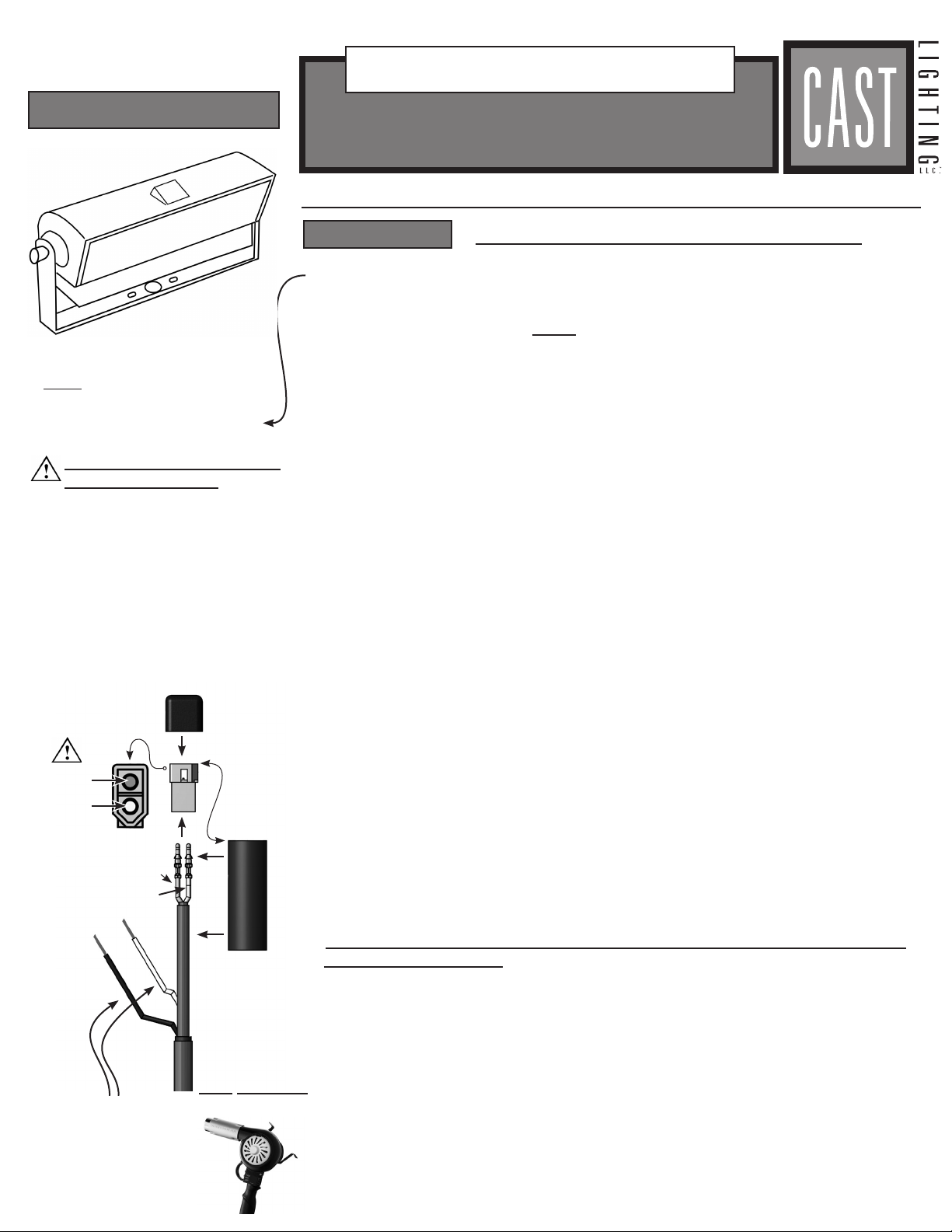
1. LIGHT LEVEL ADJUSTMENT INSTRUCTIONS.
All CAST Impressionist Series fixtures have built-in light level control. This can be
activated in two ways - using the provided Manual Dimmer Control Jumper Cable
or with the CAST Impressionist Dimmer Control (CDIMMER). Both of these devices
plug into the Fixture Control Plug located on the fixture lead wire.
• Manual Dimmer Control Jumper Cable (CIJ). Plugging this device into the fix-
ture wire Control Plug will activate the dimming (up or down) sequence. Each time
the device is plugged in (while fixture is powered) the dimming cycle reverses. As
long as the device is plugged in, the fixture will dim up or down until the maxi-
mum (100%) or minimum (5%) is reached. If the plug is left in place for 15 sec.
after either of these limits are reached, then the fixture resets to 100%. When the
device is unplugged, the fixture retains the specific light level even when not pow-
ered.
• CAST Impressionist Dimmer Control (CDIMMER). Connect CDIMMER plug to
fixture wire Control Plug. Switch unit “ON”. Depress and hold “DIM” button to dim
light up or down. Each time button is depressed, dimming direction reverses. To
bring fixture to 100%, depress and hold button for 15 sec. Store unit in cool dry
place. Change batteries yearly.
LUMINAIRE ADJUSTMENTS
SAFETY INSTRUCTIONS
• WARNING - Risk of Electric Shock. Install
all luminaires less than 10 ft. (3.05 m) or
more from a pool, spa, or fountain.
• Follow NEC guidelines for outdoor low volt-
age wiring.
• Obey all local electrical codes and require-
ments.
• Use only 25A/circuit 12-volt power supply.
• A luminaire shall not use tungsten halogen
lamps unless the luminaire is marked for
such lamps.
• The luminaire’s low voltage cable shall:
a. be protected by routing in close proxim-
ity to the luminaire or fitting, or next to
a building structure such as a house or
deck;
b. not be buried except for a maximum 6
inches (15.2 cm) in order to connect to
the main low voltage cable.; and,
Electrical Requirements
Input Voltage:
10-24V AC/DC
Power Supply*:
Must use a toroidal magnetic
transformer to supply low
voltage power (such as CAST
Journeyman, Master, and
Perimeter Series).
Wire:
For maximum system lon-
gevity, use tin-coated
marine-grade wire (such as
CAST No-Ox® Wire).
Connectors:
For connecting single or
multiple wires, use robust
waterproof connectors and
junctions (such as CAST
Spider Splice Junction
Box and CAST Butt Crimp
Connectors).
*Use of approved power sup-
ply activates extended war-
ranty.
Electrical Consumption:
Wattage: 8.3 W
Power Factor: 8.7
Volt-Amps: 9.5 VA
(for wire and transformer
sizing; and voltage loss cal-
culations)
c. have the length cut off so that it is con-
nected to a connector within 6 inches
(15.2 cm (from a building structure, a
luminaire, or fitting.
• Contact only switch or plug when turning
system on or off at transformer.
• Do not look directly into a lighted lamp.
• Do not operate the lighting fixture if dam-
aged.
• Do not mount stake mounted fixtures in
tree application. Use Tree-Mount fixture
only!!
• Unplug transformer while installing and
connecting luminaires.
• Main low voltage cable is intended for shal-
low burial - less than 6” (152 mm) - unless
the manufacturer has provided wiring suit-
able for direct burial.
© 2013 CAST Lighting, 1120-A Goffle Rd., Hawthorne NJ 07506. Patents Pending. 4-10-13 ORDER# CLITIMPW