CAT Pumps DUPM623 User manual

Wash Prep Systems featuring CAT PUMPS®
DUPM623
DUPM820 / DUPM820-TS
DUPM820D / DUPM820D-TS
DUPM1010
Owner’s Manual #0779 072415
Serial Number: Installation Date:

Please read and
understand this
manual. Store in
safe location for
future reference.
IMPORTANT
Everyone who operates this unit should understand basic operations and safety precautions!
The time you take to fully understand the proper installation, maintenance and use of the machine will
prolong its service life, and assure you of trouble free operation.
When unpacking, check to make sure all the parts shown on the Parts Breakdown near the end of this
manual are included. If any parts are missing or broken, please call Dultmeier Sales as soon as possible.
Consumers should notice that this manual may differ slightly from the actual product as more improvements
are made to our products. Some of the pictures in this manual may differ slightly from the actual product
as well. Dultmeier Sales reserves the right to update designs and / or change the specifications at any
time without incurring any obligation to install them on units previously sold.
If you have any questions or suggestions about this manual, please contact us.
Dultmeier Sales, LLC
1.800.228.9666 • Fax: 1.402.333.5546 • 13808 Industrial Road Omaha, NE 68137
1.800.553.6975 • Fax: 1.319.386.5448 • 601 West 76th Street Davenport, IA 52806
http://www.dultmeier.com • [email protected]
Table of Contents
Safety Information ................................................................................................................................... 1
Specifications .......................................................................................................................................... 2-3
Installation................................................................................................................................................ 4
Operation ................................................................................................................................................. 5
Maintenance & Storage ............................................................................................................................. 6
Parts Breakdown ...................................................................................................................................... 7-9
Warranty Information ............................................................................................................................... 10
Checklist .................................................................................................................................................. 11

This is a Safety Alert Symbol -
When you see this symbol in the manual, look for the following signal words &
be alert to the potential for personal injury or property damage.
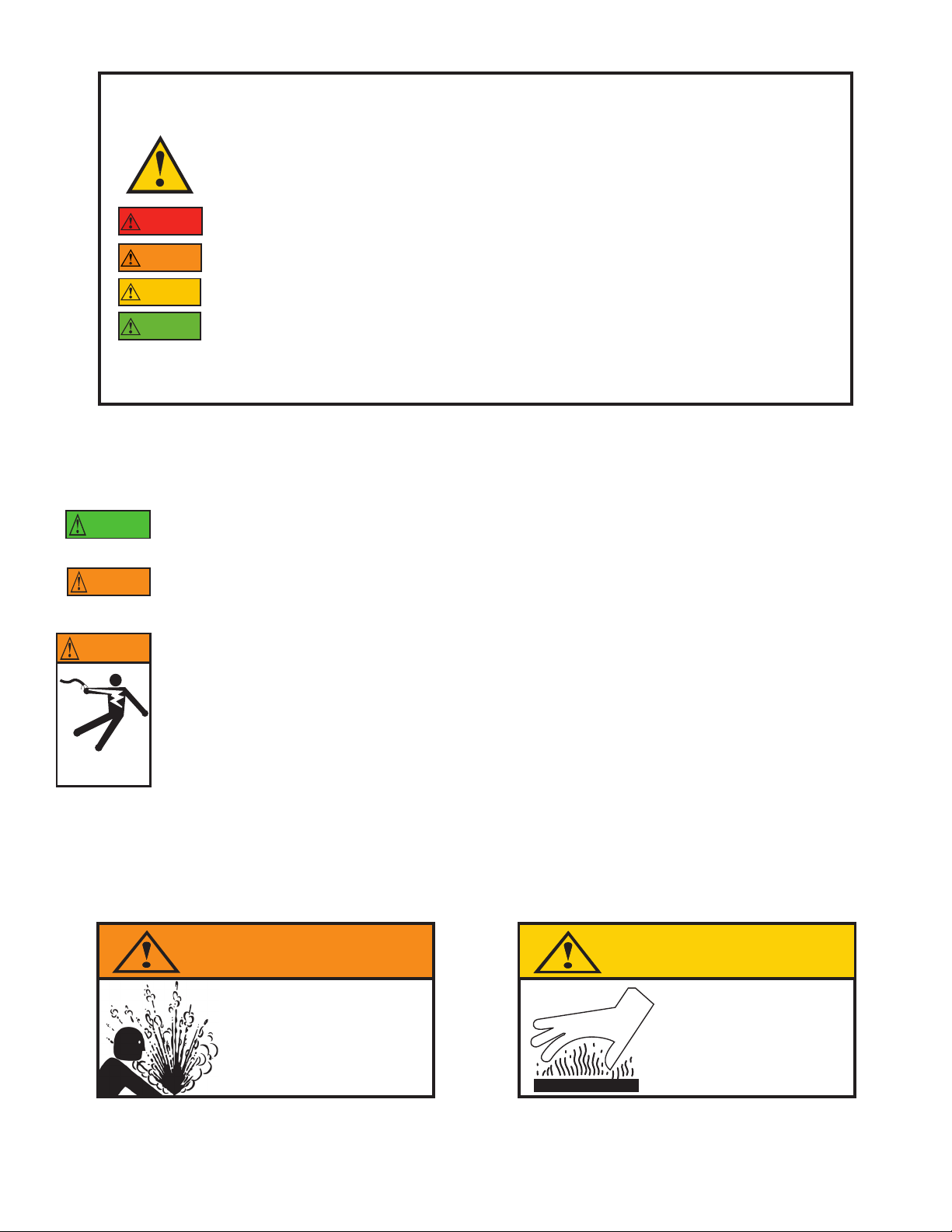
Warns of potential hazards that WILL cause serious personal injury, death or property damage.
Warns of potential hazards that CAN cause serious personal injury, death or property damage.
Warns of potential hazards that WILL or CAN cause minor personal injury, death or property damage.
Indicates special instructions that MUST be followed but not related to hazards.
To avoid serious or fatal personal injury or major property damage,
read and follow all safety and operation instructions in the manual.
This manual is intended to assist in the installation and operation of this unit.
Do not attempt to operate this unit without reading and understanding this manual.
DANGER
WARNING
IMPORTANT
CAUTION
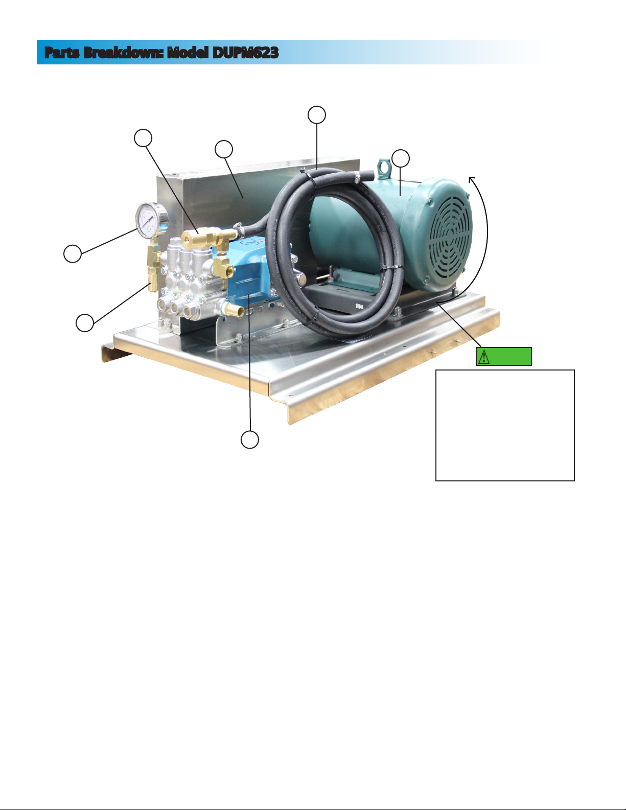
Safety Information | 1
General Safety
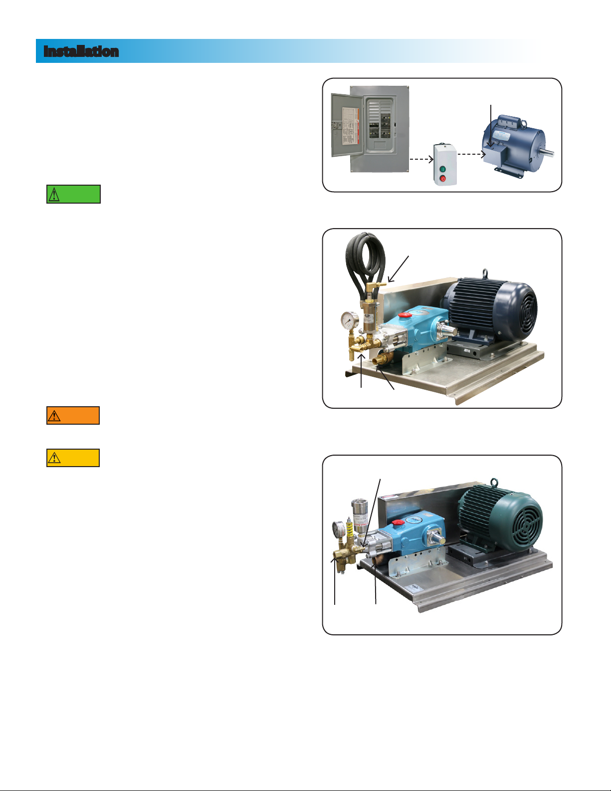
To avoid the risk of serious bodily injury and property damage, read safety instructions carefully before installing
this system. Follow all local and/or national plumbing and electrical codes when installing.
Do Not Allow System or Components to Freeze.
To do so may damage the system and will void the warranty.
Never Run the System Dry.
Running the unit dry (without fluid) can damage internal parts, overheat pump (which can cause
burns to people handling or servicing the pump), and will void the warranty.
Risk of Electric Shock.
Keep the unit dry at all times -
Do not wash the motor or electrical panel or allow the unit to sit in standing water.
Use only Ground Fault Circuit Interrupter (GFCI) protected grounded outlet for the cord plug.
If you must use an extension cord, use only UL approved indoor/outdoor, 3-wire, grounding
type cords. The cord must be rated to support amp draw. Do not allow any part of cord or
receptacle ends to sit in water.
To avoid fatal shocks, proceed as follows if service is needed:
A. Turn off water to the system.
B. Disconnect the power at main electrical service before unplugging the unit.
C. Ground the electrical outlet box.
D. Take extreme care when changing fuses.
WARNING
Hazardous voltage
can shock, burn
or cause death.
IMPORTANT
WARNING
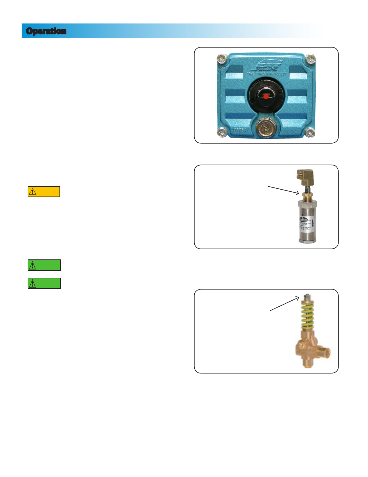
Modern motors can operate at high temperatures.
To avoid burns when servicing pump, allow it
to cool for 20 minutes after shutdown before
handling.
Do not run the unit with discharge shut off, as
hose may burst or damage may occur.
WARNING
Burst Hazard
High Pressure Unit
CAUTIONCAUTION
Burn Hazard
Do Not Touch An
Operating Motor

DUPM623 Wash Prep System Specifications
Specifications | 2
System Features
Model ...................................................... DUPM623
Style ........................................................ High Pressure Piston Pump
Capacity .................................................. 6 GPM
PSI ........................................................... 1200
Maximum Inlet Pressure........................... 40 PSI
Maximum Inlet Temperature .................... 130° F
*See Included CAT PUMPS® Service Manual for Higher Temperatures
Motor ......................................................
Pump....................................................... CC623
Crankcase Capacity.................................. 40 oz.
Pump Drive.............................................. Belt
Pump Inlet ............................................... 1”
Pump Discharge....................................... 3/4” (3 qty.)
Dimensions.............................................. Approx. 34”L x 22”W x 16”H
Shipping Weight....................................... Approx. lbs.
CAT PUMPS® Piston Pump belt driven by Leeson Motor
Heavy Duty Stainless Steel Baseplate & Belt Guard
Adjustable Motor Baseplate
Adjustable Balanced Relief Valve
Safety Pop Off Valve
2300# Gylcerin Filled Pressure Gauge
Units are Pre-Plumbed and Tested Prior to Shipment
CE131464 5 HP, 3 PH
Volts: 208 - 230 460
Amps: 13.7 - 12.6 6.3

Motor ...................................................... CEEM3710T
Maximum Inlet Pressure........................... 40 PSI
Maximum Inlet Temperature .................... 130° F *See Included CAT PUMPS® Service Manual for Higher Temperatures
Crankcase Capacity.................................. 40 oz.
Pump Drive.............................................. Belt
Pump Inlet ............................................... 1”
Pump Discharge....................................... 3/4” (3 qty.)
Features................................................... Adjustable Pressure Unloader Valve, Chemical Injector, Pressure
................................................................ Gauge, Safety Pop Off Valve, 50’ High Pressure Hose, Trigger
................................................................ Style Spray Gun with: Insulated Extension, Gun Swivel, and Spray
................................................................ Nozzle; and Heavy Duty Stainless Steel Base Plate. All units are
................................................................ Pre-Assembled and tested prior to shipping.
PM820 Wash Prep System Specifications
Specifications | 3
Common Specifications
CEEM3710T 7.5 HP, 3 PH
Volts: 230 460
Amps: 18.8 9.4
DUPM820
PSI .................................. 1000.............................Style .....................................Prep Wash Unit
Capacity ......................... 10 GPM .........................Dimension ................. Approx. 39”L x 24”W x 21”H
Pump.............................. CC 820 .........................Weight ................................ Approx. 313 lbs.
DUPM820-TS
PSI .................................. 1000.............................Style .............SIngle Gun Prep Wash Unit on Stand with Tank
Capacity ......................... 10 GPM .........................Dimension ................. Approx. 45”L x 27”W x 70”H
Pump.............................. CC 820 .........................Weight ................................ Approx. 400 lbs.
DUPM820D
PSI .................................. 1000.............................Style ........................... Double Gun Prep Wash Unit
Capacity ......................... 10 GPM .........................Dimension ................. Approx. 39”L x 24”W x 21”H
Pump.............................. CC 820 .........................Weight ................................ Approx. 313 lbs.
DUPM820D-TS
PSI .................................. 1000.............................Style ............Double Gun Prep Wash Unit on Stand with Tank
Capacity ......................... 10 GPM .........................Dimension ................. Approx. 45”L x 27”W x 70”H
Pump.............................. CC 820 .........................Weight ................................ Approx. 400 lbs.
DUPM1010
PSI .................................. 700...............................Style .....................................Prep Wash Unit
Capacity ......................... 13 GPM .........................Dimension ................. Approx. 41”L x 18”W x 19”H
Pump.............................. CC 1010 .......................Weight ................................ Approx. 320 lbs.

1. Select a location for your new unit. Place near
floor drain, and electrical and water sources. Floor
surface must be level.
2. Electrician to run power from main supply panel
to motor starter or stop start station, and then to
motor wiring box. Check motor wiring schematic
to ensure wired for proper voltage. (Fig. 1)
Follow all local codes for proper
fittings, conduit, and wire sizing.
3. Loosely fit clamps on low pressure hoses.
4. Install low pressure hose from supply (tank) to
inlet of pump. (Fig. 2)
If you purchased a complete unit (PM820-TS or
PM820D-TS) run low pressure hose from supply to
inlet of tank.
5. Attach bypass line from regulator to tank.
(see fig. 2) (See fig. 2A for PM1010)
6. Run high pressure line(s) from pump outlet to
wash bay(s).
Hazardous Pressure.
Do not discharge toward
animals or humans.
Hazardous Pressure.
Do not exceed pressure
rating of pump.
7. Tighten all clamps and fittings.
Installation & Operating Instructions | 4
Installation
WARNING
CAUTION
IMPORTANT
figure 1
Start Stop
Station
Motor Wiring Box
Main Supply Panel
Bypass to Tank
Bypass to Tank
Outlet
Outlet
Inlet
Inlet
figure 2
figure 2A

Installation & Operating Instructions | 5
Operation
1. Check pump for proper oil level. The pump should
be filled to or slightly above the red dot on the
bubble gauge, located on the back of the pump.
(Fig. 3)
2. Turn on water to the system and allow air to
purge.
3. While holding the trigger gun open, start system.
(All units are tested at production and
pressure should come up to specifications.)
When the trigger gun is closed, the balanced relief
valve will bypass flow back to inlet of pump, or
to tank. Pressure may fluctuate by 100 PSI when
in bypass mode. Ensure that pressure is balanced
with one or two guns.
Leaving the pump in bypass mode
for more than a few minutes can
damage pump due to friction heat
buildup.
4. Pressure can be adjusted by turning the nut on
the balanced relief valve. (Fig. 4, 4A)
Clockwise............................ More Pressure
Counter-Clockwise.......... Less Pressure
Pump oil must be changed per
manufacturer’s recommendations.
Do not run pump with frozen liquid.
CAUTION
IMPORTANT
IMPORTANT
figure 3
Balanced Relief Valve
Adjusting Nut
Unloader Valve
Pressure Adjusting Nut
figure 4
figure 4A
For PM623, PM820*** Units
For PM1010 Only

Maintenance & Storage
Maintenance & Storage | 6
1. Change the oil after intial 50 hours. Use CAT
PUMPS® Oil, part number CC6100-1 for 21 oz.
bottles or CC6105-1 for 2.5 gallon jug. (Fig. 5)
This pump takes 40 oz.
2. The oil should be changed every 500 hours. If
other than CAT PUMPS® special custom blend
multi-viscosity ISO68 hydraulic oil is used, change
the oil every 300 hours.
3. Regulating Unloader Valve should be serviced or
replaced when leaks occur or if not functioning
properly.
4. For extended storage or between use in cold
climates, drain all pumped liquids from pump
and flush with antifreeze to prevent freezing and
damage to the pump. When running antifreeze
through system, open and close trigger gun so
entire system is protected.
IMPORTANT
figure 5
Please refer to the included CAT PUMPS® reference materials for additional
information on the Maintenance & Storage of your CAT PUMPS® Pressure Washer.

Parts Breakdown | 7
Parts Breakdown: Model DUPM623
Item Part Number Description
1.......... CC5CP6120............. Cat Plunger Pump
2.......... GU22568................. Safety Pop Off Valve, 1/4” Blue
3.......... AH2750-3 ............... 2300# Liquid Filled Pressure Gauge
4.......... NPST230 ................. Balanced Relief Valve
5.......... GABX47................... V-Belt, 47” (2 qty. - Not Visible)
6.......... GA3204-1425.......... 10’ of 3/4” bypass hose
7.......... CE131464 ............... Leeson Motor, 5 HP, 3 PH
5
1
2
4
7
3
Pump Rotation:
Pump was designed for
forward rotation to allow
optimum lubrication of the
crosshead area. Reverse
rotation is acceptable if
the crankcase oil level is
increased slightly above
center dot to assure
adequate lubrication.
IMPORTANT
6

Parts Breakdown | 8
Parts Breakdown: Model DUPM820, DUPM820D
Item Part Number Description
1.......... CC820..................... Cat Piston Pump
2.......... GU22531A .............. Safety Pop Off Valve
3.......... AH2750-3 ............... 2300# Liquid Filled Pressure Gauge
4.......... UPBR10-1.5 ............. Balanced Relief Valve
5.......... GABX47................... V-Belt, 47” (2 qty. - Not Visible)
6.......... CEEM3710T............. Baldor Motor, 7.5 HP, 3 PH
Also may be included but not shown:
.......... GA6HR25*............... 25’ Black Wash Hose
.......... NPST004-D42* ........ Nozzle Protector
.......... NPST007-24*........... 23” Wand Extension w/ Grip
.......... NPST1500*.............. Spray Wand
.......... NPST300*................ Swivel, 3/8” Brass
.......... SS1/8MEG2510* ...... Washjet Nozzle
.......... HR561* ................... Hydrominder
*Double quantity on DUPM820D
5
1
2
4
6
3
Pump Rotation:
Pump was designed for
forward rotation to allow
optimum lubrication of the
crosshead area. Reverse
rotation is acceptable if
the crankcase oil level is
increased slightly above
center dot to assure
adequate lubrication.
IMPORTANT

Parts Breakdown | 9
Parts Breakdown: Model DUPM820-TS, DUPM820D-TS
5
1
2
4
3
Item Part Number Description
1.......... CC820..................... Cat Piston Pump
2.......... GU22531A .............. Safety Pop Off Valve
3.......... AH2750-3 ............... 2300# Liquid Filled Pressure Gauge
4.......... GABX47................... V-Belt, 47” (2 qty. - Not Visible)
5.......... UPBR10-1.5 ............. Balanced Relief Valve
6.......... CEEM3710T............. Baldor Motor, 7.5 HP, 3 PH
Also may be included but not shown:
.......... GA6HR25*............... 25’ Black Wash Hose
.......... NPST004-D42* ........ Nozzle Protector
.......... NPST007-24*........... 23” Wand Extension w/ Grip
.......... NPST1500*.............. Spray Wand
.......... NPST300*................ Swivel, 3/8” Brass
.......... SS1/8MEG2510* ...... Washjet Nozzle
.......... HR561* ................... Hydrominder
*Double quantity on DUPM820D-TS

Notice Regarding Manufacturer’s Limited Warranty
Dultmeier Sales Limited Liability Company (hereinafter Dultmeier), notifies you that component
part(s) carry a manufacturer’s limited warranty provided by the manufacturer of said component
part(s). These warranties do not pertain to normal wear of component part(s) that may occur
within any specified period. While Dultmeier is not the manufacturer of any of the component
part(s), Dultmeier will assist you in processing any and all manufacturer’s warranty claim if
applicable and available. Any and all manufacturer’s claims must be submitted in writing to the
manufacturer within the warranty periods provided by the manufacturer.
Defective component part(s) that are to be considered for manufacturer’s limited warranty must
be returned to the manufacturer by prepaid shipment with the applicable manufacturer’s limited
warranty period. If the component part(s) are deemed to be defective under the manufacturer’s
warranty, Dultmeier will assist in obtaining a replacement or repair of the component part(s). Said
component part(s) will be returned F.O.B. Omaha, Nebraska. Replacement or repair shall be the
exclusive remedy for any breach of warranty. Labor for installation, either with respect to original
or replacement part or components, is not covered under the manufacturer’s limited warranty.
Neither the manufacturer nor Dultmeier warrants loss of income or consequential damages for
injury or commercial loss resulting from any breach of warranty or warranties stated above.
The manufacturer’s limited warranty as stated does not apply to component part(s) which
have been improperly installed, misused, altered, neglected, abused or not installed, adjusted,
maintained, or used in accordance with applicable codes and ordinances and in accordance with
the manufacturer’s specifications as to such factors.
Notwithstanding Dultmeier’s willingness to assist in the processing of the manufacturer’s limited
warranty, Dultmeier makes no warranty against infringement of the like, makes no warranty
of merchantability, makes no warranty of fitness for a particular purpose, and makes no other
warranty, express or implied, including implied warranty arising from the course of dealing or
usage of trade.
Compliance with all local, state and federal codes regarding the installation and operation of said
equipment, parts and components shall be the responsibility of the purchaser. The rights and
obligations of the parties shall be governed by the laws of the State of Nebraska.
Dultmeier Sales • 1-800-228-9666 Omaha, NE • 1-800-553-6975 Davenport, IA
Warranty Information | 10

Checklist | 11
If you have any questions or concerns about condition of this unit, please contact us before operating.
Dultmeier Sales, LLC
Omaha, NE 1.800.228.9666 •Davenport, IA 1.800.553.6975
Production Checklist
Checked By
Tested
OK NA
Oil Level
Clamps Tight
Bolts Tight & Anti-Seized
Belts Tight
Pulleys Aligned & Torqued to Specifications
Fittings Straight
Winterized
OK NA
OK NA
OK NA
OK NA
OK NA
OK NA
OK NA
OK NA
OK NA
OK NA
OK NA
OK NA
Pop-Off Valve Set PSI
Unloader Valve Locked
PSI
Pump RPM
Motor Amps
Motor Wired For
OK NA
OK NA
OK NA
OK NA
OK NA
OK NA
Accessories
Safety Pop Off Valve
Trigger Gun 1 2
High Pressure Hose
Injector / Injector Hose
Gauge
OK NA
OK NA
OK NA
OK NA
OK NA
OK NA
Built By
Customer Checklist
OK NA
OK NA
OK NA
OK NA
Shipping Container Was In Good Shape
Accessories Included
Oil Level To Manufacturer’s Specifications
Overall Condition
This manual suits for next models
5
Table of contents