CBC ZC-NAF27 User manual

Operating Instructions
ZC-NAF27
Before installing and using the camera,
please read these instructions throughly
and retain them for later reference.
S

2
Warning
This is a class A product. In a domestic environment this product
may cause radio interference in which case the user may be
required to take adequate measures.
This symbol is intended to alert
the user to the presence of
uninsulated “dangerous voltage”
within the product’s enclosure
that may be of sufficient
magnitude to constitute a risk
of electric shock to persons.
This symbol is intended to
alert the user to the presence
of important operating and
maintenance (servicing)
instructions in the literature
accompanying the appliance.
CAUTION TO REDUCETHE RISK OF ELECTRIC SHOCK,
DO NOT REMOVE COVER (OR BACK).
NO USER SERVICEABLE PARTS INSIDE,
REFER SERVICING TO QUALIFIED SERVICE PERSONNEL.
CAUTION
RISK OF ELECTRIC SHOCK
DO NOT OPEN
Warning
Regulatory Notices For U.S.A
To prevent fire or shock hazard, do not expose the unit to rain or moisture.
To avoid electrical shock, do not open the cabinet Refer servicing
to qualified personnel only.
This equipment has been tested and found to comply with the limits for a Class A
digital device, pursuant to Part 15 of the FCC Rules.These limits are designed to
provide reasonable protection against harmful interference when the equipment is
opearted in a commercial environment.This equipment generates, uses, and can
radiate radio frequency energy and, if not installed and used in accordance with
the instruction manual, may cause harmful interference to radio communications.
Operation of this equipment in a residential area is likely to cause harmful
interference in which case the user will be required to correct the interference at his
own expense.
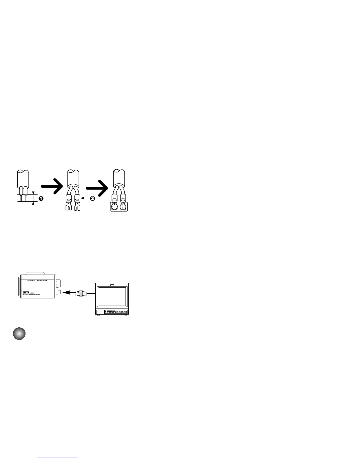
• A suitable conduit entries, knock-outs or glands shall be provided in thecable
entries of this product in the end user.
• Caution:Danger of explosion if battery is incorrectly replaced. Replacedonly
with the same or equivalent type recommended by the manufacturer. Dispose of
used batteries according to the manufacturer's instructions.
• Holes in metal, through which insulated wires pass, shall have smoothwell
rounded surfaces or shall be provided with brushings.

3
Contents
Features................................................................................................................................................................................ 3
Cautions for Safe Operation .............................................................................................................................................. 4
Operating Controls andTheir Functions........................................................................................................................... 5
Connections ........................................................................................................................................................................ 6
Control ................................................................................................................................................................................. 7
MENU DESCRIPTIONS ....................................................................................................................................................... 8
CAMERA ID ........................................................................................................................................................... 9
FOCUS MODE SET .......................................................................................................................................... 10-11
AWB SET ......................................................................................................................................................... 12-13
AE SET ............................................................................................................................................................ 14-16
SPECIAL SET .................................................................................................................................................. 17-18
MOTION DET ....................................................................................................................................................... 19
F. OSD SET .......................................................................................................................................................... 20
E. SENSITIVITY ................................................................................................................................................... 21
WDR SET .............................................................................................................................................................. 22
On-Screen Display........................................................................................................................................................ 23-24
Specifications ............................................................................................................................................................... 25-26
RS-422/RS-485 Command........................................................................................................................................... 27-66
FEATURES
• The power zoom color video camera is designed for use in monitoring system.
• High resolution and high sensitivity with a 1/4 inch CCD (Charge Coupled Device)
• High magnitude of zoom lens with optical X 27, Digital X 270(MAX)
• Auto Focus
• Auto White balance
• Auto exposure with DC Iris control
• Day & Night function
• DSS(Digital Slow Shutter) is available.
• WDR(Wide Dynamic Range) is available.

4
Cautions for Safe Operation
PowerSupply • Close to generators of powerful
Thiscameramustalwaysbeoperateda12VDC electromagnetic radiation such as radio or TV
powersupply.(Morethan500mA) transmitters.
Careoftheunit
Handlingoftheunit • Remove dust or dirt on the surface of the lens
Be careful not to spill water or other liquids on withablower.
the unit, or to get combustible or metallic • Useadrysoftclothtocleanthebody.Ifitisvery
material inside the body. If used with foreign dirty, use a cloth dampened with a small
matterinside, the camera isliableto fail, or to be quantityofneutraldetergent,thenwipedry.
acauseoffireorelectricshock. • Avoid the use of volatile solvents such as
thinners, alcohol, benzene, and insecticides.
Operatingandstoragelocation They may damage the surface finish and/or
Avoid viewing a very bright object (such as light impairtheoperationofthecamera.
fittings) for an extended period.Avoid operating
orstoringtheunitinthefollowinglocations.
• Extremelyhotorcoldplaces
(operatingtemperature0°C-45°C)
• Dampordustplace
• Whereitisexposedtorain
• Whereitissubjecttostrongvibration

5
Operating Controls and Their Functions
1. Tripodadaptor
Thisadaptorcanalsobeattachedonthebottomofthecamera.
2. Lensmountcap
3. TELEKey
WhenpushtheTELEKEY,pictureistelephoto
4. WIDEKey
WhenpushtheWIDEKEY,pictureiswideangle
5. MenuKey
Ifyouwanttosetupadiversefunction,youcanpushthisbutton.
6. ControlJACK(RJ45)
ConnectRS-422interface
7. FocusFarKey
Inamanualsituation,focusgetfar.
8. FocusNearKey
Inamanualsituation,focusgetnear.
9. DC12Vscrewterminal
ConnecttoanexternalpowersupplyofDC12V.
10. HotKey
UsetogetdigitalShutterspeedmode.
11. Videooutput(BNCtype)
Connecttothevideoinconnectorofamonitor.

6
9?D
9?
Connections PowerConnection
1. Removetheinsulationonthepowercableasillustrated.
2. Attachtheterminaltips.
3. ConnecttotheDC12Vterminalsonthecamera.
Connectionthemonitor
1. ToVIDEOOUT
2. ToVideoinputonthemonitor

7
Control
CONTROL
PIN 8 PIN 1
Remote Control Lines are connected to RJ-45 socket as shown below
In case of RS-422 INTERFACE (Basic)
In case of Zoom/Focus control Interface (option)
Receiver/Controller
Voltage Range
1
2
7
8
R+
R-
T-
T+
T+
T-
R-
R+
CONTROL OUT Controller
4
5
6
ZOOM
COMMON
FOCUS
ZOOM (+Tele, -Wide)
COM
FOCUS (+Near, -Far)
+
-
Vcom + (+5~15V)
Vcom - (+5~15V)

8
page 9page 9
page 10-11page 10-11
page 12-13page 12-13
page 14-16page 14-16
page 17-18page 17-18
page 19page 19
page 20page 20
page 21page 21
page 22page 22
Using TELE, WIDE, FOCUS+, FOCUS- button
• TELE and WIDE are used for UP and DOWN.
• FOCUS+ and FOCUS-are used for INCREASE and DECREASE the data.
MENU DESCRIPTIONS

9
CAMERA ID 1.CAMERAID
To connect a large number of camera , It can be
assigned to identification number to each camera for
camera control easily. (OFF, 0 - 255 : total numbers of
IDare256)
• It only can be set this function using ID commend.
To transfer ID Code of camera , In first byte at PC
control. Set the ID number of camera , and then the
IDnumberdisplaycontinuously.

PUSH
10
2. Focus Set:
2-1. Focus Mode Set:
This function is for focus mode setting
A) Set up “FOCUS SET” in main menu using Menu key.
Select the “FOCUS MODE” in submenu using
Tele/Wide key. And then set the mode (Auto, Push
auto, or Manual) using Focus key.
2-2. Focus Distance Set:
This function is for selection of minimum shooting
distance.
A) Select the “FOCUS DIST” in submenu using
Tele/wide key.
B) Set the focus distance mode from
1cm to 5M. (1cm, 10cm, 50cm, 1M, 3M, 5M) using
Focus key.
2-3. ZOOM START Set :
This function is for selection of zoom start position.
A) Select the “ZOOM START” in submenu using
Tele/wide key.
B) Set the Zoom start mode from x1
to x27. using Focus key.

11
PUSH
FOCUS MODE SET
2-4. ZOOM END Set:
This function is for selection of zoom end position.
A) Select the “ZOOM END” in submenu using Tele/wide key.
B) Set the Zoom end mode from (Zoom Start + 1) x 270 to X using
Focus key.
2-5. ZOOM SPEED Set:
This function is for selection of zoom speed.
A) Select the “ZOOM SPEED” in submenu using Tele/wide key.
B) Set the Zoom speed, Slow, Middle , Quick using Focus key.
2-6. ZOOMTRACKING MODE Set:
This function is for selection of zoom tracking mode.
A) Select the “ZTRK” in submenu using Tele/wide Command, B) Set
the Zoom tracking mode to Auto or Manual.
* Zoom tracking means focused zooming state.
2-7. INITIAL SET:
If initial mode set to ON, All FOCUS SET function is
changed to the factory setting.
A) Select the “INITIAL SET” in submenu using Tele/wide key. B) Set
the initial set mode to ON or OFF using Focus key.
2-8. RETURNTO MAIN MENU:
This function is exit to main menu.
A) Select the “RETURN” in submenu using Tele/wide key. B) Set the
return mode using Focus key.

12
3. AWB SET
3-1.WB Mode Set:
This function is for changing theWB mode.
A) Set up “AWB SET” in main menu using Tele/wide key.
B) Select the “WB MODE” in submenu using Tele/wide key.
C) Set the mode Auto, Push auto , Manual, Outdoor, Indoor,
Special using Focus key.
*WBC MODE ; Use for changingWhite Balance Mode .
1) AUTO ;WB Range 2800 °K ~ 8000 °K.
2) PUSH AUTO ; Set the AWB mode to Push Auto, then WB Mode is
auto.
3) SPECIAL ; Under the special WB condition( Differ from curve of the
control color temperature ), Adjust Red and Blue to perform a
desired Auto White Balance.
3-2. RED ADJUST Set:
This function is available for Special ,Push Auto, ManualWB mode.
This mode is the adjustment of user option for special color.
A) Select the “RED ADJUST” in submenu using Tele/wide key.
B) Adjust the level from (-30 to 30 SPECIAL, -128 to +127 PUSH AUTO,
0-255 MANUAL) using Focus key.
AWB SET

13
3-3. BLUE ADJUST Set :
This function is available for Special ,Push Auto, ManualWB mode.
This mode is the adjustment of user option for special color.
A) Select the “BLUE ADJUST” in submenu using Tele/wide key.
B) Adjust the level from (-30 to 30 SPECIAL, -128 to +127 PUSH AUTO,
0-255 MANUAL) using Focus key.
3-4. PUSH AUTO :
In case of PUSH AUTOWB mode.
Adjust the push auto mode ON,WB act automatically.
3-5. INITIAL SET :
If initial mode set to ON, All AWB function is changed
to the factory setting
A) Select the “INITIAL SET” in submenu using Tele/wide key.
B) Set the initial set mode to ON or OFF using Focus key.
3-6. RETURNTO MAIN MENU :
This function is exit to main menu.
A) Select the “RETURN “ in submenu. Using Tele/wide key.
B) Set the return mode using Focus key.
AWB SET

14
4. AE SET
4-1. AE Mode Set:
This function is for changing to AE mode.
A) Set up “AE SET” in main menu using Tele/wide key.
B) Select the “AE MODE” in submenu using Tele/wide key.
C) Set the mode auto, IRIS MAN, AGC MAN, Manual, Auto using
Focus key.
4-2. IRIS ADJUST Set:
This function is available for IRIS MAN mode.
A) Select the “IRIS ADJUST” in submenu using Tele/wide key. B) Adjust
the level from ##MIN to ##MAX(MANUAL, IRIS MAN) using Focus
key.
* ## : Current level at Auto mode.
4-3. AGC ADJUST Set :
This function is available for AGC MAN mode.
A) Select the “IRIS ADJUST” in submenu using Tele/wide key. B) Adjust
the level from ##MIN to ##MAX(MANUAL, AGC MAN) using Focus
key.
* ## : Current level at Auto mode.
AE SET

15
Area1
Area1 Area1
Area1
Area1
Auto BLC
AE SET
4-4. BRIGHTNESS ADJUSTMENT Set:
A) Select the “BRIGHTNESS” in submenu using Tele/wide key. B) Adjust
the level from ##MIN to ##MAX. using Focus key.
* ## : Current level at Auto mode.
4-5. BACKLIGHT Set:
A) Select the “BACKLIGHT” in submenu using Tele/wide key.
B) Set the mode OFF, ON, or AUTO using Focus key.
* Auto BLC (Auto back light compensation)
When a back light condition occurs in area1,area2, area3, or
area4. the back light compensation is enable.When the back light
condition disappears in that area, BLC is disable automatically. If
do not want this mode, set to OFF
4-6. FLICKERLESS Set:
A) Select the “FLICKERLESS” in submenu using Tele/wide key.
B) Set the mode OFF, ON using Focus key.
* FLICKERLESS ; Use for removing the flicker of picture
ON : Remove the flicker ( In case of PAL System ;
Shutter Speed 1/120 sec ).

16
4-7. SHUTTER SPEED Set:
A) Select the “SHUTTER” in submenu using Tele/wide key.
B) Set the mode NORMAL, 1/125 - 1/10000 using Focus key.
4-8. INITIAL SET:
A) Select the “INITIAL SET” in submenu using Tele/wide
Command,
B) Set the initial set mode to ON or OFF using Focus key.
4-9. RETURNTO MAIN MENU:
This function is exit to main menu.
A) Select the “RETURN “ in submenu using Tele/wide key.
B) Set the return mode using Focus key.
AE SET

17
SPECIAL SET
5. SPECIAL SET
5-1. UserTitle Set:
This function is for custom title on screen display.
A) Set “SPECIAL SET” in main menu using Tele/wide key.
B) Select the “USER TITLE” in submenu usingTele/wide key.
C) Set the position of title and set data using Tele / Wide,
Focus key.
5-2. SHARPNESS ADJUST Set:
A) Select the “SHARPNESS” in submenu using Tele/wide key.
B) Adjust the level from 0 to 15 using Focus key.
5-3. MIRROR Set:
A) Select the “MIRROR” in submenu using Tele/wide key.
B) Select the mode ON, OFF using Focus key.
5-4. COLOR Set:
This mode is for B/W mode.
A) Select the “COLOR” in submenu using Tele/wide key. B) Select the
mode ON, OFF using Focus key.

18
SPECIAL SET
5-5. NEGATIVE Set:
This mode is to change color and luminance to negative.
A) Select the “COLOR” in submenu using Tele/wide key.
B) Select the mode ON, OFF using Focus key.
5-6.WIDE BURST Set:
This mode is to change color burst width for long distance application.
A) Select the “WIDEBURST” in submenu using Tele/wide key.
B) Select the mode ON, OFF using Focus key.
5-7. LANGUAGE SET:
A) ENG / CHI : English / Chinese language select
B) BLANK : English Only
5-8. INITIAL SET: If initial mode set to ON, All SPECIAL functions are
changed to the factory setting
A) Select the “INITIAL SET” in submenu using Tele/wide key.
B) Set the initial set mode to ON or OFF Using Focus key.
5-9. RETURNTO MAIN MENU:
This function is exit to main menu.
A) Select the “RETURN” in submenu using Tele/wide key.
B) Set the return mode Using Focus key.

19
MOTION DET
6. MOTION DETECTION SET
6-1. DETECTION Mode Set:
A) Set “MOTION” in main menu using Tele/wide key.
B) Select the “DETECTION” in submenu. Using Tele/wide key.
C) Set the mode ON, OFF using Focus key.
6-2. LEVEL ADJUST Set:
This function is available for DETECTION ON mode.
A) Select the “LEVEL SET” in submenu. Using Tele/wide key.
B) Adjust the level to some sensitivity using Focus key.
6-3. INITIAL SET:
If initial mode set to ON, All MOTION functions are changed to the
factory setting
A) Select the “INITIAL SET” in submenu using Tele/wide key.
B) Set the initial set mode to ON or OFF Using Focus key.
6-4. RETURNTO MAIN MENU:
This function is exit to main menu.
A) Select the “RETURN” in submenu using Tele/wide key.
B) Set the return mode Using Focus key.

20
F. OSD SET
7-1. FUNCTION Set:
A) Set “F. OSD” in main menu using Tele/wide key.
B) Select the mode what you want in submenu usingTele/wide key.
C) Set the display mode of OSD using Tele / Wide, Near/Far key.
*INITIAL SET and RETURN are the same as before procedure.
Table of contents