CCE HPS-2007 User manual

Service Manual
Model HPS-2007
CCE da Amazônia
CCE CODE: 1.01.72337.53
_________________________________
Assinatura de Aprovação
Approved Signature

HPS-2007
1
INDEX
1. GENERAL....................................................................................................................................................................2
1.1 PRODUCT FRONT VIEW......................................................................................................................................2
1.2 PRODUCT BACK VIEW.........................................................................................................................................2
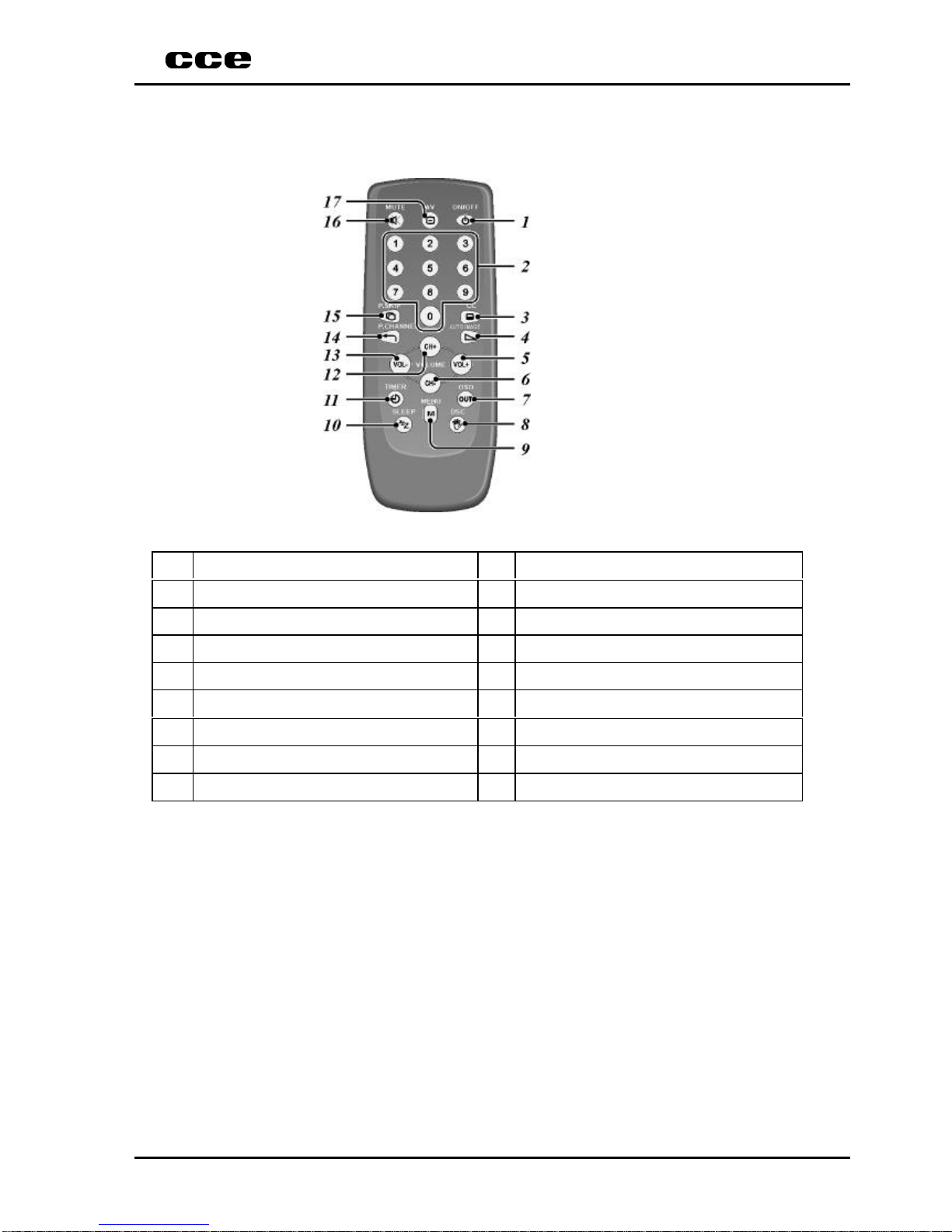
1.3 REMOTE CONTROL................................................................................................................................................4
2. TECHNICAL SPECIFICATION............................................................................................................................5
2.1 AUDIO............................................................................................................................................................................5
2.2 POWER SUPPLY........................................................................................................................................................9
2.3 FRAME GEOMETRIC............................................................................................................................................12
2.4 PURITY.........................................................................................................................................................................18
2.5 CONVERGENCE........................................................................................................................................................19
2.6 VIDEO............................................................................................................................................................................20
3. CALIBRATION GUIDE............................................................................................................................................22
3.1 IMPORTANT RECOMMENDATIONS...............................................................................................................22
3.2 DEFINITIONS OF THE REGISTERS..................................................................................................................23
3.3 GEOMETRY OF THE IMAGE...............................................................................................................................25
3.4 WHITE BALANCE.....................................................................................................................................................25
3.5 SCREEN ADJUSTMENT..........................................................................................................................................26
3.6 AGC ADJUSTMENT..................................................................................................................................................26
4. MATERIAL LIST........................................................................................................................................................27
4.1 MAIN PCB.....................................................................................................................................................................27
4.2 REMOTE CONTROL PCB......................................................................................................................................44
5. ELECTRICAL SCHEME..........................................................................................................................................46
5.1 MAIN AND REMOTE CONTROL PCB..............................................................................................................47
6. SILKTOP AND SOLDERS.......................................................................................................................................48
6.1 MAIN PCB.....................................................................................................................................................................48
6.2 REMOTE CONTROL PCB......................................................................................................................................50
7. EXPLODED VIEW .....................................................................................................................................................52
8. BLOCK DIAGRAM....................................................................................................................................................53

HPS-2007
2
1. GENERAL
1.1 Product front view
a) Front panel
a.1) Front panel functions and indications
1Remote control sensor 6 Menu
2Video input 7Channel UP
3Standby 8Volume UP
4Audio input 9Channel DOWN
5Power On/Off 10 Volume DOWN
1.2 Product back view
a) Back panel
a.1) Back panel functions and indicatioins
1Antenna input - UHF/ VHF ( 75 Ω)
2Video input
3Audio input Mono (L)

HPS-2007
3
b) Characteristics
Image Sound
Menu of Functions Function Install
VHF Channel from 2 to 13
UHF Channel from 14 to 69Channel
Cable TV Channel from 1 to 125
Product Dimensions 355X343X375 mm
c) Supply
Unit Nominal Min. Max.
Supply Voltage (FREE VOLTAGE) 120 - -
Vac 240 - -
Supply Frequency Hz 50/60 - -
Stand by W8.5 -12
Consumed Power In operation W42 -52

HPS-2007
4
1.3 REMOTE CONTROL
a.1) Remote control fucntions
1Power - On/Off 10 Sleep
2Numeric Keyborad key 11 Timer
3CC - Closed Caption 12 Channel +
4Auto Image 13 Volume -
5Volume + 14 P. Channel
6Channel - 15 P. Skip
7OSD / OUT 16 Mute
8DSC 17 AV
9Menu

HPS-2007
5
2. TECHNICAL SPECIFICATION
Procedure to check up color TV electrical parameters
2.1 Audio
2.1.1 Output power at 10% THD
1st method: antenna input connection
a) TV setup in “PP” condition (frequency and channel factory defined)
b) Apply 60dBµV signal to antenna input, modulated with white pattern in 88% and audio
signal with 1kHz frequency modulated in FM with ± 25kHz deviation.
c) Connect to the audio power amplifier output a resistive load with equivalent Ohm value of
speaker used on the tested TV.
d) Connect a AC Voltmeter/Distortion Meter to the resistive load and increase volume control
until Distortion Meter reading be 10%.
e) Measure voltage on the resistive load and calculate power through next equation:
P = (V²/R)
Where “V” is voltage in VOLTS, “R” is resistive load in OHMS e “P” is power in WATTS.
2nd method: connection through external video and audio input
a) TV setup in “PP” condition.
b) Connect a color bar generator (PAL-M system) to video input.
c) Connect an audio generator with 500mVAC level and 400Hz sinusoidal frequency to audio
input.
d) Connect to the power amplifier output a resistive load with equivalent Ohm value of
speaker used on the tested TV.
e) Connect a AC Voltmeter/Distortion Meter to the resistive load and increase volume control
until Distortion Meter reading be 10%. Measure voltage on the resistive load and calculate
power through next equation:
P = (V²/R)
Where “V” is voltage in VOLTS, “R” is resistive load in OHMS and “P” is power in WATTS.
Minimum Nominal Maximum Unit
2.00 2.90 -W

HPS-2007
6
2.1.2 Audio Residual
a) TV setup in “PP” condition.
b) Apply 60dBµV signal (frequency and channel factory defined) to antenna input modulated
with white pattern at 88% and audio signal with 1kHz frequency modulated in FM with
25kHz deviation.
c) Connect an oscilloscope to power amplifier output (connect for the speaker).
d) Adjust volume to minimum.
e) Use the oscilloscope to measure peak-to-peak voltage, in Volt peak-to-peak (Vpp).
Minimum Nominal Maximum Unit
-25 500 mVpp
2.1.3 Audio frequency response in TV’s without tone control
a) TV setup in “PP” condition.
b) Connect a color bar generator (PAL-M system) to video-in.
c) Connect to the audio input TV - an audio generator adjust to 500 mVac level, and sine
wave 1kHz.
d) Connect to the output power amplifier a resistive load with the same value of the
impedance speaker.
e) Connect na AC voltmeter over the resistive load and adjust volume control until obtain 1
Vac ).
f) Realign the audio generator to 100 Hz sine wave at the same level ( 500 mVac).
g) Read the new voltage in the resistive load and calculate the change in dB through next
equation:
A(100Hz)=20 log(VLF /VREF)
The result is defined in “Decibel units “
h) Readjust the audio generator frequency to 10 kHz at the same level.
i) Read the new voltage Vh at the resistive load and calculate the change in dB through the
next equation: A(10kHz)=20log(VHF/VREF)
Condition Minimum Nominal Maximum Unit
100Hz -4,00 0,00 +2,00 dB
10kHz -5,00 -1,00 +3,00 dB

HPS-2007
7
2.1.4 Áudio frequency response for the stereo television set with tonality control
a) Repeat the above procedures (item 1.3) for the following additional conditions:
Condition Minimum Nominal Maximum Unit
Bass control in max. position 100Hz ---dB
Treble control in the meddle.10kHz ---dB
Bass control in the min position. 100Hz ---dB
Treble control in the meddle.10kHz ---dB
Bass contr. in the meddle post.. 100Hz ---dB
Treble control int the min pos.. 10kHz ---dB
Bass contr. in the meddle pos. 100Hz ---dB
Treble contr in the max. pos.. 10kHz ---dB
2.1.5 Channel separation in Stereo reception for the stereo television set
a) TV setup in PP condition.
b) Apply a 60dBµV signal ( frequency and channel factory defined) with 88% video
modulation and audio stereo carrier modulation within the standard “MTS” (BTSC).
c) Connect an AC double voltmeter at the audio output L-R.
d) Adjust the volume control to max. and the tremble, bass and balance to middle position.
Note:
üDisconnect the speakers for more comfortable work.
e) Adjust the stereo generator for left channel only – with 30% modulation of 300 Hz sine
wave and 7.5 kHz deviation.
f) Read the Double Voltammeter value Vac corresponding of Left and Right channel and
calculate the stereo separation trough the equate:
Sep (300Hz) L
→
R = 20 log (VL/VR)
g) Adjust the stereo generator for left channel only – with 30% modulation of 3kHz sine wave
and 7.5 kHz deviation.
Sep (3kHz) L
→
R = 20 log (VL/VR)
h) Repeat the procedures e, f and g, and now select Right channel only, at the same
conditions above mentioned.
Sep(300Hz) R
→
L = 20 log (VR/VL)
Sep(3kHz) R
→
L = 20 log (VR/VL)
Condition Minimum Nominal Maximum Unit
Sep(300Hz) L→R---dB
Sep(3kHz) L →R---dB
Sep(300Hz) R→L---dB
Sep(3kHz) R→L---dB

HPS-2007
8
2.1.6 Output and distortion level of S.A.P. signal for the stereo television set.
a) TV setup in PP condition.
b) Apply a 60dBµV signal ( Frequency and channel factory defined ) with 88% video
modulation, and Stereo / S.A.P audio signal carrier in accordance of standard “MTS”
(BTSC).
c) Connect na AC volt-distortion-meter at the Left channel (pin 27 – IC604) small signal
output.
Note:
üDisconnect the speakers for more comfortable work.
d) Adjust the Stereo/SAP generator for 400 Hz sine wave and 100% modulation.
e) Active the SAP function in the Test Television.
f) Read Vac at the AC volt-distortion-meter.
g) Repeat all above procedures, connecting the volt-distortion-meter at the Right channel (pin
21 – IC604) small signal audio output.
Minimum Nominal Maximum Unit
Output Level -490 -mVAC
Distortion (THD) - - 2%
2.1.7 AM Rejection
a) TV setup in PP condition.
b) Connect at the IF sound input a FM generator adjust to 4.5 MHz modulated with 400 Hz
sine wave and +/- 25 kHz deviation and 90 dBuV level.
c) Connect na AC voltmeter in the audio detector output (after the emphasis circuit) and read
the VFM tension.
d) Connect at the IF sound input a AM generator pre-adjust to 4.5 MHz 40% modulated with
400 Hz sine wave, and 90 dBuV level.
e) Read the Vam value in the voltmeter.
AM rejection will now be calculated by the equation:
RejAM = 20 log( VFM/VAM)
Note:
üBecause this parameter is designed to define only the one circuit TV
perform, the startup conditions adjust and what’s circuits will be
supplied, it will be defined separately for each one model.
Minimum Nominal Maximum Unit
30,00 40,00 60,00 dB

HPS-2007
9
2.2 POWER SUPPLY
2.2.1 Consume
Consume
a) Connect the TV under test through a electronic wattmeter at the 234Vac/60Hz line.
b) Turn-on the TV set and apply a 60dBµV ( the preferred channel must to be defined by the
production unit), modulated with a 88% video signal white pattern, and a ±25 kHz
deviation FM carrier with a 1kHz sine wave audio signal.
c) Adjust for max. the bright, contrast and volume controls, and read the Sink Power show at
the wattmeter.
d) Active Standby mode and read again the Sink power.
e) Repeat all below procedures, connecting now the television under test to a 117Vac/60 Hz
line.
Condition Minimum Nominal Maximum Unit
117VAC “PP” -42.0 52.0 W
117VAC Stand-By -8.5 10.0 W
234VAC “PP” -42.0 52.0 W
234VAC Stand-By -9.0 12.0 W
2.2.2 Main Power Supply
a) Connect the TV set under test to 117Vac/60Hz line.
b) Turn On the TV set and apply a 60dBµV RF signal modulated by a white pattern video
signal and a 4.5 MHz +- 25 kHz deviation FM signal modulated by a 1kHz audio signal (the
preferred channel will be defined by the local unit).
c) Adjust the TV to a “PP” condition.
d) Utilizing a electronic DC voltmeter ( over 10 M input impedance), read the next point in the
power supply:
Condition Test Point Minimum Nominal Maximum Unit
“PP” 117VAC +B 103V (Cathode of D807) 102.00 103.00 104.00 VDC
“PP” 117VAC +B 16V (Cathode of D808) 14.00 15.50 16.50 VDC

HPS-2007
10
2.2.3 Main Power Supply Regulation with fluctuation of the line
a) Repeat the procedure of the item 2.2 when the television is connected to the electric net
with 100VAC/60Hz and also 240VAC/60Hz.
Condition Test Point Minimum Nominal Maximum Unit
“PP” 240VAC +B 103V (Cathode of D807) 102.00 103.00 104.00 VDC
“PP” 240VAC +B 16V (Cathode of D808) 14.00 15.50 16.50 VDC
Condition Test Point Minimum Nominal Maximum Unit
“PP” 100VAC +B 103V (Cathode of D807) 102.00 103.00 104.00 VDC
“PP” 100VAC +B 16V (Cathode of D808) 14.00 15.50 16.50 VDC
2.4 Auxiliary power supply from Fly Back Transformer.
a) Connect the TV under test to a 117 Vac/60 Hz line.
b) Turn On the TV set and apply a 60dBµV RF signal modulated by a white pattern video
signal and a 4.5 MHz +- 25 kHz deviation FM signal modulated by a 1kHz audio signal
(Frequency and channel factory defined).
c) Adjust the TV to a “PP” condition.
d) Utilizing a electronic DC voltmeter (over 10 M input impedance), read the auxiliary power
supply from Fly-Back transformer :
e) Read the RMS voltage apply to the CRT heat., Utilizing a true RMS voltmeter.
f) When exist, read the auxiliary wind Peak to peak voltage, utilizing an oscilloscope.
Condition Test Point Minimum Nominal Maximum Unit
“PP” 117VAC E+12V (Cathode do D402) +11.00 +12.00 +13.00 VDC
“PP” 117VAC E-12V (Anode do D403) -11.00 -12.00 -13.00 VDC
“PP” 117VAC E180V (Anode do D404) 165.00 175.00 185.00 VDC
“PP” 117VAC Heater (RMS) (Pins 5 and 4 of
V901) 5.70 6.30 6.90 VRMS

HPS-2007
11
2.2.5 High Voltage (EHT)
a) Connect a DC voltmeter to the resistor wired to the Fly Back ABL pin ( the position and
value of this resist is defined by each model.
b) Connect a high voltage electronic DC voltmeter ( over 1G impedance) in the electronic tube
high voltage plug.
c) Adjust the bright, color and contrast controls to minimum and read the high voltage E.H.T.
(IAmin).
d) Adjust the bright control to the maximum position, contrast control to the maximum position
and monitoring the voltage through the ABL resistor, adjust the bright control until the DC
voltage reached the specific value. The anode electric current will now be define by the
following equation:
IA=(VABL/RABL)
Read the high voltage E.H.T. in this conditions ( IAmin.).
Condition Minimum Nominal Maximum Unit
IAmin. 22.30 23.50 24.75 kVDC
IA=1mA 20.60 21.70 22.85 kVDC
2.2.6 Dielectric Rigid
Adjust the HI_POT equipment to 1500 Vac voltage, and the desired test current, in accordance
with the below specification table. When the TV set have a power switch, make sure that this
switch stay in the ON mode. Connect the ground terminal of the test equipment in both pins of the
line cord TV, and apply the HI-POT terminal ( 1.5KV) in every extern metal parts of the TV under
test for one minute. In this condition the electric current must be equal or inferior that shown in the
below specific table
Condition Minimum Nominal Maximum Unit
1500VAC - - 2,00 mAAC

HPS-2007
12
2.3 Frame geometric
2.3.1 Wide and height of the frame
Preparation:
a) Connect the receiver under test to a 117VAC line.
b) TV setup in PP condition.
c) Apply to the antenna input a 60dBµV signal – 88% modulated with the CROSSHATCH
pattern
(The preferred channel will be defined by the fabric unit )
d) Adjust the contrast control so that average Iabl is the same to 750µA (Iabl=750µA).
IABL=(VABL/RABL)
e) Observe the pattern image and make a block count in the horizontal and vertical direction.
Minimum Nominal Maximum Unit
Height (PAL-N) 10,07 10,60 11,13 Blocks
Wide (PAL-N) 13,96 14,70 15,43 Blocks
Height(PAL-M) 10,26 10,80 11,34 Blocks
Wide (PAL-M) 14,15 14,90 15,64 Blocks

HPS-2007
13
2.3.2 Frame centralization
Preparation:
a) Connect the receiver under test to a 117 VAC line.
Turn On the TV and position the bright and contrast control to the maximum, and the
saturation and volume controls to the minimum position. Wait for a pre-heating period.
b) Apply a CIRCLE pattern 60dBµV signal with 88% modulation ( The preferred channel will
be define by the fabric unit ).
c) Position to “nominal” the bright and contrast controls.
d) For the next reading, please observe the figure B.
e) Observe the image and make the measures (in centimeters) of the distances a, b, c and d.
f) Apply the following formula to calculate the horizontal centralization.
(a/b)-(d/c)
g) Observe the image and make the measures (in centimeters) of the distances p, q, r and s.
h) Apply the formula to calculate the vertical centralization.
(p/q)-(s/r)
Minimum Nominal Maximum Unit
|(a/b)-(d/c)| -0,00 0,10
|(p/q)-(s/r)| -0,00 0,20

HPS-2007
14
2.3.3 FRAME ASPECT RELATED
a) Connect the receiver under test to a 117VAC line.
Turn on the TV and adjust bright and contrast control to max. position, saturation and
volume to min. Position. Wait for the heat period.
b) Apply to the antenna input a 60dBµV level signal with 88% modulated PHILIPS pattern
(Frequency and channel factory defined)
c) Adjust bright and contrast control to nominal position
d) For the next reads, please utilizes figure C for reference.
e) Observe the screen pattern and check the distances a, b, c, d (in centimeters)
f) Apply the formula:
M = (a + b + c + d) / 4, and verify the proportion a/M, b/M, c/M e d/M.
Check for systems PAL-M and PAL-N
Minimum Nominal Maximum Unit
a/M 0,95 1,00 1,05
b/M 0,95 1,00 1,05
c/M 0,95 1,00 1,05
d/M 0,95 1,00 1,05

HPS-2007
15
2.3.4 Horizontal Linearity
a) Connect the receiver under test in 117VAC line.
Turn on the TV and adjust bright and contrast control to max. position, saturation and
volume to min. Position. Wait for the heat period.
b) Apply to the antenna input a 60dBµV level signal with 88% modulated PHILIPS pattern
(Frequency and channel factory defined)l
c) Adjust bright and contrast control to nominal position
d) For the next reads, please take references by figure D.
e) Observe the screen pattern and check the distances An - 14 blocks (in centimeters)
f) Calculate the middle distances through blocks
M = An/14.
Horizontal deviation between major blocks (DHM)
Read first the 14 blocks wide (from b1 to b14) and select the biggest read (bmax) for calculate
the deviation: DHM= bmáx/M
Minor Horizontal deviation between blocks (DHm)
Read first the 14 blocks wide (from b1 to b14) and select the smallest read (bmin) for calculate
the deviation: DHm= bmín/M
(*)Check for signals PAL-M and PAL-N
PAL-M Minimum Nominal Maximum Unit
DHM-1,10 1,30
DHm0,70 0,95 -
PAL-N Minimum Nominal Maximum Unit
DHM-1,10 1,30
DHm0,70 0,95 -

HPS-2007
16
2.3.5 Vertical Linearity
a) Connect the receiver to a 117VAC line
Turn on the TV and adjust bright and contrast control to max. position, saturation and
volume to min. Position. Wait for the heat period (please see the specification for this
model).
b) Apply to the antenna input a 60dBµV level signal with 88% modulated PHILIPS pattern
(Frequency and channel factory defined).
c) Adjust bright and contrast control to nominal position
d) For the next reads, please take references by figure E
e) Observe the screen pattern and check the distances X –(in centimeters)
f) Calculate the middle distances through blocks:
amedium=X/10.
Major vertical deviation between blocks (DVM).
Read first the 10 blocks height (from a1 to a10) and select the biggest of them (amax) for
calculate the deviation :
DVM= amax/amedium
Minor vertical deviation between blocks (DVm)
Read first the 10 blocks height (from a1 to a10) and select the smallest of them (amin) for
calculate the deviation:
DVm= amin/amedium
(*)Check for signals PAL-M and PAL-N
PAL-M Minimum Nominal Maximum Unit
DVM-11,40
DVm0,60 1-
PAL-N Minimum Nominal Maximum Unit
DVM-11,40
DVm0,60 1-

HPS-2007
17
2.3.6 Pin-Cushion & Shape of Raster
a) Connect the receiver to a 117VAC line.
Turn on the TV and adjust bright and contrast control to max. position, saturation and
volume to min. Position. Wait for the heat period (please see the specification for this
model).
b) Apply to the antenna input a 60dBµV level signal with 88% modulated “CROSSHATCH”
pattern (Frequency and channel factory defined)l
c) Turn the face tube to West/Lest orientation
d) Adjust bright and contrast control to “PP” position
e) For the next reads, please take references by figure F ( distances in millimeters)
f) Observe the screen pattern, to calculate:
Top-Bottom = 2(c1 + c2)/(AD + BC) X 100
Left-Right = 2(d1 + d2)/(AB +CD) X 100
(*) Check for signals PAL-M and PAL-N
Minimum Nominal Maximum Unit
TOP-BOTTOM - - 1,50 %
LEFT-RIGHT - - 2,00 %

HPS-2007
18
2.4 Purity
a) Connect the receiver to a 117VAC line
Turn on the TV and adjust bright to nominal position and contrast control to min. position,
saturation and volume to min. position.
b) Apply to the antenna input a 60dBµV level signal with 88% modulated “WHITE” pattern
(Frequency and channel factory defined)l
c) Wait for pre-heating period (30 minutes)
d) Degauss the device appropriated.
e) Increment the contrast controls to max. position, and wait for 3 minutes
f) At a distance of 5 times the height of the screen, observe that no color dirty may appears.
g) Repeat this procedures now utilizing a red pattern.
Note:
üIf the receiver is moved during the test procedure, always degauss
again the device

HPS-2007
19
2.5 Convergence
a) Connect the receiver to a 117VAC line
Turn on the TV and adjust bright and contrast control to max.. position, saturation and
volume to min. position. Wait for pre-heating period ( please see specification for each
model)
b) Apply to the antenna input a 60dBµV level signal with 88% modulated “CROSSHATCH”
pattern (Frequency and channel factory defined)l
c) Turn the face tube to West/Lest orientation
d) Degauss the device properly
e) Adjust bright and contrast control to minimum position
M1
M2
M3
f) For the next reads, please take references by figure G ( distances in millimeters)
(mm)
M1 60
M2 120
M3 85
(*) Apply for signals PAL-M and PAL-N.
PONTO X, Y LIMITES (mm)
a0.4
b, c 0.9
d, e 0.9
f, g, h, j’ 1.4
f’, g’, h’, j 1.2
k, l, m, n 1.0
s, t, u, v 0.8
Other manuals for HPS-2007
1
Table of contents
Other CCE TV manuals