HPS-2971
3.1.5 Channel separation in Stereo reception for the stereo television set
a) TV setup in PP condition.
b)Apply a 60dBmV signal (frequency and channel factory defined) with 88%
video modulation and audio stereo carrier modulation within the standard
“MTS” (BTSC).
c) Connect an AC double voltmeter at the audio output L-R.
d)Adjust the volume control to max. and the tremble, bass and balance to
middle position.
Note:
üDisconnect the speakers for more comfortable work.
e) Adjust the stereo generator for left channel only –with 30% modulation of
300 Hz sine wave and 7.5 kHz deviations.
f) Read the Double Voltammeter value Vac corresponding of Left and Right
channel and calculate the stereo separation trough the equate:
Sep (300Hz) L→R=20 log (VL/VR)
g)Adjust the stereo generator for left channel only –with 30% modulation of
3kHz sine wave and 7.5 kHz deviation.
Sep (3kHz) L→R=20 log (VL/VR)
i) Repeat the procedures e, f and g, and now select Right channel only, at the
same conditions above mentioned.
Sep(300Hz) R→L=20 log (VR/VL)
Sep(3kHz) R→L=20 log (VR/VL)
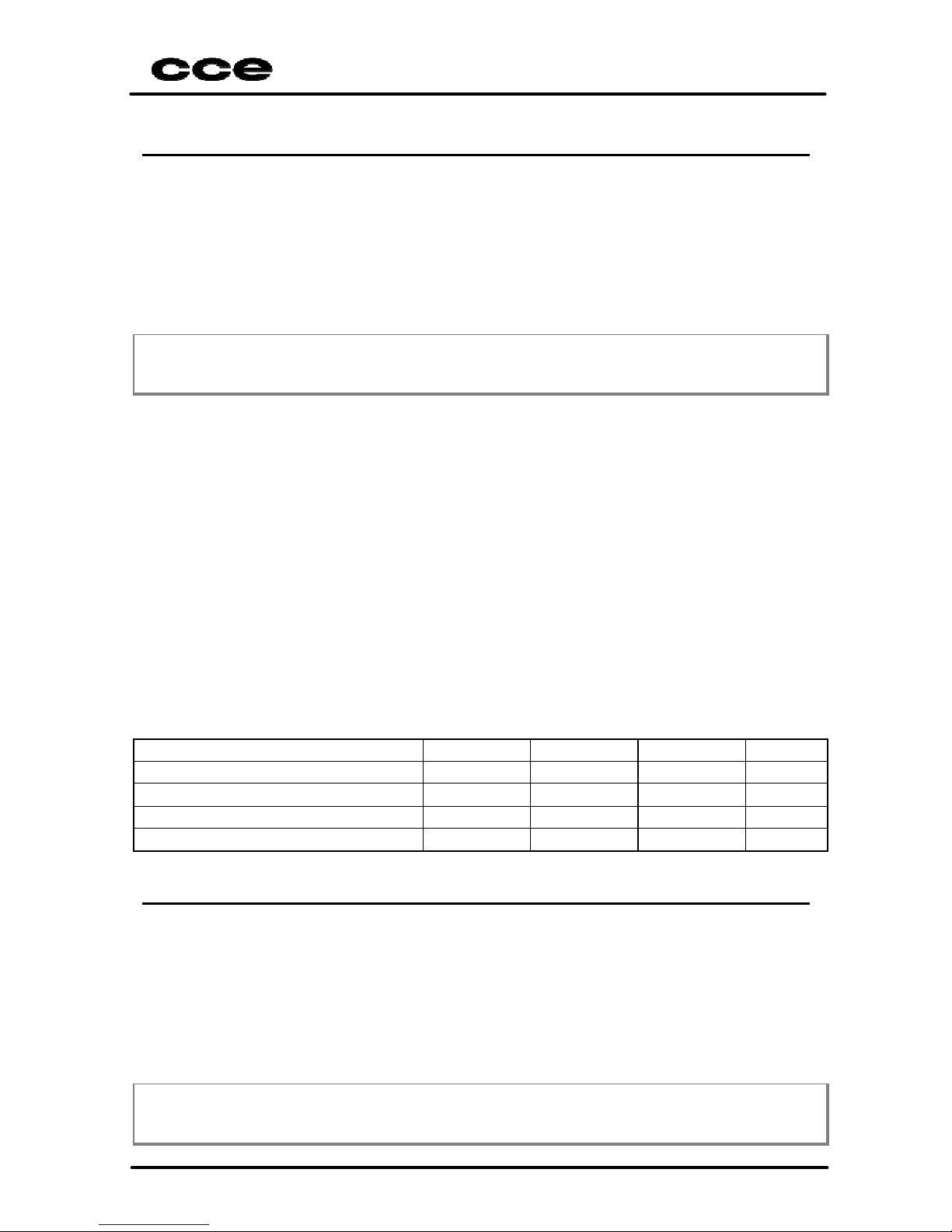
Condition Minimum Nominal Maximum Unit
Sep(300Hz) L →R12,00 --dB
Sep(3kHz) L→R12,00 --dB
Sep(300Hz) R→L12,00 --dB
Sep(3kHz) R→L12,00 --dB
3.1.6 Output and distortion level of S.A.P. signal
a) TV setup in PP condition.
b)Apply a 60dBµV signal (frequency and channel factory defined) with 88%
video modulation, and Stereo / S.A.P audio signal carrier in accordance of
standard “MTS” (BTSC).
c) Connect an AC volt-distortion-meter at the Left channel.
d)Adjust the volume control to max. and the tremble, bass and balance to
middle position.
Note:
üDisconnect the speakers for more comfortable work.