10
Notizie generali
Per un buon funzionamento delle automazioni in oggetto, il cancello da automatizzare dovrà rispondere alle seguenti
caratteristiche:
- buona robustezza e rigidità
- ogni anta deve avere una sola cerniera (eventualmente eliminare le superue all’atto dell’automazione)
- le cerniere devono presentare giochi minimi e permettere che le manovre manuali siano dolci e regolari
- in posizione di chiusura le ante devono combaciare fra loro per tutta l’altezza.
1. Caratteristiche generali
Sistema a scomparsa totale che non altera l’estetica del cancello.
Semplice ed afdabile può essere installato su qualsiasi cancello a battente no a max. 3.5 m per anta (max 3m per
versione TERRA FC-V).
Il movimento è silenzioso e regolare grazie ad un sistema di leve che adegua la velocità alle varie fasi della manovra.
Il motoriduttore, interamente a bagno d’olio, non permette l’inltrazione d’acqua o la formazione di condensa che po-
trebbero compromettere irrimediabilmente la funzionalità del motore.
Non necessita di elettroserrature in quanto il sistema irreversibile assicura il blocco delle ante.
L’installazione è di facile esecuzione; infatti, una volta interrata la cassa, il motoriduttore viene ssato con viti e dadi in
acciaio inox.
Lo sblocco per la manovra manuale avviene mediante chiave speciale in dotazione.
Le casse di fondazione sono in lamiera zincata a caldo per garantire una maggiore durata nel tempo.
Con l’applicazione del dispositivo 180TER-FC si ottiene un’apertura a 180° (per ante con lunghezza non superiore a 2
m). Lo stesso 180TER-FC può essere adottato come soluzione per l’automazione di passaggi speciali.
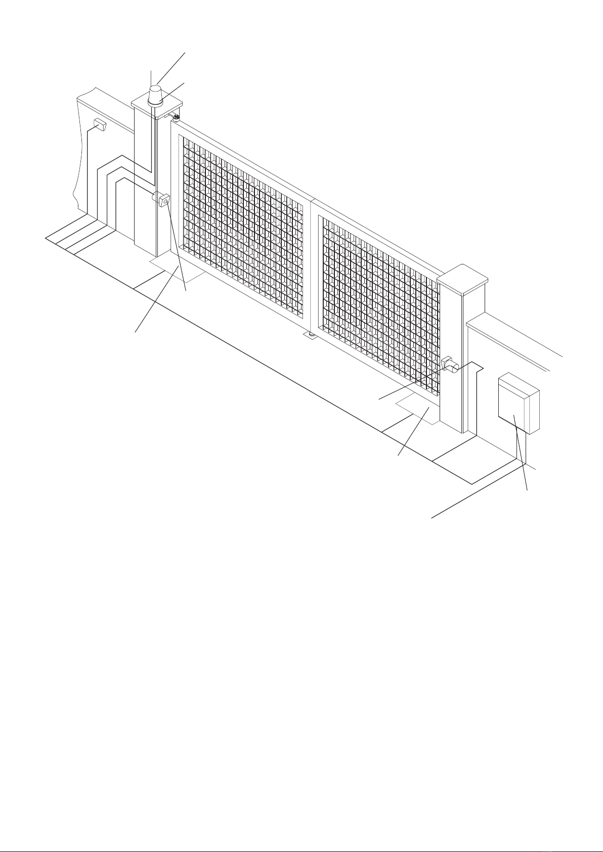
2. Arresti meccanici (g. 1)
Il cancello da automatizzare deve disporre di arresto meccanico sia in apertura che in chiusura, in quanto il TERRA
FC-L/TERRA FC-V non dispone di necorsa elettromagnetici. E' comunque disponibile come accessorio opzionale il
kit necorsa TFC di rapida installazione e regolazione.
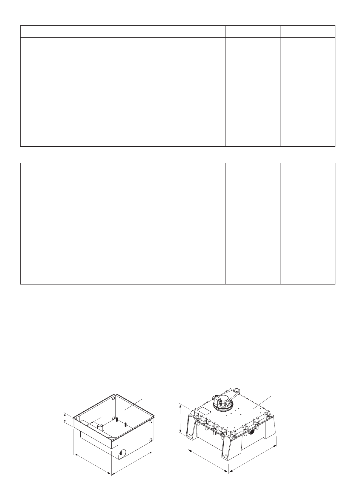
3. Posa della cassa di fondazione
Effettuare lo scavo secondo indicazioni di g. 2 prevedendo un drenaggio per l’acqua e un arrivo cavi su uno dei 4
angoli dove esistono apposite forature (g. 3).
Cementare la cassa avendo cura di controllarne l’orizzontalità tramite livella.
4. Fissaggio del motoriduttore
4.1 Fissare il motoriduttore con n° 4 dadi esagonali M10 inox (in dotazione) sulle viti sporgenti dalla cassa interrata.
N.B.: Nella cassa sono presenti 8 viti; utilizzare quelle rispondenti alle esigenze seguendo le istruzioni di g. 4.
4.2 Saldare il gruppo di traino all’anta secondo g. 5.
4.3 Posizionare l’anta in sede avendo cura di interporre la sfera tra il perno della cassa di fondazione ed il gruppo di
traino (Fig.6).
4.4 Collegare il gruppo di traino con la staffa del motore tramite la leva di collegamento (Fig.7).
4.5 Con l'anta in appoggio sul fermo di arresto di chiusura, regolare la vite V di Fig.7 ad una distanza di 1/2mm dalla
leva di collegamento (solo nel caso di montaggio standard).
4.6 E disponibile come accessorio il fermo meccanico per apertura a 90° da posizionare nell'apposita sede sulla staffa
di traino, come indicato in Fig.7
4.7 Prima di serrare i dadi M10, controllare che il motoriduttore sia ben appoggiato al fondo della cassa, altrimenti
spessorare dove richiesto, tenendo presente che il motoriduttore deve essere in piano (vericare ciò tramite livella).
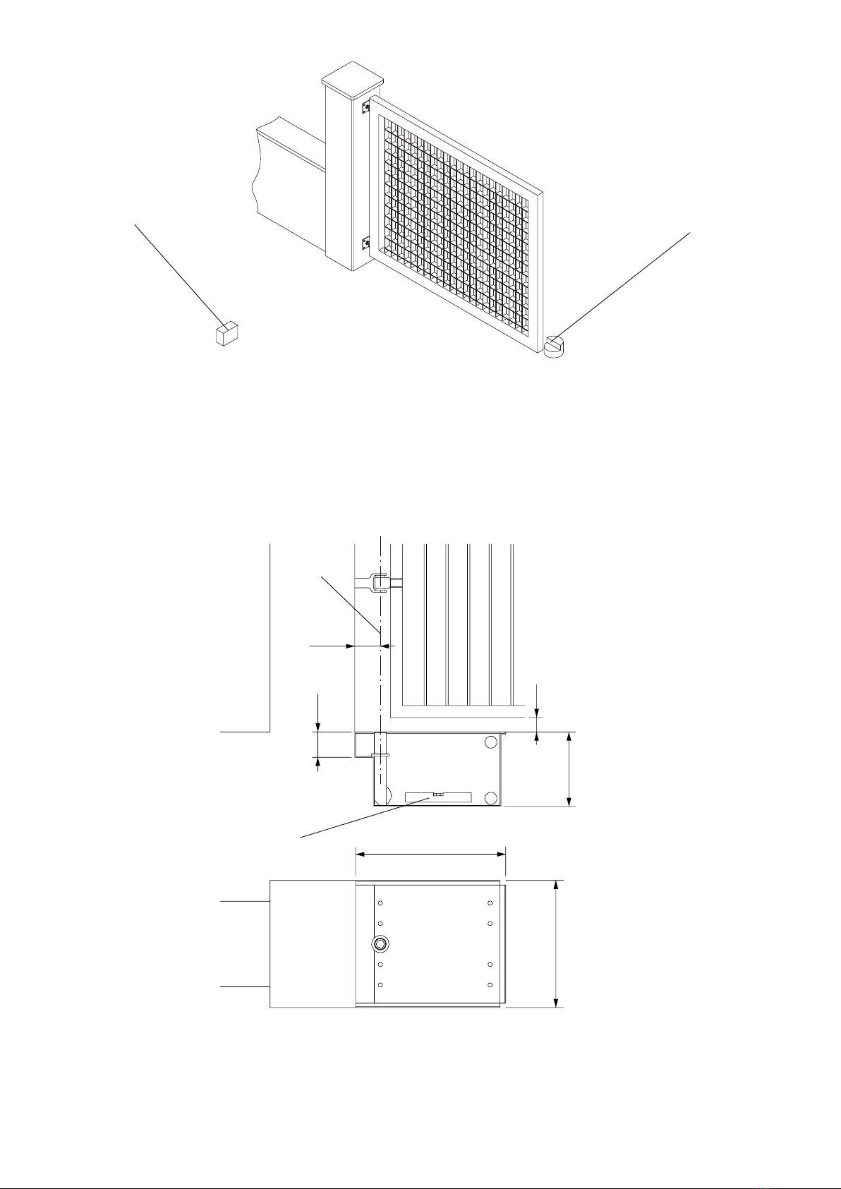
5. Apertura a 110° (g. 8)
Nella posa delle casse per apertura a 110° art. 110 TER, calcolare che la quota X tra perno e spigolo del portante sia
tale da permettere la rotazione tenendo conto dello spessore del portone Y.
6. Apertura a 180°
Usufruendo della cassa 110 TER, si può realizzare anche l’apertura a 180° tramite l’apposito dispositivo art. 180 TER-
FC. Tale soluzione è consigliata per lunghezze anta no a 2 m; si può utilizzare anche per lunghezze maggiori, ma il
funzionamento diventa meno dolce e regolare.