Ultra excellent 3
Wichtig: Tor auf Funktion sowie Leichtgängigkeit
prüfen und ggf. einstellen. Die Federspannung des
Tores muss so eingestellt sein, dass es ausbalanciert ist und
sich von Hand leicht, gleichmäßig und ruckfrei öffnen und
schließen lässt.
• Genormte und geeignete Schutzkontaktsteckdose ca. 10 -
50 cm neben Befestigungsposition Antriebskopf.
(Absicherung siehe technische Daten)
• Torantrieb nur in trockene Garagen einbauen.
Montagesatz für Toranschluss am zu montierenden Tortyp
bereithalten bzw. entsprechend dessen Anleitung montieren.
Siehe Hinweise zur Montage ab Seite 121.
Montageschritt D, Seite 122:
• 1. Spannmutter des Zahnriemens anziehen bis
Zahnriemen nicht mehr in der Führungsschiene aufliegt
(entspricht Maß X).
• 2. Zahnriemenspannung mittels Spannmutter
entsprechend der Torantriebslänge (Maß B) erhöhen.
Nach abgeschlossener Inbetriebnahme Lichtscheibe wieder
einbauen. Siehe Abschnitt L, Seite 127.
• Tor von Hand langsam öffnen bis Schlitten hörbar
einrastet.
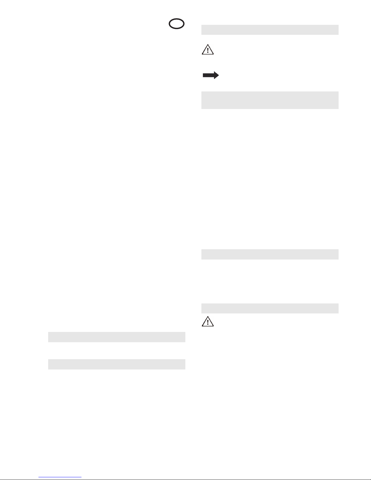
• Netzanschluss herstellen, LED „Netzbetrieb bereit“ (D)
leuchtet.
ACHTUNG: Beim Einlernen des Torantriebs
besteht kein Schutz durch Kraftabschaltung!
Hinweis: Einlernen nur bei Erstmontage oder nach einem
Reset des Torantriebs möglich. Während dem Lernvorgang
keine Tasten drücken.
Vorbereitung: Tor am Torantrieb ankoppeln.
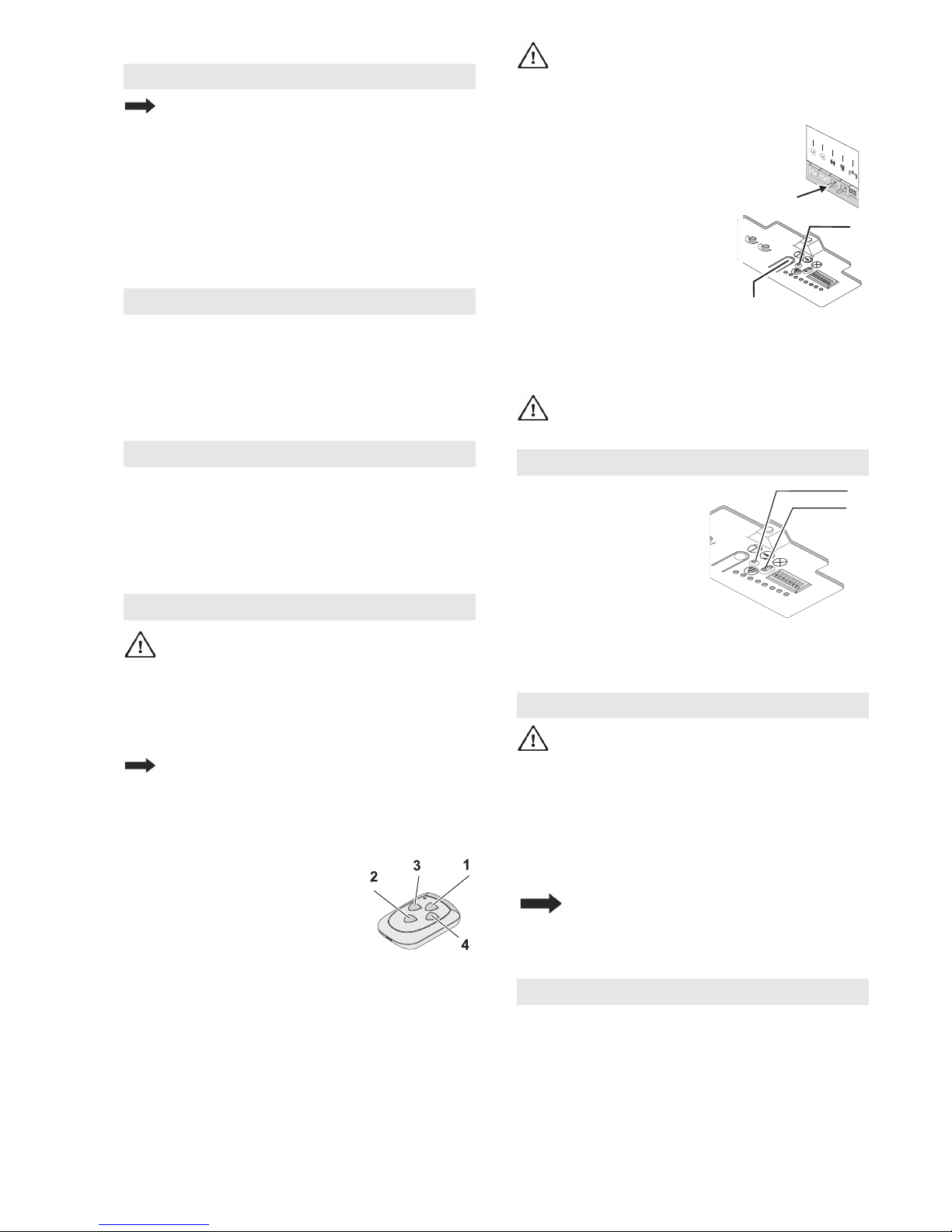
Einlernen mit Handsender
Der Handsender weist zum Zeitpunkt der Auslieferung
und nach einem Reset des Torantriebes folgende
Funktionen auf:
• 1 Totmann-Betrieb und Feineinstellung "AUF"
• 2 Totmann-Betrieb und Feineinstellung "ZU"
• 3 und 4 Bestätigung (Abspeichern)
Nach dem Einlernen des Torantriebs
wird Taste 1 zur Fernsteuerung
verwendet, die anderen Tasten können
zur Ansteuerung weiterer, baugleicher
Torantriebe oder Funkempfänger
eingesetzt werden.
Einlernen
• Taste 1 drücken und gedrückt halten, das Tor bewegt sich
in Öffnungsrichtung.
• Wenn gewünschte Position Endlage „AUF" erreicht ist,
Taste 1 loslassen. (Korrektur mit Taste 2 möglich)
• Taste 3 einmal kurz drücken, Lernvorgang: Der Torantrieb
lernt automatisch „Endlage AUF / ZU“ und Kräfte der
„Wege AUF / ZU“ ein. Torantriebsbeleuchtung blinkt
rhythmisch.
Der Lernvorgang ist abgeschlossen, wenn das Tor offen ist
und die Torantriebsbeleuchtung leuchtet.
Kraftabschaltung gemäß Kapitel
Sicherheitsüberprüfung überprüfen.
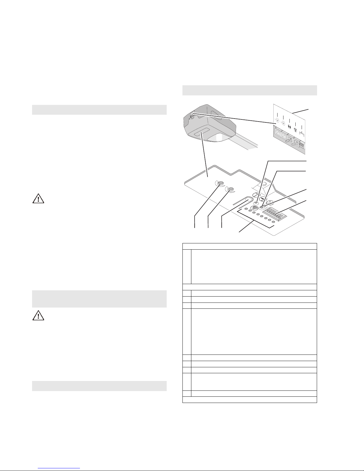
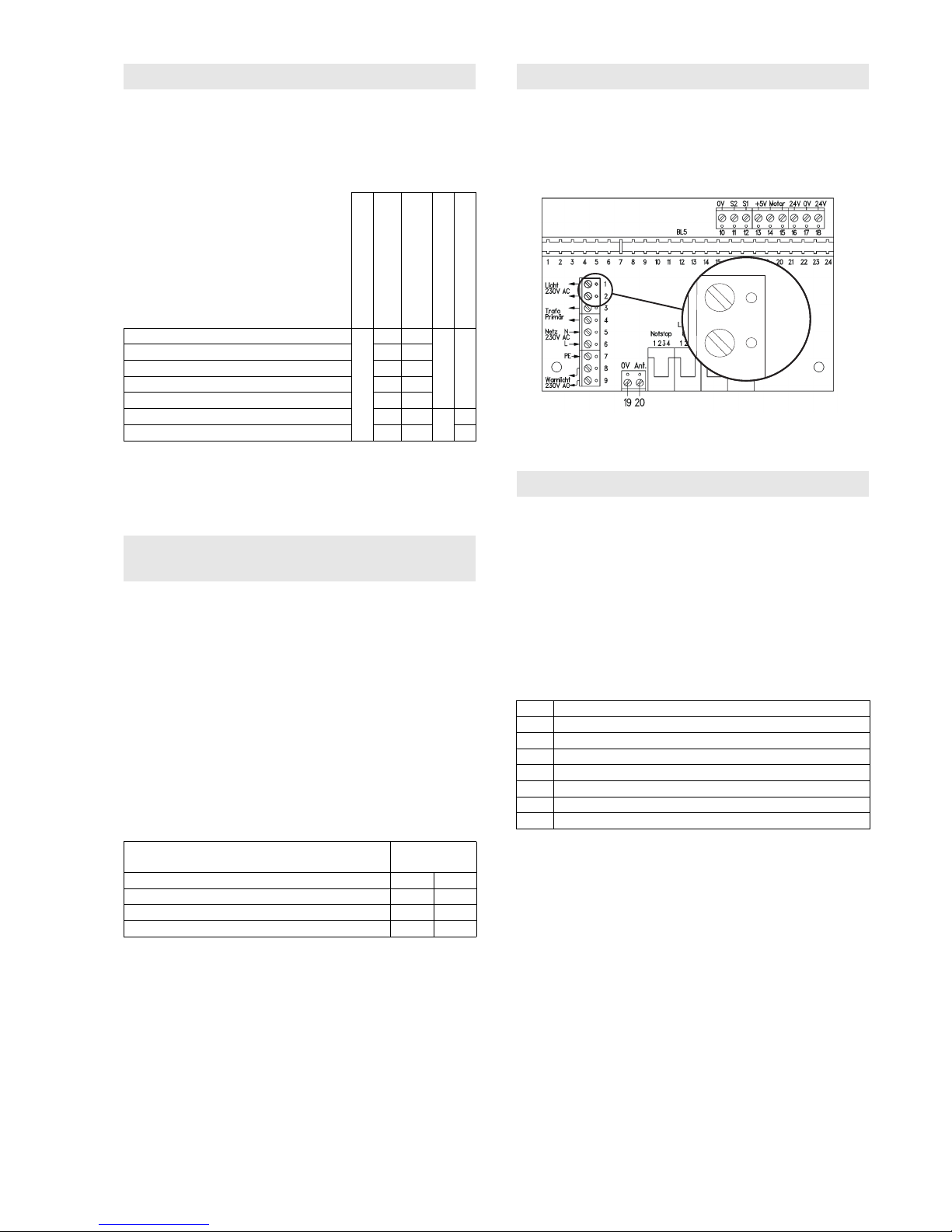
Einlernen ohne Handsender
Am Torantrieb:
• Westernstecker 3 A abziehen.
• Taster „Impuls“ H drücken und
gedrückt halten, das Tor bewegt
sich in Öffnungsrichtung.
• Wenn gewünschte Position
Endlage „AUF“ erreicht ist, Taster
„Impuls“ H loslassen.
• Westernstecker 3 A wieder
einstecken. Korrektur mit Taster
„Impuls“ H möglich)
• Taster "Programm" B drücken,
Lernvorgang: Der Torantrieb lernt
automatisch „Endlage AUF / ZU“
und Kräfte der „Wege AUF / ZU“ ein.
Torantriebsbeleuchtung blinkt rhythmisch.
Der Lernvorgang ist abgeschlossen, wenn Tor offen ist und
die Torantriebsbeleuchtung leuchtet.
Kraftabschaltung gemäß Kapitel
Sicherheitsüberprüfung überprüfen.
Handsender einlernen:
• Taster "Programm" B
drücken, LED C blinkt 1-mal
• Innerhalb 20 Sec. eine noch
nicht eingelernte Taste am
Handsender drücken, LED C
leuchtet, das Einlernen ist
abgeschlossen.
(Alle) Handsender löschen
• Taster "Programm" B >5 Sec. drücken, LED C blinkt
zunächst langsam, anschließend schnell und erlischt. Alle
eingelernten Handsender sind gelöscht.
VORSICHT: Sorgloser Umgang mit dem Torantrieb
kann zu Verletzungen oder Sachbeschädigungen
führen. Grundlegende Sicherheitsregeln beachten:
Beim Öffnen und Schließen des Tores die Schwenkbereiche
innen und außen freihalten. Kinder fernhalten.
Die Torbewegungen können über den mitgelieferten
Handsender oder optional anschließbare Schaltelemete (z.B.
Wandtaster) ausgelöst bzw. gestoppt werden.
Externe Zusatzeinrichtungen (z.B. Not-Stopp) können
angeschlossen werden.
Der Antrieb darf nicht ohne angekoppeltes Tor
betrieben werden. Die Elektronik würde
dadurch falsche Kraftwerte einlernen.
Funktionsstörungen können die Folge sein.
Motorkrafteinstellung
Die Werkseinstellung muss im Normalfall nicht geändert
werden. In dieser Stellung sollte ein leichtgängiges Tor
einwandfrei laufen, es darf ohne Einwirkung eines
Hindernisses nicht stehen bleiben oder seine Laufrichtung
ändern. Bevor eine andere Einstellung vorgenommen wird,
muss das Tor auf Leichtgängigkeit und Funktion überprüft
und ggf. besser eingestellt werden.
Einbauvorbereitung
Montage
Inbetriebnahme
Torantrieb einlernen
Handsender einlernen / löschen
Bedienung
Einstellungen / Zusatzfunktionen