Cellar Cool cx2200 User manual

CX SERIES
OWNER’S MANUAL
cx2200
cx3300
cx4400
cx8800

Copyright © 2017. CellarCool. All rights reserved.
CellarCool copyrights this manual, the product design, and the design concepts, with all rights reserved. Your rights with
regard to the hardware and manual are subject to the restrictions and limitations imposed by the copyright laws of the USA.
Under copyright laws, this manual may not be copied, reproduced, translated, transmitted, or reduced to any printed or
electronic medium or to any machine-readable form, for any purpose, in whole or in part, without the written consent of
CellarCool.
Every effort has been made to ensure that the information in this manual is accurate. CellarCool is not responsible for
printing or clerical errors.
CellarCool reserves the right to make corrections or improvements to the information provided and to the related hardware
at any time, without notice.
Vinothèque and CellarCool are registered trademarks, and ECE is a trademark of CellarCool. All rights reserved.
Mention of third-party products is for informational purposes only and constitutes neither an endorsement nor a
recommendation. CellarCool assumes no liability with regard to the performance or use of these products.
We manufacture, test and certify 100% of our wine cooling units in
the USA. By sourcing the best components and closely controlling our
manufacturing processes, we can assure the highest-quality,
lowest defect manufacturing rates in the industry.
Conforms to ANSI/UL Std 427
Certied to CAN/CSA Std C22.2 No. 120

TABLE OF CONTENTS
Introduction ...............................................2
Before You Start ...........................................3
Receiving & Inspecting The Unit ...........................4
Quick Reference Guide
Unit.....................................................5
Specications ...........................................6
Preparing the Wine Cellar..................................7
Installation
Airow Control ..........................................9
Preparing the Installation Location..................... 10
Preparing the Unit for Installation ...................... 11
Installing the System .................................. 11
Drain Line ............................................. 13
System Operation. . . . . . . . . . . . . . . . . . . . . . . . . . . . . . . . . . . . . . . . 14
Controller Functions ..................................... 15
Wiring Schematics
cx2200 & cx3300 ...................................... 17
cx4400 ................................................ 18
cx8800 ................................................ 19
Troubleshooting Guide .................................. 21
Maintenance Schedule .................................. 23
Technical Assistance & Accessories ...................... 24
Installation Terms & Conditions ......................... 25

Page 2 | 1-855-235-5271 CX 040418
INTRODUCTION
Customer Service
Thank you for purchasing a CellarCool cooling system. We strive to provide the highest-quality products and the best
possible customer service. If you have any questions about your system, please call us at 1-800-343-9463 or visit
cellarcool.com.
Using the Manual
This manual is intended to assist in the proper maintenance of the cooling system. In order to ensure the longevity
of your cooling unit, the equipment should be installed correctly and have a proper care and maintenance schedule.
Please read and review this manual carefully and keep it for future reference.
What is the CellarCool Cooling Unit?
The CellarCool cooling unit is a specialized refrigeration unit designed for one purpose only: to maintain the optimal
temperature and humidity levels conducive to the proper storage and aging of fine wines. It is a self-contained cooling
unit designed to be used as a forced-air through-the-wall unit.
How Does the CellarCool Cooling Unit Work?
The CellarCool cooling unit is specially designed for the use and application to maintain optimal conditions for wine
storage and aging. The unit is fully self-contained and can be installed as a through-the-wall application with
the ability to duct the exhaust air. The unit is temperature-controlled via an air sensor.
Temperature Setting
The CX Series unit can be set at any temperature within the acceptable wine-aging range of 50°F to 67°F. It is designed
to cool 30°F cooler than the ambient temperature of the space to which it is exhausting.

www.cellarcool.com | Page 3
CX SERIES
This guide is meant to serve as a quick reference for installation of the CellarCool unit. The remainder of this owner’s manual will
provide more detailed information and instructions.
Upon receiving the CellarCool cooling unit:
1. Inspect the unit before installation. If damage is found, please contact your distributor or CellarCool Customer Service at
1-800-343-9463.
2. The unit should remain in an upright position for 24 hours prior to operation.
3. The CellarCool unit requires a dedicated 115-volt, 20-amp circuit. Use a surge protector with the CellarCool unit. Do not
use a GFI (ground fault interrupter) line.
4. The unit is designed to gently cool down the temperature of the cellar over time by cycling cooler air throughout. Test the
unit prior to installation.
5. You are required to install a drain line to remove condensation from the unit.
6. The CellarCool unit is intended for use in properly designed and constructed wine cellars. Hire a professional wine storage
consultant with a valid contractor’s license to build your wine cellar.
Never try to open the CellarCool unit, repair it yourself, or use a service company
without CellarCool’s authorization. This will void your warranty.
If you encounter a problem with your CellarCool unit, please refer to the Troubleshooting Guide. If you have any further questions or
concerns, or need technical assistance, please contact CellarCool Customer Service at 1-800-343-9463. Please be sure all testing has
been completed prior to contacting Customer Service. Please have your results ready for your representative.
BEFORE YOU START

Page 4 | 1-855-235-5271 CX 040418
NOTE: CellarCool units are manufactured in the USA and tested prior to shipment.
Please leave the CellarCool unit in its original box until you are ready for installation. This will allow you to move the product
safely without damaging it. When you are ready to remove the product from the box, refer to the installation instructions.
TIP: Save your box and all packaging materials. They provide the only safe means of transporting/shipping the unit.
cx3300 and cx4400
Accessory kit #1:
•(1) CellarCool CX Series owner’s
manual
•(2) Mounting flanges
•(2) Magnetic deflectors for airflow
control
•(18) Anti-microbial pan tabs
•(1) Drain line brush
Accessory kit #2:
•(8) #6 x 1¾" hex washer head screws
• (6) ½" pan-head screws
•(1) ½" ID plastic tubing (10 feet)
•(2) Pieces of insulation foam (20")
•(2) Pieces of insulation foam (17")
RECEIVING AND INSPECTING THE UNIT
Upon receiving your CellarCool unit:
•Lift only at the designated hand-hold locations on the shipping container, or fully support the unit from underneath. A
shipment may include one or more boxes containing accessories.
•Inspect the packaging for any obvious signs of damage or mishandling before opening the container.
•Note any discrepancies or visual damage on the bill of lading before signing.
•Place the box containing the CellarCool unit on a tabletop to prepare it for testing prior to installation.
•Sit unit upright for 24 hours.
•Review the packing slip to verify the package’s contents.
•Check the model number to ensure it is correct.
•Check that all factory options ordered are listed.
•Check the box for the following:
Electrical Outlet
Power surges and spikes can damage sensitive electrical equipment. CellarCool recommends plugging the unit into a surge
protector or power conditioner in order to protect your system. As outlined in our terms and conditions, power surges and spikes
are not covered under warranty.
Do not use a GFI (ground fault interrupter) with this product.
Testing Unit
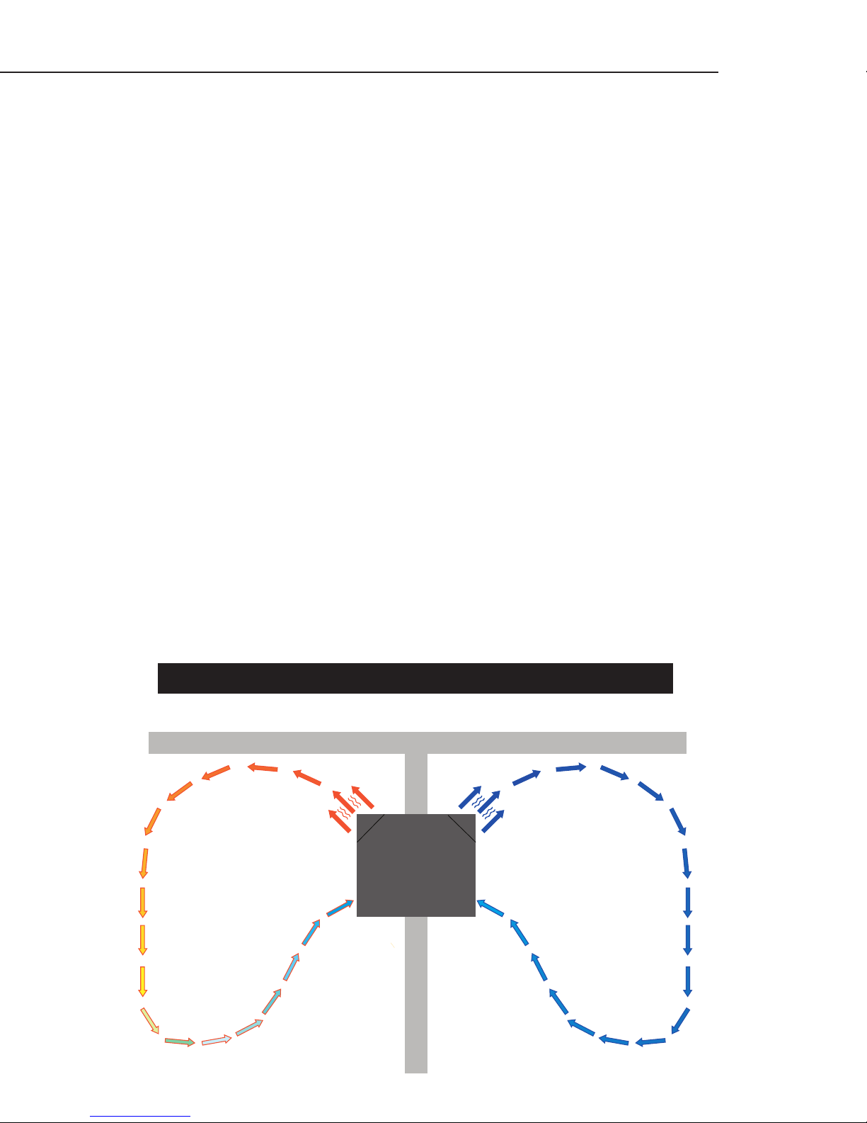
Carefully remove your CellarCool unit from the box. Place the CellarCool system on a tabletop to prepare it for installation and
testing. Plug system into a live electrical outlet and turn it on. The system may take up to 10 to 15 minutes before all four fans are
running, cold air is coming out on the cellar side, and hot air is coming out on the exhaust side. Once the operation has been tested,
turn the unit o and unplug it from the electrical outlet.*
*NOTE: If the system does not seem to be fully functional after 15 minutes, please refer to the Troubleshooting Guide on page 19.
Units weigh 55-101 pounds and are cumbersome for one person to carry. We recommend that you get someone else to help you
during the installation process. NEVER LAY UNIT ON ITS SIDE.
cx8800
Accessory kit #1:
•(1) CellarCool CX Series owner’s
manual
•(2) Mounting flanges
•(2) Magnetic deflectors for airflow
control
•(18) Anti-microbial pan tabs
•(1) Drain line brush
Accessory kit #2:
•(8) #6 x 1¾" hex washer head screws
• (6) ½" pan-head screws
•(1) ½" ID plastic tubing (10 feet)
•(2) Pieces of insulation foam (20")
•(2) Pieces of insulation foam (17")
cx2200
Accessory kit #1:
•(1) CellarCool CX Series owner’s
manual
•(2) Mounting flanges
•(2) Magnetic deflectors for airflow
control
•(18) Anti-microbial pan tabs
•(1) Drain line brush
Accessory kit #2:
•(8) #6 x 1¾" hex washer head screws
• (6) ½" pan-head screws
•(1) ½" ID plastic tubing (10 feet)
•(2) Pieces of insulation foam (20")
•(2) Pieces of insulation foam (17")

www.cellarcool.com | Page 5
CX SERIES
QUICK REFERENCE GUIDE
Front / Side View
Rear / Side View
Controller Power cord
(front location standard)
ON/OFF switch
(for 4400 & 8800 models only)
Power cord
(rear location optional)
Air sensor
Rear drain port
Access door

Page 6 | 1-855-235-5271 CX 040418
UNIT SPECIFICATIONS
cx2200 cx3300 cx4400 cx8800
Cellar Size (cu. ft.)* 300 650 1000 2000
Dimensions 14.25"W x 13.25"H x
16.38"D 14.25"W x 19.75"H x 21.63"D 16.25"W x 22"H x
22.25"D
Weight (lb.) 45 55 67 75
Amps (running) 3 5 7 10
dBA 60 60 60 65
Installation Through the wall
Thermostat Digital display
Temp. Delta 30°F temperature differential between wine cellar and ambient temperature
(maintains proper cellar temperature when exhaust environment does not exceed 85°F)
Warranty 2 years (parts and labor) / 5 years (compressor)
* Sizing the Unit to the Room
The specication chart will provide information on the unit's cooling capacity. There are circumstances in which a cellar design may
require a larger unit due to preexisting design restrictions. Certain building materials such as glass, stone, or concrete may seem
adequate but do not oer the insulation capacity required to maintain the optimum temperature for storing wine. We recommend
purchasing a unit with a larger capacity to compensate for these design limitations. Undersized cooling units can lead to premature
failure and/or prevent the system from reaching the desired set temperature. As a result, they are not covered under warranty.

www.cellarcool.com | Page 7
CX SERIES
CellarCool'sDynamiC airflow CirCulation
The performance and life of your system is contingent upon the steps you take in preparing the wine cellar. Improperly preparing
your enclosure or incorrectly installing your unit may cause unit failure, leaking of condensation, and other negative side eects.
It is highly recommended that you obtain the assistance of a wine storage professional.
Wine storage professionals work with licensed contractors, refrigeration technicians, and racking companies to build well-insulated,
beautiful, and protective wine cellars. CellarCool has put together some useful tips to assist in the installation process. Our
recommendations are meant to act as a guide in the process of building a proper enclosure. Your intended location may have
specic needs which we do not address.
Wall & Ceiling Framing
Build wine cellar walls using standard 2x4 or 2x6 boards and ceiling joists without violating local or state codes in your area. As a
general rule, the thicker the walls and the higher the insulation value, the more consistent your cellar temperature will be.
Insulation
Insulation is REQUIRED in order to properly use CellarCool products. It is vital that all walls and ceilings be insulated to keep the cellar
temperature as consistent as possible during the summer and winter months. Standard berglass or rigid foam insulation is normally
used in cellar construction; in some cases,“blown-in”insulation is used. The R-value, or quality of insulation, is determined by the
rate at which heat passes through the insulation. The higher the R-value, the more resistant the insulation is to conducting heat,
and the more consistent your wine cellar’s temperature will be. Using higher R-values in insulation will lower your operating costs
and CellarCool unit run time. (R-13 is the recommended minimum; R-19 is preferred for interior cellar walls, and R-30 for ceilings and
exterior walls.)
Mounting the Unit
The unit should be mounted within 18 inches of the ceiling in order to achieve sucient cooling. As the room cools down, the warm
air will rise to the ceiling. Mounting the unit high in the room will create a consistently cool environment by capturing the warm air
and replacing it with cool air. Mounting the unit low in the room will result in a temperature variation in the room due to the unit’s
inability to draw warm air from the ceiling down to the unit itself.
PREPARING THE WINE CELLAR
Cellar Wall
85ºF 55ºF
CellarCool
45°angled fans
(side view)
FRONT - WINE CELLARBACK - EXHAUST ROOM

Page 8 | 1-855-235-5271 CX 040418
Ventilation
The necessity of dissipating heat away from the unit is critical to the unit’s performance and cannot be overstated. As the unit
operates and cools, a greater amount of heat is generated on the exhaust side of the unit. Adequate ventilation is required in order to
dissipate heat away from the unit. If ventilation is inadequate, the exhaust will heat up and adversely aect the unit’s ability to cool.
Vapor Barrier
Water vapor creates its own pressure, separate from the ambient air pressure, and will intrude into colder/drier areas. A vapor
barrier is REQUIRED in order to prevent the intrusion of water vapor and maintain the correct cellar temperature and humidity. It
is recommended that 6-millimeter plastic sheeting be applied to the warm side of the cellar walls. The vapor barrier must also be
applied to the outside walls and ceiling. If it is impossible to reach the outside, then the plastic must be applied from within the
cellar. The most common method is to wrap the entire interior, leaving the plastic loose in the stud cavity so the insulation can be
placed between each stud. All of the walls and ceiling must be wrapped in plastic for a complete vapor barrier.
In areas of high humidity, such as Southern and Gulf States, the vapor barrier will prevent inltration of warm moist air. The moist
air can cause mold to form, and standing water in drip trays promote microbial and fungal growth that cause unpleasant odors and
indoor air quality problems. If mold is found, remove it immediately and sanitize that portion of the unit.
NOTE: High humidity signicantly increases the heat load on the cooling system.
Any break in the vapor barriers (a cut, a nail hole, overlapping, etc.) will cause a moisture leak and must be sealed. The electric conduit
is a “duct” for vapor to travel in. The conduit should be caulked and sealed on the warm air end.
Unobstructed Airow
Unobstructed airow to and from the unit is a critical factor in the unit’s overall performance. Make sure there is a minimum of three
feet of clearance in every direction around the unit (ve feet is ideal).This will assure that the unit can move the air around in an ecient
manner. Do not attempt to mount the unit in a wall recess or attempt to camouflage or cover the unit with any sort of aftermarket
grille, accessory, etc. This can restrict airflow, prevent the unit from working properly, and void the warranty. Please feel free to call Cel-
larCool Customer Service with any questions or concerns regarding installation requirements.
Ambient Temperature Factor
The cooling system has the ability to cool a maximum of 30°F below the ambient temperature of the room to which it is exhausting.
Therefore, you want to exhaust the unit in a room which will not exceed 85°F and preferably remains at a consistent 75°F. Otherwise
the unit will not have the capacity to keep the wine at a desirable 55°F.
Door and Door Seal
An exterior-grade (1¾”) door must be installed as a cellar door. It is very important that weather stripping is attached to all four sides
of the doorjamb. A bottom “sweep” or threshold is also required. The door must have an excellent seal to keep the cool cellar air from
escaping the cellar. If the door is not sealed properly, the cooling system may run continuously, shortening its operational lifespan.

www.cellarcool.com | Page 9
CX SERIES
AIRFLOW CONTROL
Airow Options
The magnetic deectors can be used in a variety of ways, such as mounting the system lower in the cellar, ush-mounting the
condenser side of system, and directing airow to avoid recirculation. Simply apply the magnetic deectors in one of the positions
displayed below. Choose the option that will best suit your installation.
NOTE: Do not cover both of the openings on the same side of the unit for
any reason. This will cause cooling issues and premature failure.
NOTE: Do not cover both of the openings on the same side of the unit for
any reason. This will cause cooling issues and premature failure.
ONE-SIDE SELECTIVE AIRFLOW OPTIONS
TWO-SIDE SELECTIVE AIRFLOW OPTIONS
OPTION 1
OPTION 5
OPTION 2
OPTION 6
OPTION 3
OPTION 7
OPTION 4
OPTION 8
NOTE: If installing the magnetic deectors on the face of the cx4400 unit, excess material may need to be trimmed.

Page 10 | 1-855-235-5271 CX 040418
Locate the desired installation location (no lower than 18 inches from the ceiling). Using
a stud nder, locate the studs on either side of the center point, and mark them with
vertical lines.* Using a level and a pencil, mark a horizontal line on the wall between the
two studs, no less than 1½ inches and no more than 18 inches from the ceiling.
* For the cx8800, special consideration needs to be used when selecting the installation
location. The system is wider than the 16 inches at which wall studs are typically spaced,
and will require the removal of at least one stud.
Using a ruler or measuring tape, measure vertically down 13.5 inches for the cx2200, 20
inches down for the cx3300/cx4400, and 22.5 inches for the cx8800. Mark another hori-
zontal line parallel to the rst one.
Using a saw, cut along the uppermost horizontal line until your saw reaches the stud.
Turn the saw around, inserting it into the cut you have just made, and cut toward the
opposite stud so that you have a clean horizontal cut between the two studs. Be careful
not to cut into the studs themselves.*
* For the cx8800, cut out your drywall rst and cut through your studs when you have a clear
understanding what is inside the wall.
Now make the second horizontal cut from stud to stud on the line below the rst cut.
Once the horizontal lines have been cut, make vertical cuts using the inside edge of the
studs as a guide. Once you have made both vertical cuts, you should have a rectangular
hole in the sheetrock. Now make the same hole on the other side of the wall. Since you
already have one hole, this is an easy process. Using a nail, mark all four corners of the
rst hole by making nail holes through the sheetrock. Then, on the other side of the wall,
connect the holes with a pencil mark and cut.
Sheetrock alone cannot support the weight of a cooling system. Therefore, it is
necessary to frame the hole that you have just cut with upper and lower supports. These
supports also provide solid material for the mounting bracket screws.
Using two 2x4s at 14.5 inches in length and eight 6d nails, secure the upper and lower
supports to the right and left studs, just inside the sheetrock. Make sure that the internal
height remains the same so that the system will t snugly through the framed cut-out.*
* For the cx8800, it is recommended that the entire opening be framed. This system is heavy
and the sturdier the frame, the better.
PREPARING THE INSTALLATION LOCATION
Minimum Tools Needed:
Hammer SawScrewdriver
Level

www.cellarcool.com | Page 11
CX SERIES
PREPARING THE UNIT FOR INSTALLATION
Two-Piece Mounting Flanges
The unit utilizes two (2) mounting anges that attach to each side
of the unit on the exterior side of the installation location.
INSTALLING THE UNIT
Installing the Unit
1. Slide the unit into the installation location from inside the cellar. Make sure the controller
side of the unit is inside of the cellar.
Note: If you use decorative moulding, it should be
attached to the walls and never to the cooling unit itself.
The moulding itself should be removable incase the unit
needs servicing.
Applying Insulation Tape
Locate the two (2) 17-inch pieces and two (2) 20-inch pieces of
insulation foam tape provided with the unit. Peel back the white-
paper adhesive covering and place on the mounting anges
as shown. The 20-inch pieces will go between the unit and the
bracket, and the 17-inch pieces will go between the bracket and
the wall. This foam creates a tight seal around the unit.
Front of Unit
Cellar Wall

Page 12 | 1-855-235-5271 CX 040418
Mounting Bracket Installation
Select your desired bracket mounting location (see diagram below). This location determines the depth of the installation. For
example, position #1 keeps most of the unit out of the cellar, while position #2 makes the back of the unit almost ush with the
exterior wall. Place the anges onto unit. Pay special attention to the direction the foam side is facing: it needs to be towards the
wall. Use the (6) ½" hex-head self-tapping screws to fasten the bracket to the unit. Do NOT use screws longer than ½" in length.
Installing the Mounting Flange (from outside the cellar)
1. On each side of the side of the unit you will notice 6 indents; these mark two dierent
installation depths. Select one of the two mounting depths and attach each mounting
bracket to the unit with the supplied self-tapping screws.
2. Finally, secure the mounting brackets to the wall through the pre-drilled
holes with the supplied #6 1¾" hex-head screws. The screws should
penetrate the studs to provide adequate support for the unit (see
illustration).
3. Use the two (2) remaining pieces of supplied foam tape to seal the
gaps at the top and bottom of the unit.
4. Seal any remaining cracks and gaps around the unit from inside the
cellar with an airtight sealant or caulking to prevent air leakage.
5” inch thick wall
(wall thickness may vary) Mounting bracket
Wine Cellar Exhaust Area
#2#1
Mounting Flange
Back of Unit
Exterior of Cellar Wall

www.cellarcool.com | Page 13
CX SERIES
DRAIN LINE
Drain Line Connection
It is important that the drain line tube be properly connected and used to prevent leakage and other problems associated with
excess condensation. If the drain line is draining into a vessel, make sure that the drain line hangs above the surface and is not
submerged. This will prevent the formation of mold.
*INCORRECT: Do not allow the
drain line to be submerged (if
draining into a vessel).
*CORRECT: Drain line should
hang above the waterline.
Condensation Drain Line Tube
The condensation drain line tube is used to remove excess condensation from the unit to a proper discharge location. It is
important that the drain line tube be properly connected and used to prevent leakage and other problems associated with
excess condensation.
Failure to use the condensation drain line tube will void the warranty on the unit.
To attach the drain line tube:
1. Wrap tee with Teon tape one or two
turns clockwise.
2. Next, thread the barb tee into the rear
drain port and rotate until tight. Make sure
the tees of the barb are sticking straight
up and down.
3. Next, attach the piece of rubber ½" ID
hosing to the lower tee of the barb.
4. Every six weeks, disconnect the drain
line from the barb tee. Remove the barb
from the rear drain port and clean it. Then
use the supplied drain line brush to clean
the interior drain line. Use the drain line
access door (pictured at right) to drop a
pan tab into the drip tray to prevent the
buildup of microbial growth.
Access door

Page 14 | 1-855-235-5271 CX 040418
SYSTEM OPERATION
Initial Start-Up
When power is applied to the unit, the control will briey
display all symbols, and the snowake symbol will be displayed
(if unit is calling for cooling). There may be a brief delay (up to
60 seconds) prior to the evaporator fan turning on. When the
evaporator fan is activated, the fan symbol will display.
APST (Advance Product Safety Technology) is a temperature
control feature for the evaporator fan that comes standard with
all CellarCool units. APST ensures that in the possible event of
a cooling deciency, the heat from the indoor fan will not raise
the temperature of the wine cellar, which could otherwise have
an adverse eect on the wine-aging process.
Setpoint
The setpoint is preset at the factory (CellarCool) to 55F°. It can
be adjusted by the customer between 50°F and 70°F (in 1°F
increments).
Cooling Operation
Cooling is activated once the air sensing probe senses a
temperature that is 4°F greater than the setpoint. The controller
then energizes the compressor relay which activates the
compressor. The evaporator and condenser fans operate with
the compressor. The unit provides cooling until the air-sensing
probe senses the setpoint has been reached. At this point the
compressor relay is de-energized, which stops the compressor.
Anti-Short Cycle
The Anti-Short Cycle ensures that the compressor will remain
o for a period of three minutes after the unit has reached
the setpoint to allow the pressure in the refrigeration unit to
equalize prior to starting the compressor.
Anti-Frost Cycle (defrost)
After two hours of compressor operation, the controller will
activate the Anti-Frost cycle. The compressor relay will de-
energize, stopping the compressor, evaporator fans, and
condenser fans. The compressor relay will remain de-energized
for ve minutes, and then the unit will return to normal
operation. The setpoint and the dripping snowake symbol will
be displayed during the Anti-Frost cycle.
Air-Sensing Probe Failure Protection
In the event that an air-sensing probe should fail, the APST
(Advance Product Safety Technology) will automatically
transition the compressor to a timed cycle based on detailed
laboratory testing, which will ensure that the product is kept
within a safe temperature range.
Display
The setpoint is displayed by default. “Def” is displayed during
Anti-Frost. The air sensing probe and evaporator probe
temperatures can be accessed by pushing the SET button and
scrolling through“PB1” (air sensing probe).
Safety Features
Once the compressor relay is de-energized the controller must
wait ve minutes before reenergizing the relay. This prevents
the compressor from repeatedly turning o and on. If the unit
is calling for cooling during this time, the compressor symbol
will blink, indicating that cooling is needed but the control is
waiting for the Anti-Short cycle delay.
In the event of a faulty air-sensing probe, the compressor will
cycle o for 10 minutes and on for 40 minutes. “E1” will be
displayed on the screen.
Alarms
See “Alarm Codes”in Controller Function chart.

www.cellarcool.com | Page 15
CX SERIES
CONTROLLER FUNCTIONS
Button/Symbol Normal Functions
ON/OFF • Press and hold the ON/OFF button for approximately three (3) seconds to turn the unit on or o.
NOTE: This does not disconnect power from the unit. In order for the power to be shut o from the unit,
the power cord must be unplugged from the wall receptacle.
• This button also serves as an escape button.
UP/DOWN ARROWS • Use these buttons to scroll up or down a menu.
• Press and hold the UP ARROW button for approximately ve seconds to manually start the Anti-
Frost Cycle.
SET • Press the SET button once to view the setpoint or the temperature of the air-sensing probe.
• Once the SET button is pressed“SEt” will be displayed. Press the UP or DOWN ARROW buttons to
scroll through Pb1 and the setpoint parameter.
• Press the SET button again to view any of these values.
• To change the setpoint, press the SET button. When“SEt” is displayed on the screen, press the SET
button once more. Use the UP and DOWN ARROW buttons in order to change the value until the
desired setpoint is reached.
• Hold the set button for approximately 5 seconds to enter the CPSM (Customer Preference
Selection Mode) menu. CPSM details are available on the next page.
SNOWFLAKE Constant: The unit is in cooling mode and the compressor and fans are running.
Blinking: The unit is calling for cooling, but must wait 5 minutes before restarting the compressor.
This ve-minute delay serves as an anti-short cycle for the compressors protection.
DRIPPING SNOWFLAKE The unit is in defrost mode. The compressor and fans will be turned o during this cycle.
Compressor On
Unit is in Defrost Mode
Alarm is Present
Temperature Measurement
Menu Navigation
& Value Increase
(Press and hold to
manually enter defrost
mode.)
Power On/O
(hold for approx. 3 seconds)
& Escape
Menu Navigation
& Value Decrease
Probe Value &
Alarm Folder
(Press and hold to enter the
parameter menu.)
ALARM The alarm symbol is shown when the unit encounters an issue that needs attention. The displayed
alarm codes are explained on the next page. The alarm code will remain displayed until corrected.

Page 16 | 1-855-235-5271 CX 040418
ALARM CODES
CPSM (CUSTOMER PREFERENCE SELECTION MODE)
Message Cause Solution
“E1” Faulty air-sensing probe Contact Customer Service at 1-800-343-9463.
“AH1”
The air probe is sensing
a temperature that is 10°
above the setpoint
1. Allow time for the wine to reach the desired temperature.
2. Make sure all windows and doors are closed and have a proper seal.
3. Follow the procedures in the pre-installation instructions to test the unit for proper
cooling.
“AL1”
The air probe is sensing
a temperature that is 10°
below the setpoint
1. Make sure unit is not in cooling mode. (The snowake symbol will not be lit.)
2. Add heat to the room until the wine reaches the desired temperature.
Press and hold the SET button for approximately 5 seconds to enter the CPSM menu.
Use the DOWN ARROW button to access the following parameters.
PA2 No adjustable settings in this parameter.
tab No adjustable settings in this parameter.
Rel No adjustable settings in this parameter.
LOC Change this parameter from“n” to “y” to lock the keyboard from changes to the setpoint.
CA1 Increase or decrease the temperature reading of the air sensor. (This process recalibrates to
the sensor.) Increasing the value by 1 means an increase in the temperature reading by 1
degree. This parameter can be adjusted +- 12 degrees. If needed: Adjust this setting to match
your temperature sensor located inside of the cellar.

www.cellarcool.com | Page 17
CX SERIES
cx2200 & cx3300 CONTROLLER WIRING SCHEMATIC
Cond.
Fan
Compressor
Cond.
Fan
Evap
Fan
Evap
Fan

Page 18 | 1-855-235-5271 CX 040418
cx4400 CONTROLLER WIRING SCHEMATIC
Cond.
Fan
Compressor
Cond.
Fan
Evap
Fan
Evap
Fan
This manual suits for next models
3
Table of contents
Other Cellar Cool Cooling Box manuals