Nibe ACS 310 User guide

LEK
LEK
LEK
ACS 310
SE
Installatörshandbok dockningssats kyla (4-rör)
GB
Installer manual docking kit cooling (4-pipe)
DE
Installateurhandbuch Ansclusssatz Kühlung (Vierrohr)
FI
Asentajan käsikirja liitäntäsarja Jäähdytys (4-putki)
DK
Installatørhåndbog Sammenkoblingssæt køling
(4-rør)
IHB 1732-2
331426


Svenska
Allmänt
ACS 310 är ett tillbehör som möjliggör för
VVM 225/VVM 310/VVM 320/VVM 325 att styra produk-
tion av kyla.
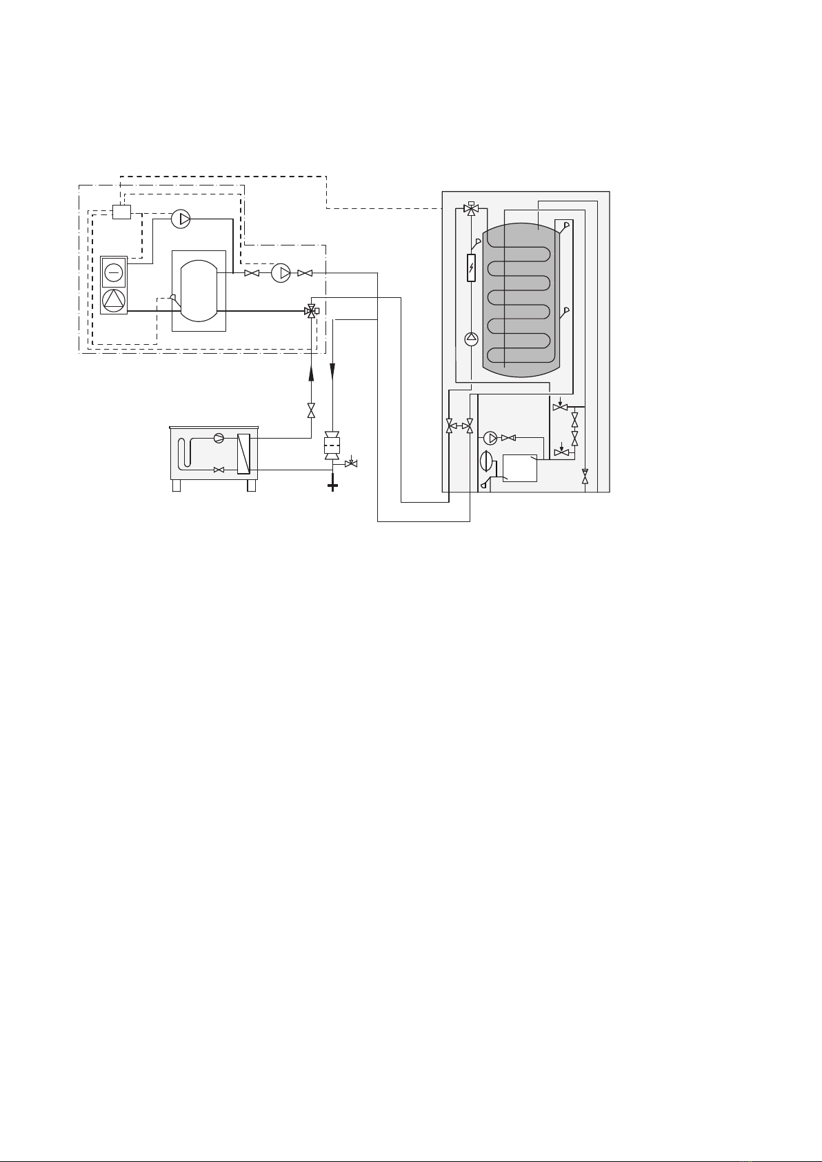
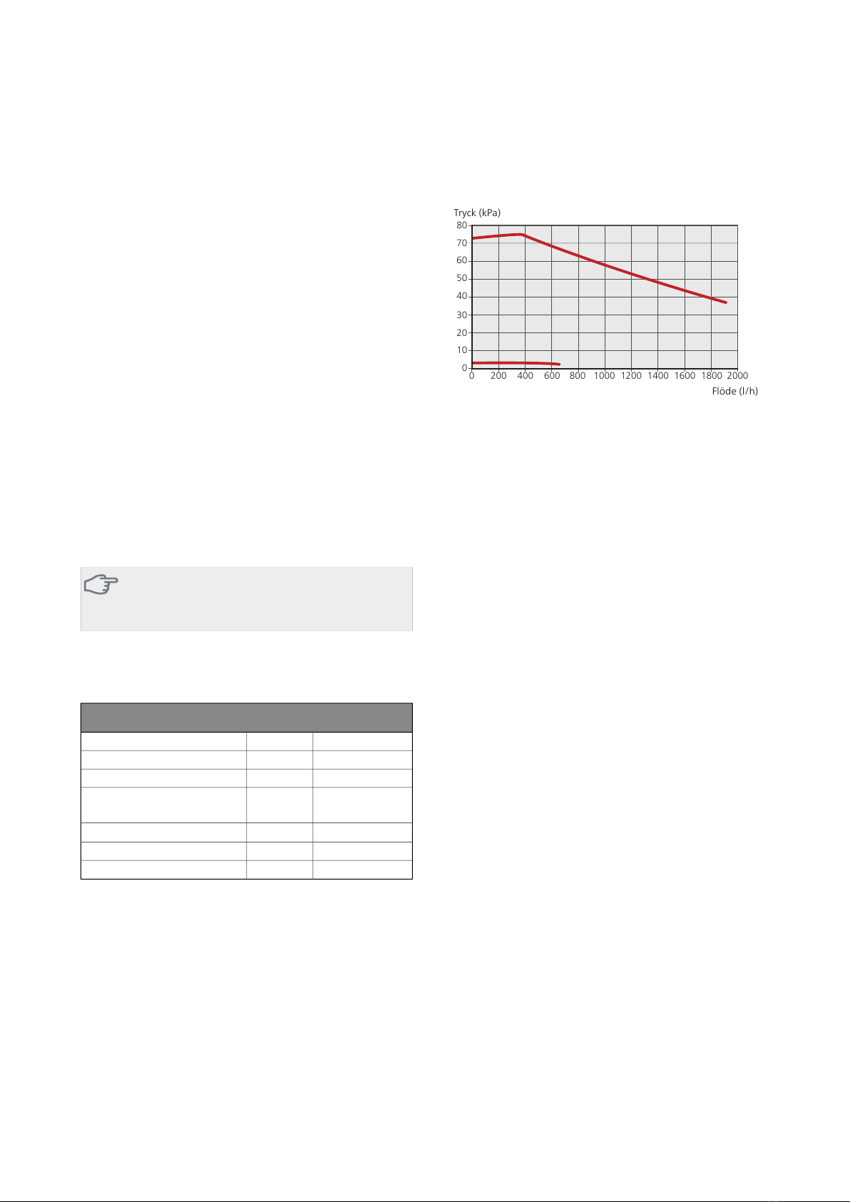
Kylsystemet tillförs kyla från värmepumpen med hjälp
av en cirkulationspump via en växelventil.
För att anläggningen ska fungera krävs fritt flöde över
kylsystemet tex. med hjälp av volymkärl för kyla.
Driftläge kyla aktiveras av temperaturen på utgivaren
och eventuell rumsgivare, rumsenhet eller separat
rumsgivare för kyla (om exempelvis två olika rum ska
kylas respektive värmas samtidigt).
Vid kylbehov aktiveras växelventilen kyla och kylcirkula-
tionspumpen. Produktion av kyla reglerar efter kylgivaren
och ett kylbörvärde som bestäms av vald kylkurva.
Gradminuter beräknas efter värdet på den externa
temperaturgivaren för kyla ut och kylbörvärdet.
Kompatibla produkter
TÄNK PÅ!
För att tillbehöret ska fungera krävs att en NIBE
luft/vattenvärmepump är ansluten till systemet.
■VVM 225
■VVM 310
■VVM 320
■VVM 325
Innehåll
Cirkulationspump1 st
PWM-kabel till cirkulationspump1 st
Kraftkabel till cirkulationspump1 st
Kulventiler med unionsmutter2 st
Planpackningar2 st
Buntband2 st
Ställdon växelventil1 st
Adapter kit, ställdon1 st
Växelventil1 st
Apparatlåda1 st
Värmeledningspasta1 st
Aluminiumtejp1 st
Isoleringstejp1 st
Temperaturgivare1 st
Inomhusgivare1 st
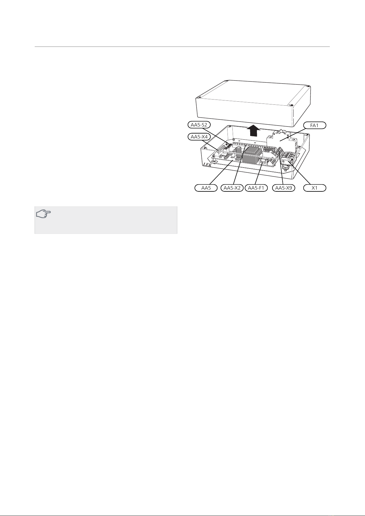
Komponentplacering apparatlåda (AA25)
LEK
AA5-X4
AA5-S2
AA5-X2 AA5-X9 X1
FA1
AA5-F1AA5
Elkomponenter
Automatsäkring, 10AFA1
Anslutningsplint, spänningsmatningX1
TillbehörskortAA5
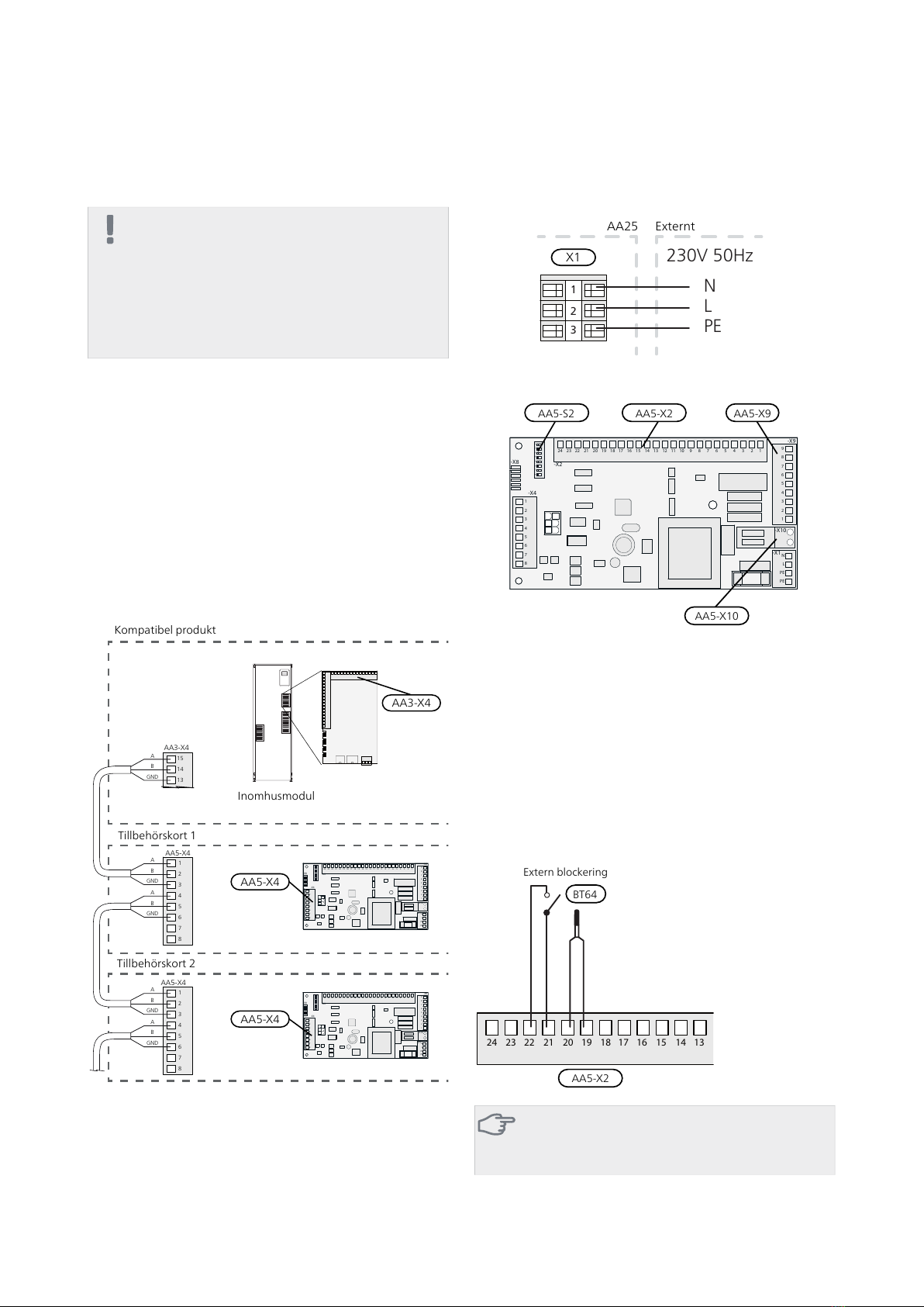
Anslutningsplint, givare och extern blocke-
ring
AA5-X2
Anslutningsplint, kommunikationAA5-X4
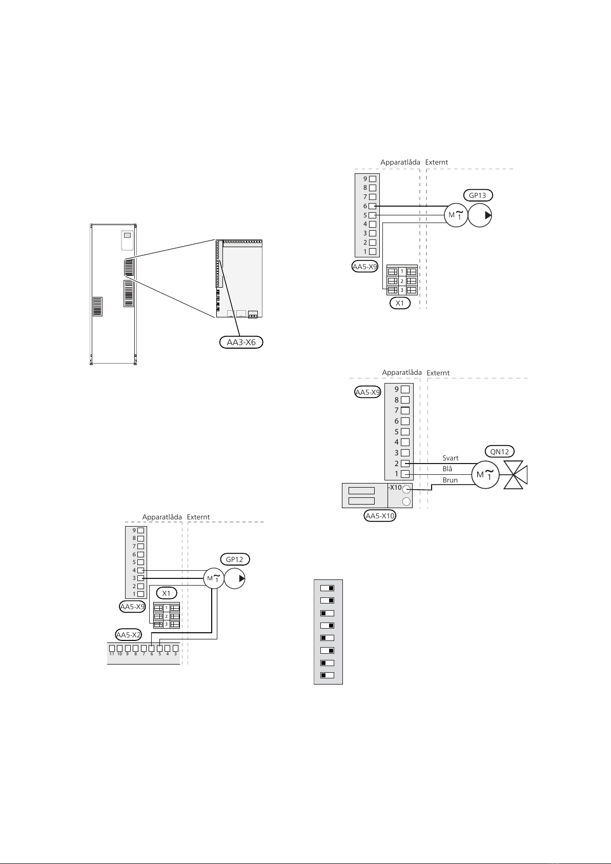
Anslutningsplint, cirkulationspump, shunt
och hjälprelä
AA5-X9
DIP-switchAA5-S2
Finsäkring, T4AH250VAA5-F1
Beteckningar i komponentplacering enligt standard IEC
81346.
3ACS 310 | SE

Röranslutning
Allmänt
För att undvika kondensbildning måste rörledningar och
övriga kalla ytor isoleras med diffusionstätt material. Vid
stort kylbehov krävs fläktkonvektor med droppskål och
avloppsanslutning.
Röranslutningar
1. Om inomhusmodulen redan är installerad och vat-
tenfylld så ska klimatsystemet och inomhusmodulen
tömmas på vatten. Se installatörshandboken för in-
omhusmodulen för ytterligare instruktioner.
2. Rör till och från kylackumulatorn kopplas in mellan
värmepumpen och inomhusmodulen.
TIPS!
För att undvika onödiga värmeförluster bör rö-
ren isoleras.
Cirkulationspump
Montera kulventilerna på cirkulationspumpen. Använd
medföljande planpackningar som tätning.
LEK
Kulventil
Planpackning
Cirkulationspump
Växelventil
Montera växelventilen (QN12) med port AB som inkom-
mande framledning från värmepumpen, port A mot ky-
lackumulatorn och port B mot värmesystemet. Montera
den så att port AB är öppen mot port B när motorn är i
viloläge. Vid signal öppnar port AB mot port A.
LEK
LEK
A
B
AB
Temperaturgivare
Temperaturgivaren för ACS 310(BT64) placeras på
framledningen från kylackumulatorn
LEK
LEK
E
Temperaturgivaren monteras med buntband tillsammans
med värmeledningspasta och aluminiumtejp. Därefter
ska den isoleras med medföljande isolertejp.
OBS!
Givar- och kommunikationskablar får ej förläg-
gas i närheten av starkströmsledning.
ACS 310 | SE4

Systemprincip
Förklaring
KylsystemEQ1
Apparatlåda med tillbehörskort, kylaAA25
Temperaturgivare, kylaBT64
AckumulatortankCP10
Laddpump, kylaGP12
Cirkulationspump, kylaGP13
Växelventil, kylaQN12
VVM 225/VVM 310/VVM 320/VVM 325EB15
F2040/F2120EB101
SäkerhetsventilFL10
AvtappningsventilQM1
AvstängningsventilQM40 -QM42
TrimventilRN10
Anslutning värmebärare, framXL1
Anslutning värmebärare, returXL2
Filterkulventil, smutsfilterQZ2
Övrigt
Säkerhetsventil, klimatsystemFL2
ExpansionskärlCM1
Beteckningar enligt standard IEC 61346-2.
Dockning till kyla
Kyldrift prioriteras enligt valda inställningar i inomhusmodulen.
Principschema
OBS!
Nedanstående bilder är principscheman. Verklig anläggning ska projekteras enligt gällande normer.
Principschema VVM 225 med ACS 310
-EB15
P
-BT3
-BT7
-BT63
-BT2
-BT6
-EB101
-XL1
-XL2
-XL9
-XL8
-FL10
-QM1
-QZ2
-QM40
-QM41-QM42
-CP10
-BT64
-QN12
-AA25
-EQ1
-GP13
-GP12
5ACS 310 | SE

Principschema VVM 310 med ACS 310
-EB15-FL2
-EB15
-CM1
-EB15
-EB101
-XL2
-XL1
-QM1
-FL10
-QM40
-QZ2
-CP10
-BT64 -QN12
-AA25
-EQ1
-GP13
-GP12
-QM41
-QM42
Principschema VVM 320 med ACS 310
-CP10
-QN12
-AA25
-EQ1
-GP13
-GP12
-BT64 -QM41-QM42
-EB101
-XL2
-XL1
-QM1
-FL10
-QM40
-QZ2
-EB15
ACS 310 | SE6

Principschema VVM 325 med ACS 310
-EB15
-XL9
-XL8
-EB101
-XL2
-XL1
-QM1
-FL10
-QM40
-QZ2
-CP10
-BT64 -QN12
-AA25
-EQ1
-GP13
-GP12
-QM41-QM42
7ACS 310 | SE

Elinkoppling
OBS!
All elektrisk inkoppling skall ske av behörig
elektriker.
Elektrisk installation och ledningsdragning skall
utföras enligt gällande bestämmelser.
Inomhusmodulen ska vara spänningslös vid in-
stallation av ACS 310.
Elschema finns i slutet av denna installatörshandbok.
Anslutning av kommunikation
VVM225/VVM 310/VVM 320/VVM 325
Detta tillbehör innehåller ett tillbehörskort (AA5) som
ska anslutas direkt till inomhusmodulen på ingångskortet
(plint AA3-X4).
Om flera tillbehör ska anslutas eller redan finns installe-
rade måste nedanstående instruktion följas.
Det första tillbehörskortet ska anslutas direkt till inom-
husmodulens plint AA3-X4. De efterföljande korten an-
sluts i serie med föregående kort.
Använd kabeltyp LiYY, EKKX eller likvärdig.
1
2
3
4
5
6
7
8
AA5-X4
15
A
B
GND
A
B
GND
A
B
GND
A
B
GND
A
B
GND
14
13
AA3-X4
1
2
3
4
5
6
7
8
AA5-X4
1
2
3
4
5
6
7
8
15
14
13
1
2
3
4
5
6
7
8
Kompatibel produkt
Tillbehörskort 1
Tillbehörskort 2
ON
12345678
-X9
-X2
24 20212223 1516171819 1011121314 56789 1
1
N
L
PE
PE
1
2
3
4
5
6
7
8
2
3
4
5
6
7
8
9
234
-X8
-X4
-X10
-X1
AA5-X4
ON
12345678
-X9
-X2
24 20212223 1516171819 1011121314 56789 1
1
N
L
PE
PE
1
2
3
4
5
6
7
8
2
3
4
5
6
7
8
9
234
-X8
-X4
-X10
-X1
AA5-X4
Inomhusmodul
AA3-X4
Anslutning av matning
Anslut spänningsmatningen till plint X1 enligt bild.
3
2
1N
230V 50Hz
L
PE
AA25 Externt
X1
Översikt tillberhörskort (AA5)
ON
12345678
-X9
-X2
24 20212223 1516171819 1011121314 56789 1
1
N
L
PE
PE
1
2
3
4
5
6
7
8
2
3
4
5
6
7
8
9
234
-X8
-X4
-X10
-X1
AA5-X2 AA5-X9
AA5-X10
AA5-S2
Anslutning av givare och extern blockering
Använd kabeltyp LiYY, EKKX eller likvärdig.
Temperaturgivare (BT64)
Anslut givaren till AA5-X2:19-20.
Extern blockering (valfritt)
En kontakt kan anslutas till AA5-X2:21-22 för att kunna
blockera kyldriften. När kontakten sluts blockeras kyldrif-
ten.
24 20212223 1516171819 1314
Extern blockering
AA5-X2
BT64
TÄNK PÅ!
Reläutgångarna på tillbehörskortet får max be-
lastas med 2 A (230 V) totalt.
ACS 310 | SE8

Temperaturgivare (rumsgivare för kyla, BT74)
En extra temperaturgivare (rumsgivare för kyla) kopplas
till inomhusmodulen för att bättre kunna avgöra när det
är dags att byta mellan kyl- och värmedrift.
Temperaturgivaren kopplas in på någon av AUX-ingång-
arna X6:7-19 på plint X6 som är placerad bakom front-
luckan i inomhusmodulen. Den aktuella AUX-ingången
väljs i meny 5.4. Jord ansluts till plint X6:GND. Använd
en 2-ledare med minst 0,5 m² kabelarea.
AA3-X6
Temperaturgivaren placeras på en neutral plats i rummet
där inställd temperatur önskas. Det är viktigt att givaren
inte hindras från att mäta korrekt rumstemperatur, ex-
empelvis genom placering i nisch, mellan hyllor, bakom
gardin, ovanför eller nära värmekälla, i drag från ytterdörr
eller i direkt solinstrålning. Även stängda radiatortermo-
stater kan orsaka problem.
Anslutning av laddpump (GP12)
Anslut laddpumpen (GP12) till AA5-X9:4 (230 V), AA5-
X9:3 (N) och X1:3 (PE) samt AA5-X2:5 och AA5-X2:6
(signal).
1
2
3
4
5
6
7
8
9
3
2
1
3
4567891011
Apparatlåda Externt
AA5-X9
X1
GP12
AA5-X2
Anslutning av cirkulationspump (GP13)
Anslut cirkulationspumpen (GP13) till AA5-X9:6 (230 V),
AA5-X9:5 (N) och X1:3 (PE).
1
2
3
4
5
6
7
8
9
3
2
1
Apparatlåda Externt
AA5-X9
X1
GP13
Anslutning av växelventilsmotor (QN12)
Anslut motorn (QN12) till AA5-X9:2 (signal), AA5-X9:1
(N) och AA5-X10:2 (230 V).
-X10
1
2
3
4
5
6
7
8
9
Apparatlåda Externt
AA5-X9
AA5-X10
QN12
Svart
Blå
Brun
DIP-switch
DIP-switchen (S2) på tillbehörskortet (AA5) ska ställas in
enligt nedan.
ON
12345678
9ACS 310 | SE

Programinställningar
Programinställningen av ACS 310 kan göras via startgui-
den eller direkt i menysystemet.
Startguiden
Startguiden visas vid första uppstart efter värmepumps-
installationen, men finns även i meny 5.7.
Menysystemet
Om du inte gör alla inställningar via startguiden eller
behöver ändra någon inställning kan du göra detta i
menysystemet.
Meny 1.9.5 - Kylinställningar
Meny 4.2 - "Driftläge"
Välj mellan olika driftlägen.
Meny 4.9.2 - Autolägesinställningar
Här ställer du in de temperaturer, som styr när värme
resp. kyla får vara aktiv i driftläge AUTO
Meny 5.2 - systeminställningar
Aktivering/avaktivering av tillbehör.
TÄNK PÅ!
Se även Installatörshandboken för inomhusmo-
dulen.
Tekniska uppgifter
Tekniska data
ACS 310
230V ~ 50 HzSpänning cirkulationspump
230V ~ 50 HzSpänning växelventil
G1Anslutning pump
G1 x Ø 22 mm
klämring
Anslutning kulventil
7,5kvs-värde växelventil
067 248Art nr
624 69 16RSK nr
Pumpkapacitetsdiagram
Tillgängligt tryck cirkulationspump, GP1
Tryck (kPa)
Flöde (l/h)
00 200 400 600 800 1000 1200 1400 1600 2000
20
30
40
50
60
70
80
Tryck
(kPa)
Flöde
(l/h)
10
1800
ACS 310 | SE10

English
General
ACS 310 is an accessory that makes it possible for
VVM 225/VVM 310/VVM 320/VVM 325 to control pro-
duction of cooling.
The cooling system supplies cooling from the heat pump
using a circulation pump via a reversing valve.
For the installation to work the cooling system must flow
freely, for example using a volume vessel for cooling.
Operating mode cooling is activated by the temperature
of the outdoor sensor and any room temperature
sensors, room units or separate room sensors for cooling
(if two different rooms are to be heated respectively
cooled at the same time for example.)
When cooling is required the cooling reversing valve and
the circulation pump are activated. Cooling production
regulates according to the cooling sensor and a cooling
set point value that is determined by the selected cooling
curve. Degree minutes are calculated in response to the
value on the external temperature sensor for cooling
out and the cooling set point value.
Compatible products
Caution
In order for the accessory to work, a NIBE
air/water heat pump must be connected to the
system.
■VVM 225
■VVM 310
■VVM 320
■VVM 325
Contents
Circulation pump1 x
PWM cable for circulation pump1 x
Power cable to circulation pump1 x
Ball valves with union nut2 x
Flat gaskets2 x
Cable ties2 x
Actuator reversing valve1 x
Adapter kit, actuator1 x
Shuttle valve1 x
Unit box1 x
Heating pipe paste1 x
Aluminium tape1 x
Insulation tape1 x
Temperature sensor1 x
Indoor sensor1 x
Component location unit box (AA25)
LEK
AA5-X4
AA5-S2
AA5-X2 AA5-X9 X1
FA1
AA5-F1AA5
Electrical components
Miniature circuit breaker, 10 AFA1
Terminal block, power supplyX1
Accessory cardAA5
Terminal block, sensors and external block-
ing
AA5-X2
Terminal block, communicationAA5-X4
Terminal block, circulation pump, mixing
valve and auxiliary relay
AA5-X9
DIP switchAA5-S2
Fine wire fuse, T4AH250VAA5-F1
Designations in component locations according to
standard IEC 81346.
11ACS 310 | GB

Pipe connections
General
Pipes and other cold surfaces must be insulated with
diffusion-proof material to prevent condensation. Where
the cooling demand is high, fan convectors with drip
trays and drain connection are needed.
Pipe connections
1. If the indoor module has already been installed and
filled with water, the climate system and indoor
module must be drained of water. See the Installer
manual for the indoor module for further instruc-
tions.
2. Pipes to and from the cooling accumulator tank are
connected between the heat pump and the indoor
module.
TIP
To prevent unnecessary heat losses insulate the
pipes.
Circulation pump
Install the ball valves on the circulation pump. Use the
flat gaskets supplied to seal.
LEK
Ball valve
Flat gasket
Circulation pump
Shuttle valve
Install the reversing valve (QN12) with port AB as incom-
ing supply line from the heat pump, port A towards the
cooling accumulator and port B towards the heating
system. Install it so that port AB is open towards port B
when the motor is in standby. In the event of a signal,
port AB opens towards port A.
LEK
LEK
A
B
AB
Temperature sensor
The temperature sensor for ACS 310(BT64) is located on
the supply line from the cooling accumulator
LEK
LEK
E
Install the temperature sensor with cable ties with the
heat conducting paste and aluminium tape. Then insu-
late with supplied insulation tape.
NOTE
Sensor and communication cables must not be
placed near power cables.
ACS 310 | GB12

System diagram
Explanation
Cooling systemEQ1
Unit box with accessory board, coolingAA25
Temperature sensor, coolingBT64
Accumulator tankCP10
Charge pump, coolingGP12
Circulation pump, coolingGP13
Reversing valve, coolingQN12
VVM 225/VVM 310/VVM 320/VVM 325EB15
F2040/F2120EB101
Safety valveFL10
Tapping valveQM1
Shut-off valveQM40 -QM42
Trim valveRN10
Connection heating medium, supplyXL1
Connection heating medium, returnXL2
Filterball, particle filterQZ2
Miscellaneous
Safety valve, climate systemFL2
Expansion vesselCM1
Designations according to standard IEC 61346-2.
Docking to cooling
Cooling operation is prioritised according to selected settings in the indoor module.
Outline diagram
NOTE
The following images are the outline diagram. Actual installations must be planned according to applicable
standards.
Outline diagram VVM 225 with ACS 310
-EB15
P
-BT3
-BT7
-BT63
-BT2
-BT6
-EB101
-XL1
-XL2
-XL9
-XL8
-FL10
-QM1
-QZ2
-QM40
-QM41-QM42
-CP10
-BT64
-QN12
-AA25
-EQ1
-GP13
-GP12
13ACS 310 | GB

Outline diagram VVM 310 with ACS 310
-EB15-FL2
-EB15
-CM1
-EB15
-EB101
-XL2
-XL1
-QM1
-FL10
-QM40
-QZ2
-CP10
-BT64 -QN12
-AA25
-EQ1
-GP13
-GP12
-QM41
-QM42
Outline diagram VVM 320 with ACS 310
-CP10
-QN12
-AA25
-EQ1
-GP13
-GP12
-BT64 -QM41-QM42
-EB101
-XL2
-XL1
-QM1
-FL10
-QM40
-QZ2
-EB15
ACS 310 | GB14

Outline diagram VVM 325 with ACS 310
-EB15
-XL9
-XL8
-EB101
-XL2
-XL1
-QM1
-FL10
-QM40
-QZ2
-CP10
-BT64 -QN12
-AA25
-EQ1
-GP13
-GP12
-QM41-QM42
15ACS 310 | GB

Electrical connection
NOTE
All electrical connections must be carried out
by an authorised electrician.
Electrical installation and wiring must be carried
out in accordance with the stipulations in force.
The indoor module must not be powered when
installing ACS 310.
The electrical circuit diagram is at the end of this Installer
handbook.
Connecting communication
VVM225/VVM 310/VVM 320/VVM 325
This accessory contains an accessory board (AA5) that
must be connected directly to the indoor module on the
input board (terminal block AA3-X4).
If several accessories are to be connected or are already
installed, the following instructions must be followed.
The first accessory board must be connected directly to
the indoor module’s terminal block AA3-X4. The follow-
ing boards must be connected in series with the previous
board.
Use cable type LiYY, EKKX or similar.
1
2
3
4
5
6
7
8
AA5-X4
15
A
B
GND
A
B
GND
A
B
GND
A
B
GND
A
B
GND
14
13
AA3-X4
1
2
3
4
5
6
7
8
AA5-X4
1
2
3
4
5
6
7
8
15
14
13
1
2
3
4
5
6
7
8
Compatible product
Accessory card 1
Accessory card 2
ON
12345678
-X9
-X2
24 20212223 1516171819 1011121314 56789 1
1
N
L
PE
PE
1
2
3
4
5
6
7
8
2
3
4
5
6
7
8
9
234
-X8
-X4
-X10
-X1
AA5-X4
ON
12345678
-X9
-X2
24 20212223 1516171819 1011121314 56789 1
1
N
L
PE
PE
1
2
3
4
5
6
7
8
2
3
4
5
6
7
8
9
234
-X8
-X4
-X10
-X1
AA5-X4
Indoor module
AA3-X4
Connecting the supply
Connect the power supply to terminal block X1 as illus-
trated.
3
2
1N
230V 50Hz
L
PE
AA25 External
X1
Overview accessory board (AA5)
ON
12345678
-X9
-X2
24 20212223 1516171819 1011121314 56789 1
1
N
L
PE
PE
1
2
3
4
5
6
7
8
2
3
4
5
6
7
8
9
234
-X8
-X4
-X10
-X1
AA5-X2 AA5-X9
AA5-X10
AA5-S2
Connection of sensors and external blocking
Use cable type LiYY, EKKX or similar.
Temperature sensor (BT64)
Connect the sensor to AA5-X2:19-20.
External blocking (optional)
A contact can be connected to AA5-X2:21-22 to allow
blocking of the cooling operation. When the contact
closes, cooling operation is blocked.
24 20212223 1516171819 1314
External blocking
AA5-X2
BT64
Caution
The relay outputs on the accessory board can
have a max load of 2 A (230 V) in total.
ACS 310 | GB16

Temperature sensor (room sensor for cooling, BT74)
An extra temperature sensor (room sensor for cooling)
can be connected to the indoor module in order to better
determine when it is time to switch between heating
and cooling operation.
Connect the temperature sensor to one of the AUX in-
puts X6:7-19 on terminal block X6, which is behind the
front hatch in the indoor module. The relevant AUX input
is selected in menu 5.4. Connect earth to terminal block
X6:GND. Use a 2 core cable of at least 0,5 m² cable area.
AA3-X6
Place the temperature sensor in a neutral position in the
room where the set temperature is required. It is import-
ant that the sensor is not obstructed from measuring
the correct room temperature by being located, for ex-
ample, in a recess, between shelves, behind a curtain,
above or close to a heat source, in a draft from an extern-
al door or in direct sunlight. Closed radiator thermostats
can also cause problems.
Connecting the charge pump (GP12)
Connect the charge pump (GP12) to AA5-X9:4 (230 V),
AA5-X9:3 (N) and X1:3 (PE) as well as AA5-X2:5 and AA5-
X2:6 (signal).
1
2
3
4
5
6
7
8
9
3
2
1
3
4567891011
Unit box External
AA5-X9
X1
GP12
AA5-X2
Connection of the circulation pump (GP13)
Connect the circulation pump (GP13) to AA5-X9:6 (230
V), AA5-X9:5 (N) and X1:3 (PE).
1
2
3
4
5
6
7
8
9
3
2
1
Unit box External
AA5-X9
X1
GP13
Connection of the reversing valve motor
(QN12)
Connect the motor (QN12) to AA5-X9:2 (signal), AA5-
X9:1 (N) and AA5-X10:2 (230 V).
-X10
1
2
3
4
5
6
7
8
9
Unit box External
AA5-X9
AA5-X10
QN12
Black
Blue
Brown
DIP switch
The DIP switch (S2) on the accessory card (AA5) must be
set as follows.
ON
12345678
17ACS 310 | GB

Program settings
Program setting of ACS 310 can be performed via the
start guide or directly in the menu system.
Start guide
The start guide appears upon first start-up after heat
pump installation, but is also found in menu 5.7.
Menu system
If you do not make all settings via the start guide or need
to change any of the settings, this can be done in the
menu system.
Menu 1.9.5 - Cooling settings
Menu 4.2 - “Operating mode”
Choose between different operating modes.
Menu 4.9.2 - Auto mode settings
Here you can set the temperatures, which control when
heating and cooling, respectively, are to be active in
AUTO operating mode
Menu 5.2 -system settings
Activating/deactivating of accessories.
Caution
Also see the Installer manual for the indoor
module.
Technical data
Technical specifications
ACS 310
230V ~ 50 HzVoltage circulation pump
230V ~ 50 HzVoltage reversing valve
G1Connection, pump
G1 x Ø 22 mm
compression
ring
Connection, ball valve
7,5cwsvalue reversing valve
067 248Part No.
Pump capacity diagram
Available pressure circulation pump, GP1
Pressure (kPa)
Flow (l/h)
00 200 400 600 800 1000 1200 1400 1600 2000
20
30
40
50
60
70
80
Tryck
(kPa)
Flöde
(l/h)
10
1800
ACS 310 | GB18

Deutsch
Allgemeines
Mit dem Zubehör ACS 310 kann
VVM 225/VVM 310/VVM 320/VVM 325 eine Kühlung
steuern.
Dem Kühlsystem wird mithilfe einer Umwälzpumpe und
über ein Umschaltventil Kälte von der Wärmepumpe
zugeführt.
Damit die Anlage einwandfrei funktionieren kann, ist
ein freier Durchfluss im Kühlsystem, z.B. mithilfe eines
Pufferspeichers für die Kühlung, erforderlich.
Die Betriebsstufe Kühlung wird von der Temperatur am
Außenfühler und eventuell am Raumfühler, an einer
Fernbedienung oder einem separaten Raumfühler für
Kühlung aktiviert (wenn z.B. zwei verschiedene Räume
gleichzeitig beheizt bzw. gekühlt werden sollen).
Bei einem Kühlbedarf werden das Umschaltventil für
den Kühlbetrieb sowie die Kühlumwälzpumpe aktiviert.
Die Kühlung wird gemäß dem Kühlfühler und einem
Kühlsollwert geregelt, der sich nach der gewählten
Kühlkurve richtet. Die Gradminuten werden nach dem
Wert des externen Kühlaustrittsfühlers und dem Kühl-
sollwert berechnet.
Kompatible Produkte
ACHTUNG!
Damit das Zubehör genutzt werden kann, muss
eine NIBE-Luft-/Wasserwärmepumpe mit dem
System verbunden sein.
■VVM 225
■VVM 310
■VVM 320
■VVM 325
Inhalt
Umwälzpumpe1 St.
PWM-Kabel zur Umwälzpumpe1 St.
Stromversorgungskabel für Umwälzpumpe1 St.
Kugelventile mit Überwurfmutter2 St.
Flachdichtungen2 St.
Kabelbinder2 St.
Stellantrieb Umschaltventil1 St.
Adaptersatz, Stellantrieb1 St.
Wechselventil1 St.
Gerätegehäuse1 St.
Wärmeleitpaste1 St.
Aluminiumklebeband1 St.
Isolierband1 St.
Fühler1 St.
Innenfühler1 St.
Position der Komponenten im Gerätegehäuse
(AA25)
LEK
AA5-X4
AA5-S2
AA5-X2 AA5-X9 X1
FA1
AA5-F1AA5
Elektrische Komponenten
Sicherungsautomat, 10AFA1
Anschlussklemme, SpannungsversorgungX1
ZubehörplatineAA5
Anschlussklemme für Fühler und extern
geschaltete Blockierung
AA5-X2
Anschlussklemme für Kommunikationslei-
tung
AA5-X4
Anschlussklemme für Umwälzpumpe,
Mischventil und Hilfsrelais
AA5-X9
DIP-SchalterAA5-S2
Feinsicherung, T4AH250VAA5-F1
Bezeichnungen der Komponentenpositionen gemäß
Standard IEC 81346.
19ACS 310 | DE

Rohranschluss/Durchflussmesser
Allgemeines
Um eine Kondensatbildung zu vermeiden, müssen
Rohrleitungen und andere kalte Oberflächen mit diffusi-
onsdichtem Material isoliert werden. Liegt ein hoher
Kühlbedarf vor, sind Gebläsekonvektoren mit Tropfschale
und Kondensatanschluss erforderlich.
Rohranschlüsse
1. Ist die Inneneinheit bereits installiert und mit Wasser
gefüllt, ist das Wasser aus Klimatisierungssystem und
Inneneinheit abzulassen. Weitere Anweisungen
entnehmen Sie dem Installateurhandbuch für die
Inneneinheit.
2. Rohre zum und vom Kühlpufferspeicher werden
zwischen Wärmepumpe und Inneneinheit ange-
schlossen.
TIP!
Um unnötige Wärmeverluste zu vermeiden,
sollten die Rohre isoliert werden.
Umwälzpumpe
Montieren Sie die Kugelventile an der Umwälzpumpe.
Verwenden Sie dabei die beiliegenden Flachdichtungen.
LEK
Kugelventil
Flachdichtung
Umwälzpumpe
Wechselventil
Montieren Sie das Umschaltventil (QN12) mit Anschluss
AB als Vorlaufzufluss von der Wärmepumpe, Anschluss
A zum Kühlpufferspeicher und Anschluss B zum Heizsys-
tem. Bringen Sie das Ventil so an, dass Anschluss AB zu
Anschluss B geöffnet ist, wenn sich der Motor im Ruhe-
zustand befindet. Bei einem Signal öffnet sich Anschluss
AB zu Anschluss A.
LEK
LEK
A
B
AB
Fühler
Der Fühler für ACS 310 (BT64) wird am Vorlauf des
Kühlpufferspeichers angebracht.
LEK
LEK
E
Der Fühler wird mit Kabelbinder, Wärmeleitpaste und
Aluminiumklebeband angebracht. Anschließend ist er
mit dem beiliegenden Isolierband zu umwickeln.
HINWEIS!
Fühler- und Kommunikationskabel dürfen nicht
in der Nähe von Starkstromleitungen verlegt
werden.
ACS 310 | DE20
Other manuals for ACS 310
3
Table of contents
Languages:
Other Nibe Cooling Box manuals