Cellink BIO X Autocalibration Kit User manual

Boston, U.S.
100 Franklin St.,
Boston, MA 02110
Gothenburg, Sweden
Arvid Wallgrens Backe 20,
Gothenburg, 41346
Virginia, U.S.
2000 Kraft Dr., Suite 2125
Blacksburg, VA 24060
Kyoto, Japan
46-29 Yoshida-Shimo Adachi-
cho, Sakyo-ku, Kyoto
www.cellink.com | +1 (833) CELLINK
1
BIO X Autocalibration Kit
Installation and Quick-start Guide
The Autocalibration Kit enables Automatic Bed Leveling (ABL) and automatic X, Y and Z
calibration. These features are available on HeartOS software version 1.7 and above.
The BIO X autocalibration removes the potential for user error when calibrating the tip of the
nozzle relative to the printing surface or to another nozzle. It does this by probing and
aligning all printhead nozzle tips in all axes (X, Y and Z), and includes ABL.
ABL measures the print bed surface and adjusts all movements to follow its tilt and contours
to improve the quality of bioprinted structures. ABL compensates for any height differences
present in a print bed or printing surface. After a brief calibration procedure, the print bed
adjusts the Z height while running the bioprinting protocol, ensuring the construct is level
relative to the printing surface. ABL requires a surface probe to automatically measure the
print bed’s height at various points.

Boston, U.S.
100 Franklin St.,
Boston, MA 02110
Gothenburg, Sweden
Arvid Wallgrens Backe 20,
Gothenburg, 41346
Virginia, U.S.
2000 Kraft Dr., Suite 2125
Blacksburg, VA 24060
Kyoto, Japan
46-29 Yoshida-Shimo Adachi-
cho, Sakyo-ku, Kyoto
www.cellink.com | +1 (833) CELLINK
2
BIO X Autocalibration Kit (Barcode: D16110021178)
Part
Quantity/Barcode
Surface probe
1
000000020628
Surface probe stabilizer
1
000000020627
Surface probe magnet
1
D16110021355
Z-station base
1
000000020625
Z-station plate
1
000000020624
XY printhead calibration lever
3
000000020629
M4 screw
1
000000020419

Boston, U.S.
100 Franklin St.,
Boston, MA 02110
Gothenburg, Sweden
Arvid Wallgrens Backe 20,
Gothenburg, 41346
Virginia, U.S.
2000 Kraft Dr., Suite 2125
Blacksburg, VA 24060
Kyoto, Japan
46-29 Yoshida-Shimo Adachi-
cho, Sakyo-ku, Kyoto
www.cellink.com | +1 (833) CELLINK
3
Tools needed:
1) Hex 2.5 screwdriver (Barcode: D16110021180)
2) T6 screwdriver (Barcode: D16110021179)
Before installing the BIO X Autocalibration Kit
NOTE: Before installing the BIO X Autocalibration Kit, make sure that your BIO X is running
HeartOS 1.7 or above. If the HeartOS software installed on the BIO X is version 1.6 or older,
your system will not be compatible with the Autocalibration Kit.
To download the most recent version of HeartOS:
1. Visit dna.cellink.com.
2. Create an account if you haven’t already.
3. Download the HeartOS 1.7 update file. Transfer the file to a USB flash drive.
4. Plug the USB flash drive into the BIO X.
5. Navigate to the Utilities menu and select Updates.
6. Select and install the downloaded HeartOS.
NOTE: Before installing the Autocalibration Kit, verify that the autocalibration endstops are
functional. Follow the steps below:
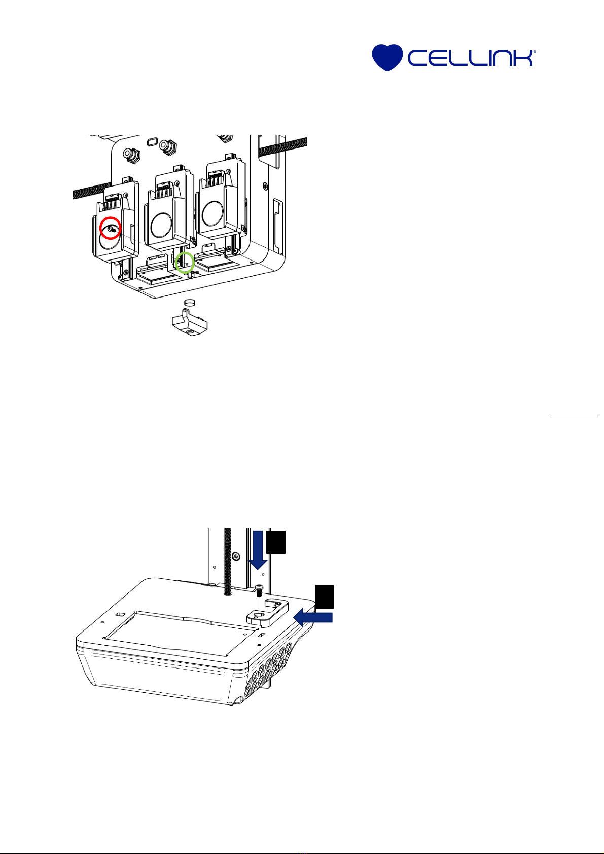
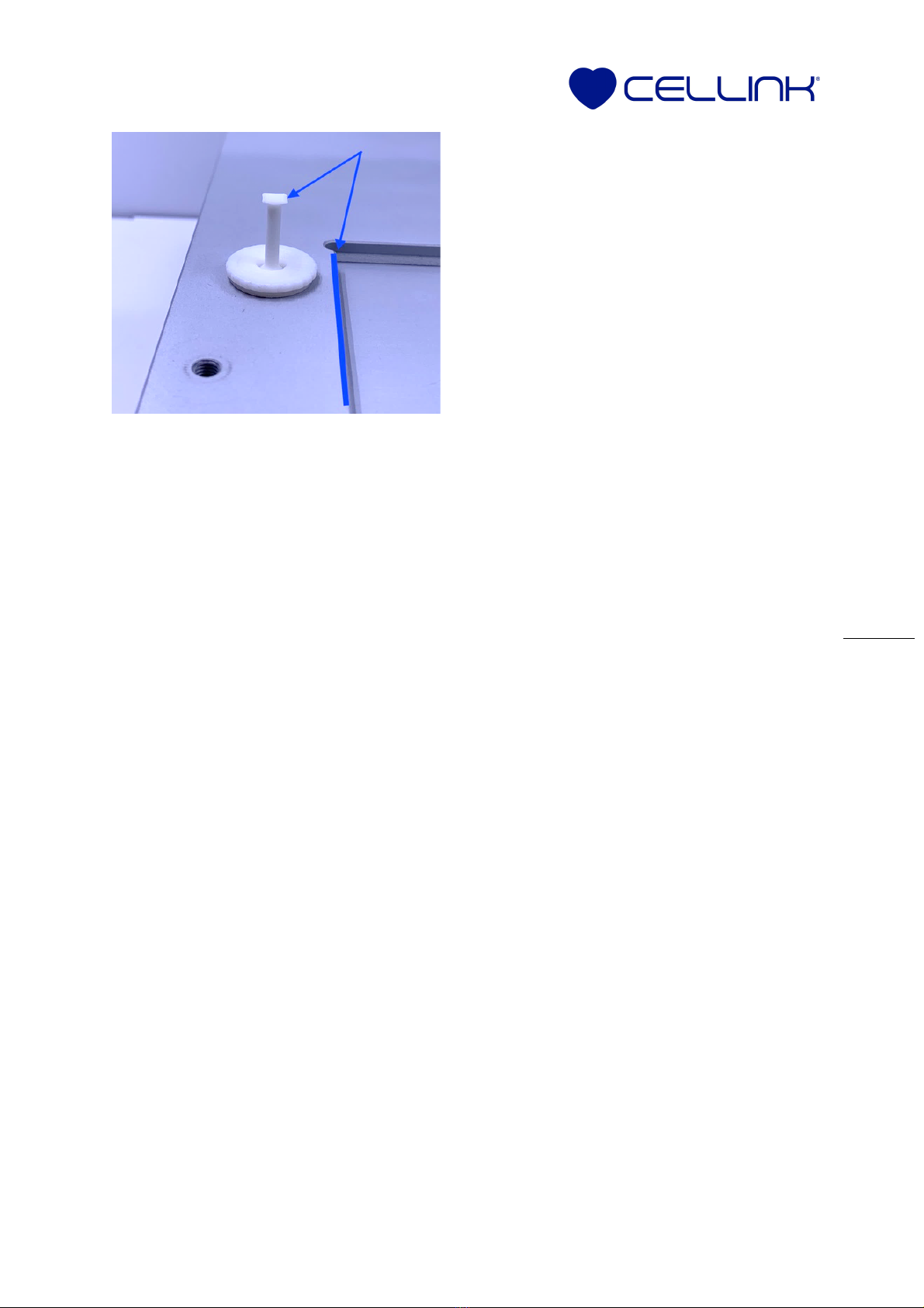
1. Visually inspect the following endstops:
- The surface probe endstop. This is the red button switch under the print box.
- The Z-probe endstop. This is the metal or plastic switch on the top-right side of
the print bed.
- The X-Y endstops. These are in the hole on the top-left side of the print bed.
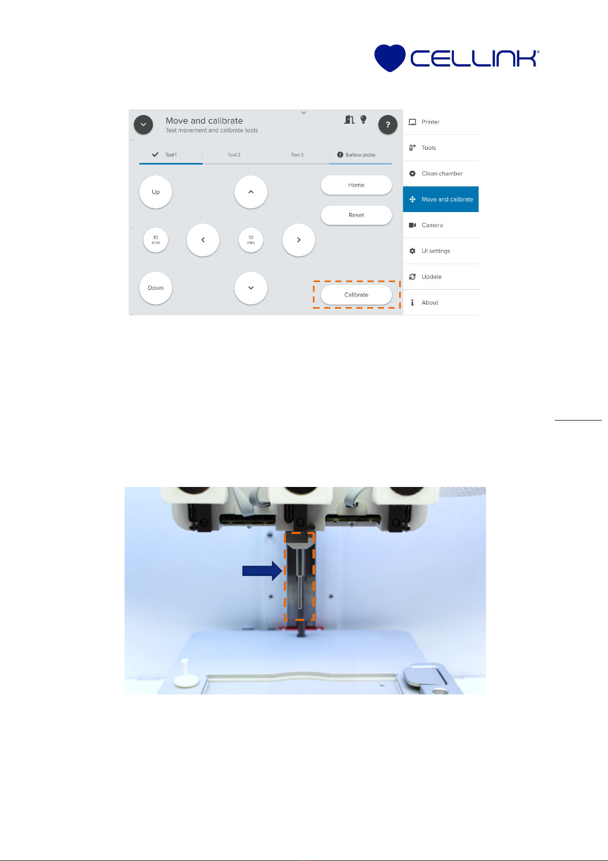
2. To check for proper activation of the autocalibration endstops, navigate to the
Utilities menu. Select Printer, Hardware then Sensors.
a. Press your finger on the surface probe endstop. Verify that the status light
turns blue to indicate a status change for the surface probe.
b. Press your finger on the Z probe. Verify that the status light turns blue to
indicate a status change for the Z-probe.
c. Use a cartridge with a nozzle attached to reach inside the hole on the top-left
side of the print bed and activate the X and Y endstops. Verify that the status
light turns blue to indicate a status change for the X-probe and Y-probe.

Boston, U.S.
100 Franklin St.,
Boston, MA 02110
Gothenburg, Sweden
Arvid Wallgrens Backe 20,
Gothenburg, 41346
Virginia, U.S.
2000 Kraft Dr., Suite 2125
Blacksburg, VA 24060
Kyoto, Japan
46-29 Yoshida-Shimo Adachi-
cho, Sakyo-ku, Kyoto
www.cellink.com | +1 (833) CELLINK
4
NOTE: If any endstop components are misaligned, absent or not activating, contact the
CELLINK Support team at support@cellink.com.

Boston, U.S.
100 Franklin St.,
Boston, MA 02110
Gothenburg, Sweden
Arvid Wallgrens Backe 20,
Gothenburg, 41346
Virginia, U.S.
2000 Kraft Dr., Suite 2125
Blacksburg, VA 24060
Kyoto, Japan
46-29 Yoshida-Shimo Adachi-
cho, Sakyo-ku, Kyoto
www.cellink.com | +1 (833) CELLINK
5
Installation of BIO X Autocalibration Kit
Step 1: Installing the surface probe station
Step 2: Installing the Z-probe station
NOTE: Be careful not to damage the Z probe endstop during the hardware installation.
Excessive force can cause the lever to detach.
1. Turn the BIO X off and remove all
printheads.
2. Unscrew the bottom mechanical endstop
screw of the second printhead, labeled by
the green circle in the diagram.
3. Remove the spacer and keep the M2
screw, labeled by the red circle in the
diagram.
4. Insert the magnet into the surface probe
stabilizer. Polarity does not matter when
inserting the magnet.
5. Align the surface probe stabilizer and
magnet such that the surface probe
endstop is directly on top of the magnet.
6. Being careful not to bend the red switch,
press the stabilizer up and toward the
back of the printer.
7. Insert the M2 screw in the surface probe
stabilizer. Tighten it, making sure to not
overtighten.
1. Align the slot of the Z-station
base with the right M4 hole in
the print bed.
2. Place the supplied M4 screw into
the hole. Do not tighten.
3. Press the Z-station base firmly to
the left to align it with the print
bed.
4. Maintain pressure and tighten
the M4 screw.
1
3

Boston, U.S.
100 Franklin St.,
Boston, MA 02110
Gothenburg, Sweden
Arvid Wallgrens Backe 20,
Gothenburg, 41346
Virginia, U.S.
2000 Kraft Dr., Suite 2125
Blacksburg, VA 24060
Kyoto, Japan
46-29 Yoshida-Shimo Adachi-
cho, Sakyo-ku, Kyoto
www.cellink.com | +1 (833) CELLINK
6
Step 3: Installing the XY printhead calibration lever
5. Insert the Z-probe plate as shown.
It will click into place and pivot
freely, triggering the Z-probe
endstop when pressed down and
resetting when released.
1. Turn the BIO X on and navigate to the
Utilities
menu. Select
Printer
,
Hardware
then
Sensors.
2. Align the left and right edges of the
XY lever to be parallel with the print
bed edges along the Y-axis
3. Gently push the XY lever into the XY
station slot.

Boston, U.S.
100 Franklin St.,
Boston, MA 02110
Gothenburg, Sweden
Arvid Wallgrens Backe 20,
Gothenburg, 41346
Virginia, U.S.
2000 Kraft Dr., Suite 2125
Blacksburg, VA 24060
Kyoto, Japan
46-29 Yoshida-Shimo Adachi-
cho, Sakyo-ku, Kyoto
www.cellink.com | +1 (833) CELLINK
7
Quick-start guide
Inserting and removing the surface probe
1. Insert the surface probe wide-side-up into the surface probe stabilizer. The magnet
will hold it in place.
2. To remove after ABL or autocalibration, pull it away from the magnet and store it
safely.
Machine calibration
NOTE: Perform machine calibration before using any of the automatic calibration features.
Recalibrate after each software update or if experiencing calibration issues with automatic
calibration.
HeartOS 1.7+ directory: Utilities -> Move and calibrate.
Start by calibrating the printheads following these steps
1. Load any of the compatible printheads in the three printhead mounts (3cc Pneumatic,
10cc Pneumatic and Temperature-controlled) and place cartridges with conical
nozzles inside the printhead. Turn the screw to secure the cartridges in place.
If any X or Y probe sensors are triggered after
installing the XY lever, follow these steps:
1. Turn the round base of the XY lever one
quarter turn clockwise to trigger the X and Y
probe sensors. Continue turning until X and Y
probes are marked as OFF.
2. Move the XY printhead calibration lever to
trigger the X and Y probes and manually
confirm that they are triggered. The XY lever
should automatically return to its center
position.

Boston, U.S.
100 Franklin St.,
Boston, MA 02110
Gothenburg, Sweden
Arvid Wallgrens Backe 20,
Gothenburg, 41346
Virginia, U.S.
2000 Kraft Dr., Suite 2125
Blacksburg, VA 24060
Kyoto, Japan
46-29 Yoshida-Shimo Adachi-
cho, Sakyo-ku, Kyoto
www.cellink.com | +1 (833) CELLINK
8
2. Navigate to Utilities. Select Move and calibrate.
3. For Tool 1, select Home, and wait for homing cycle to run.
4. Use the arrows on the screen to move the printhead. Place the nozzle of Printhead 1
on top of the XY printhead calibration lever, as centered as possible. Focus on the X
and Y alignments; ignore the Z alignment as it does not need to touch in the Z
direction.
a. Cross-reference with correct and incorrect calibration positions pictured
below.

Boston, U.S.
100 Franklin St.,
Boston, MA 02110
Gothenburg, Sweden
Arvid Wallgrens Backe 20,
Gothenburg, 41346
Virginia, U.S.
2000 Kraft Dr., Suite 2125
Blacksburg, VA 24060
Kyoto, Japan
46-29 Yoshida-Shimo Adachi-
cho, Sakyo-ku, Kyoto
www.cellink.com | +1 (833) CELLINK
9
5. Select Calibrate. Printhead 1 will calibrate automatically.
6. Repeat steps 4 and 5 for Tool 2 and Tool 3. There is no need to home the axes again.
Proceed to calibrate the surface probe following these steps:
1. Make sure the surface probe is attached.

Boston, U.S.
100 Franklin St.,
Boston, MA 02110
Gothenburg, Sweden
Arvid Wallgrens Backe 20,
Gothenburg, 41346
Virginia, U.S.
2000 Kraft Dr., Suite 2125
Blacksburg, VA 24060
Kyoto, Japan
46-29 Yoshida-Shimo Adachi-
cho, Sakyo-ku, Kyoto
www.cellink.com | +1 (833) CELLINK
10
2. Select the Surface Probe tab under Utilities -> Move and calibrate, as shown in the
image below.
3. Home the axes and move the surface probe so that it hovers over the XY printhead
calibration lever, as centered as possible. Focus on the X and Y alignments; ignore the
Z alignment as it does not need to touch in the Z direction.
a. Cross-reference with correct and incorrect calibration positions pictured
below.

Boston, U.S.
100 Franklin St.,
Boston, MA 02110
Gothenburg, Sweden
Arvid Wallgrens Backe 20,
Gothenburg, 41346
Virginia, U.S.
2000 Kraft Dr., Suite 2125
Blacksburg, VA 24060
Kyoto, Japan
46-29 Yoshida-Shimo Adachi-
cho, Sakyo-ku, Kyoto
www.cellink.com | +1 (833) CELLINK
11
4. Select Calibrate. The surface probe will calibrate automatically.
5. Remove the surface probe. Remember to remove the probe when autocalibration is
not running.

Boston, U.S.
100 Franklin St.,
Boston, MA 02110
Gothenburg, Sweden
Arvid Wallgrens Backe 20,
Gothenburg, 41346
Virginia, U.S.
2000 Kraft Dr., Suite 2125
Blacksburg, VA 24060
Kyoto, Japan
46-29 Yoshida-Shimo Adachi-
cho, Sakyo-ku, Kyoto
www.cellink.com | +1 (833) CELLINK
12
Enabling automatic bed leveling (ABL) for a print
WARNING. Do NOT leave your BIO X unsupervised while it runs ABL. Be prepared to turn
off your BIO X if ABL fails. Leaving your BIO X unsupervised during the ABL process risks
damage to your machine.
HeartOS 1.7+:
Bioprint-> Print -> Print -> Calibrate -> Automatic bed-leveling
1. If you would like to run automatic bed- and surface-leveling only, begin the
bioprinting process as usual. Select a model and surface.
2. Enter your printer and layer settings.
3. Navigate to the Print tab. Review your parameters and optionally save the protocol.
4. Select Print.
5. Once in the print page, press Calibrate and select Automatic bed-leveling.

Boston, U.S.
100 Franklin St.,
Boston, MA 02110
Gothenburg, Sweden
Arvid Wallgrens Backe 20,
Gothenburg, 41346
Virginia, U.S.
2000 Kraft Dr., Suite 2125
Blacksburg, VA 24060
Kyoto, Japan
46-29 Yoshida-Shimo Adachi-
cho, Sakyo-ku, Kyoto
www.cellink.com | +1 (833) CELLINK
13
6. A message will appear prompting you to attach the surface probe. Attach the probe
and select Continue.
7. A progress screen will appear. If necessary, press Abort to cancel the procedure at
any time. After canceling the procedure or completing the ABL process, the system
will return to the calibration method menu.
8. Use automatic calibration or remove the probe for manual calibration.

Boston, U.S.
100 Franklin St.,
Boston, MA 02110
Gothenburg, Sweden
Arvid Wallgrens Backe 20,
Gothenburg, 41346
Virginia, U.S.
2000 Kraft Dr., Suite 2125
Blacksburg, VA 24060
Kyoto, Japan
46-29 Yoshida-Shimo Adachi-
cho, Sakyo-ku, Kyoto
www.cellink.com | +1 (833) CELLINK
14
NOTE: Keeping the surface probe attached while printing may damage the printed construct.
Enabling automatic calibration for a print
WARNING. Do NOT leave your BIO X unsupervised while it runs automatic calibration. Be
prepared to turn off your BIO X in the event of automatic calibration failure. Leaving your
BIO X unsupervised during the automatic calibration process risks damage to your machine.
NOTE: Automatic calibration is only supported for the 3cc Pneumatic, 10cc Pneumatic and
Temperature-controlled Printheads.
HeartOS 1.7+:
Bioprint-> Print -> Print -> Calibrate -> Automatic Calibration
1. If you would like to run automatic bed-leveling and automatic calibration, start the
bioprinting process as usual. Select a model and a surface and enter your printer and
layer settings.
2. Go to the Print tab. Review your parameters and optionally save the protocol.
3. Select Print.
4. Press Calibrate in the print page. Select Automatic calibration.

Boston, U.S.
100 Franklin St.,
Boston, MA 02110
Gothenburg, Sweden
Arvid Wallgrens Backe 20,
Gothenburg, 41346
Virginia, U.S.
2000 Kraft Dr., Suite 2125
Blacksburg, VA 24060
Kyoto, Japan
46-29 Yoshida-Shimo Adachi-
cho, Sakyo-ku, Kyoto
www.cellink.com | +1 (833) CELLINK
15
5. A message will appear prompting you to attach the surface probe. Attach the probe
and select Continue.
6. Ensure the XY printhead calibration lever is positioned in a straight vertical position.
Clear the bed of any tall objects.
7. Verify all hardware components are ready.
8. Select Start to begin the calibration process.

Boston, U.S.
100 Franklin St.,
Boston, MA 02110
Gothenburg, Sweden
Arvid Wallgrens Backe 20,
Gothenburg, 41346
Virginia, U.S.
2000 Kraft Dr., Suite 2125
Blacksburg, VA 24060
Kyoto, Japan
46-29 Yoshida-Shimo Adachi-
cho, Sakyo-ku, Kyoto
www.cellink.com | +1 (833) CELLINK
16
9. After a homing cycle, automatic calibration will begin and a progress screen will
appear. If necessary, press Abort to cancel the procedure at any time.
10. After the automatic calibration process is complete, a message will appear prompting
you to remove the surface probe. Remove the surface probe and select Close to
return to the print menu.

Boston, U.S.
100 Franklin St.,
Boston, MA 02110
Gothenburg, Sweden
Arvid Wallgrens Backe 20,
Gothenburg, 41346
Virginia, U.S.
2000 Kraft Dr., Suite 2125
Blacksburg, VA 24060
Kyoto, Japan
46-29 Yoshida-Shimo Adachi-
cho, Sakyo-ku, Kyoto
www.cellink.com | +1 (833) CELLINK
17
11. Press Start to proceed to bioprinting.
Removing autocalibration hardware for packing
When packing your BIO X for transport, remove the following parts:
• XY printhead calibration lever.
• Z station base.
• Surface probe.
Note: Tools are not required to remove these parts. Ensure they are stored safely during
transport.
This manual suits for next models
1
Table of contents
Other Cellink Printer Accessories manuals
Popular Printer Accessories manuals by other brands

Pitney Bowes
Pitney Bowes SendPro Desktop SendKit Installation instruction

Epson
Epson T033120 Product information sheet

Epson
Epson C823642 - Enet Print Server Type B Multi Protocol... Administrator's manual

Star Micronics
Star Micronics TSP700 Series Attachment instructions

VASTEX
VASTEX E-200 series Assembly and operation instructions

TonerRefillKits
TonerRefillKits brother ReChargX RX350 instructions