Cembre PCMD-FC User manual

1
MACHINE FOR PANDROL
"FASTCLIP" FASTENING
PCMD-FC
ENGLISH OPERATION AND MAINTENANCE MANUAL
16 M 197 E

2
INDEX page
1. General characteristics ....................................................................................................................................................... 4
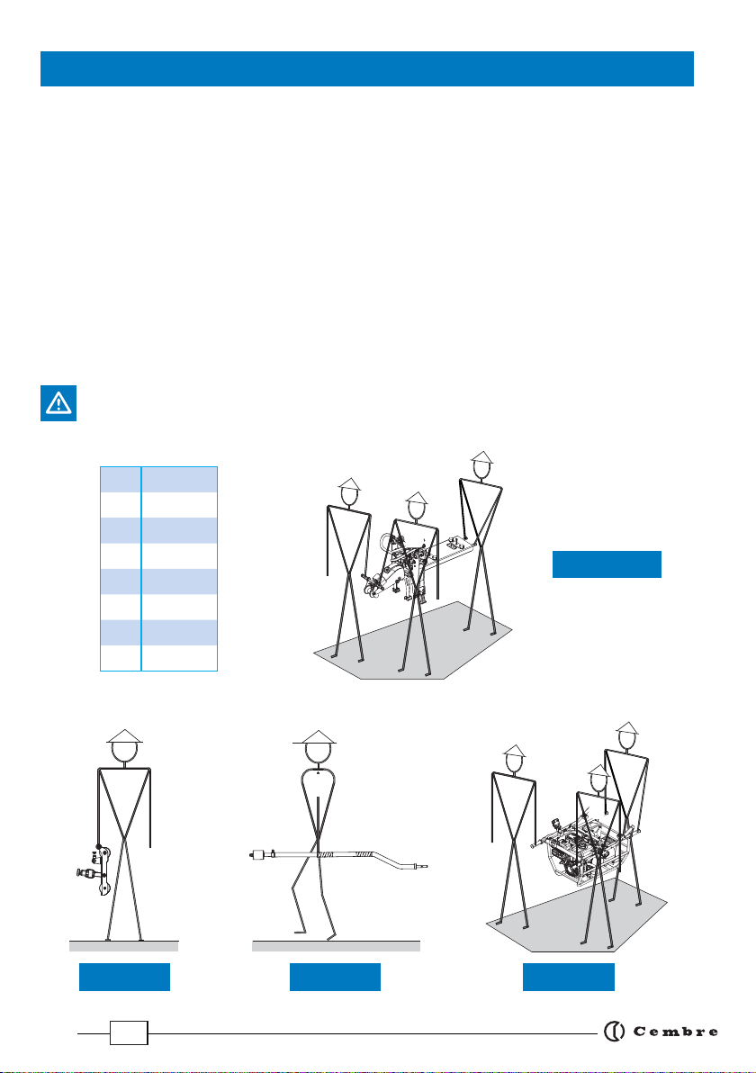
2. Unpacking .............................................................................................................................................................................. 5
2.1 Transporting the machine ................................................................................................................................................ 5
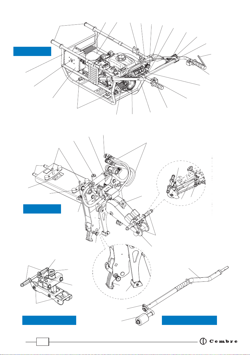
3. Description of the machine ............................................................................................................................................. 6
4. Instructions for use ............................................................................................................................................................. 8
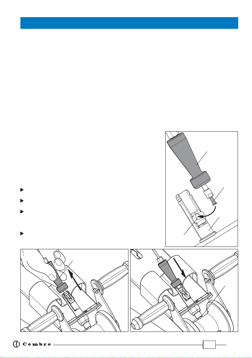
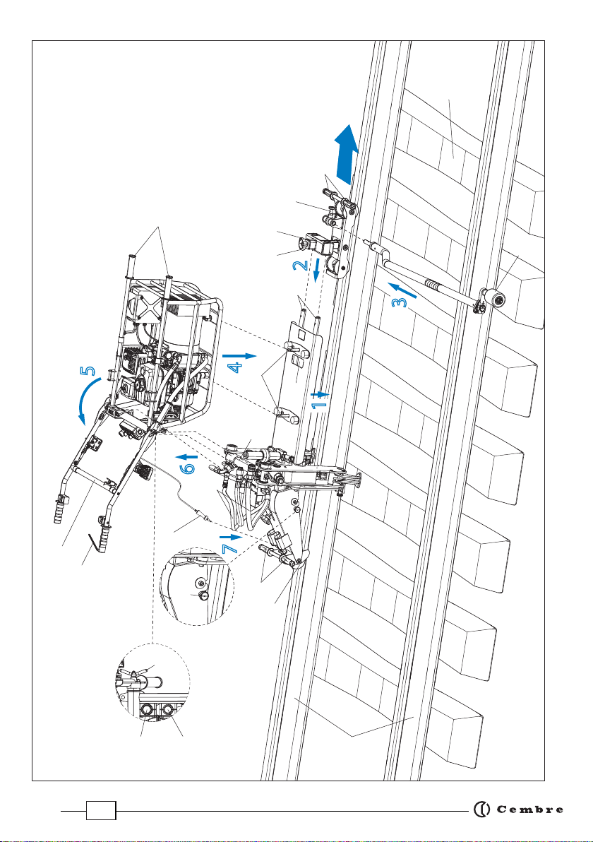
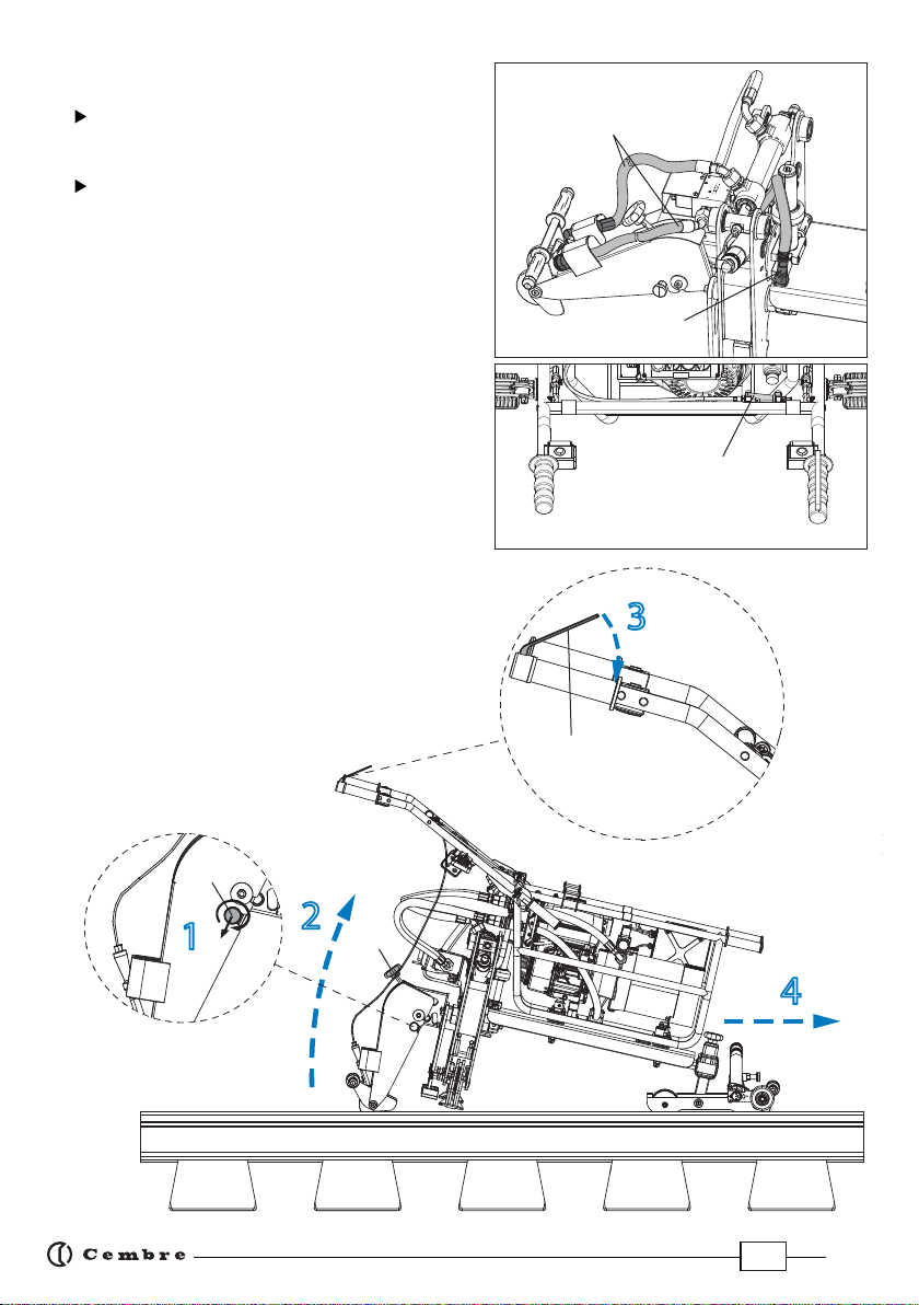
4.1 Assembling the machine ................................................................................................................................................. 8
4.1.1 Braking device ...................................................................................................................................................................... 8
4.2 Disassembling the machine ........................................................................................................................................... 10
4.3 Moving the machine .......................................................................................................................................................... 10
4.4 Controls ................................................................................................................................................................................... 11
4.5 Description of the Pandrol Fast clip .............................................................................................................................. 12
4.6 Description of the Pandrol FE clip ................................................................................................................................. 13
4.7 Description of the Pandrol FCX clip .............................................................................................................................. 14
4.8 Preliminary machine adjustments ................................................................................................................................ 15
4.8.1 Adjusting the height of the front of the machine .................................................................................................... 15
4.8.2 Stable support of both insertion teeth ........................................................................................................................ 15
4.8.3 Adjusting the piston for lifting sleepers ...................................................................................................................... 16
4.8.4 Adjusting the clamp position .......................................................................................................................................... 16
4.9 Operation ................................................................................................................................................................................17
4.9.1 Inserting clips ........................................................................................................................................................................ 17
4.9.2 Extracting clips ..................................................................................................................................................................... 18
4.9.3 Adjusting the contrast foot for extraction .................................................................................................................. 18
5. Adjusting the piston stroke .............................................................................................................................................. 19
5.1 Adjusting the piston stroke for clip insertion ............................................................................................................ 19
5.2 Adjusting the piston stroke for clip extraction ......................................................................................................... 20
5.2.1 Parking position ................................................................................................................................................................... 20
5.2.2 Insulator change position ................................................................................................................................................ 20
6. Display ..................................................................................................................................................................................... 21
6.1 Information screens ............................................................................................................................................................ 21
6.2 Warnings ................................................................................................................................................................................. 21
6.3 Errors ........................................................................................................................................................................................ 22
7. Starting the engine ............................................................................................................................................................. 23
8. Maintenance ......................................................................................................................................................................... 24
8.1 Routine maintenance of the machine ......................................................................................................................... 24
8.1.1 Maintenance of braking device ...................................................................................................................................... 24
8.1.2 Maintenance of clamp unit .............................................................................................................................................. 25
8.1.3 Topping up the oil in the hydraulic pump .................................................................................................................. 26
8.1.4 Replacing the hydraulic pump oil lter ......................................................................................................................... 26
8.1.5 Adjusting the work lights ................................................................................................................................................. 26
8.1.6 Changing the gas springs ................................................................................................................................................. 27
8.2 Routine maintenance of the engine ............................................................................................................................. 27
8.3 Long periods of inactivity ................................................................................................................................................. 27
9. Return to Cembre for overhaul .................................................................................................................................... 30

3
-
Before using the machine read the instructions contained in this manual carefully.
SAVE THESE INSTRUCTIONS: this manual contains important safety and operating
instructions for the machine.
- During operation keep your hands and all other persons outside the danger area.
- Always use Personal Protective Equipment such as is normally required by your em-
ployer and/or appropriate to your sector of operation.
- Always follow fuelling and refuelling practices and procedures normally required by
your employer and/or appropriate to your sector of operation.
- Only authorised personnel shall start, operate and maintain the machine.
- The design or conguration of the machine shall not be modied other than by
Cembre.
- Cannot be used over switches and crossings.
- Not to be used near live d.c. conductor rail.
- Not to be used for any purpose other than for which machine is designed.
- Do not exceed walking pace when moving the machine along the rail.
WARNINGS

4
Application range
suitable for the insertion or extraction of PANDROL* FE, FC
and FCX clips on standard gauge sleepers (1435 mm)
Developed force (single clamp)
N
38.000
Dimensions
see Fig. 30 page 29
Resistance between rail and wheel
MΩ
≥ 1
Weight
Complete machine
kg
143
Pump unit
kg
59
Clamp unit
kg
69
Carriage
kg
9
3rd wheel bar
kg
5
Combustion engine
Type 4-stroke, overhead valve, single cylinder
Model Honda GX200 UT-SMCR OH
Displacement cm³ 196 cm³
Power kW 4.1 (5.6)
Revs. rpm 3600
Exhaust emissions the engine is certied Euro 2 and meets U.S. EPA EXH/EVP
and CALIFORNIA SORE EXH/EVP REGS FOR 2013
Fuel unleaded regular grade petrol
Tank capacity lt 3,1
Recommended oil SAE 10W-30 (0,6 litres)
Start by rope pull with automatic rewind
Hydraulic pump
Max. pressure MPa 25
Oil supply 35 litres/minute
Oil capacity kg 4,5
Speed rpm 3500
Recommended oil kg (lbs) PANOLIN HLP SYNTH E68
Acoustic noise (1)
dB
LpA 86,4 (A) LpCPeak <130 (C) LWA 101,0 (A)
Vibration (2) m/s24,63 max.
1. GENERAL CHARACTERISTICS
(*) "Pandrol Fastclip" is a Pandrol Ltd trademark.
(1) Directive 2006/42/EC, annexe 1, point 1.7.4.2 letter u
LpA = weighted continuous acoustic pressure level equivalent.
LpCPeak = maximum value of the weighted acoustic displacement
pressure at the work place.
LWA = acoustic power level emitted by the machine.
(2) Directive 2006/42/EC, annexe 1, point 2.2.1.1
Weighted root mean square in frequency of the acceleration
theupperlimbsareexposedtoforeachbiodynamicreference
axis. Tests carried out in compliance with the indications
containedin ENISO5349-1/2Standard,andunderoperating
conditions much more severe than those normally found.

5
2. UNPACKING THE MACHINE
To reduce overall dimensions and weight during transport, the machine is supplied disassembled in sturdy
wooden crates.
The four component units are easily reassembled (Ref. to Fig. 1):
– Pump unit: combustion engine/hydraulic pump for clamp operation.
– Clamp unit: for inserting and extracting clips.
– Carriage: for supporting and moving the machine along the track.
– 3rd wheel bar: forstabilityandverticalpositioning(thethirdwheel(47)is supplieddisconnected
from the bar (49).
2.1) Transporting the machine
The four units are well balanced for easy transportation in accordance with the table and diagrams in Fig. 1. For
uniform weight distribution when carrying the pump and clamp units, always use the transportation handles
provided.
Ensure appropriate Personal Protective Equipment is used to avoid injury during transportation.
A
C
B
A
23 kg
B
23 kg
C
23 kg
D
9 kg
E
5 kg
F
19 kg
G
19 kg
H
21 kg
DF
CR-PCMD PU-PCMD
SC-PCMD
G
H
FIG. 1
CUFC-PCMD
E

6
3. DESCRIPTION OF THE MACHINE
01
TRANSPORTATION HANDLES
02
OIL COOLING FINS
03
HYDRAULIC PUMP
04
WORKLIGHT ON/OFF SWITCH
05
ELECTRICAL CONNECTOR SOCKET
06
QUICK RELEASE FEMALE AUTOMATIC HYDRAULIC COUPLER
07
HANDLEBAR LOCKING WINGNUT
08
QUICK RELEASE MALE AUTOMATIC HYDRAULIC COUPLER
09
BRAKE RELEASE CONNECTOR HOLDER (WHEN NOT IN USE)
10
WORKLIGHT
11
HANDLEBAR
12
BRAKE RELEASE LEVER
13
CLAMP DRIVE BUTTON FOR INSERTION/EXTRACTION
14
UPLIFT SETTING BUTTON
15
CLAMP CONTROL SWITCH
16
CLAMP RETURN BUTTON
17
STOP/EMERGENCY BUTTON
18
ENGINE
19
WORKLIGHT
20
PUMP UNIT FASTENING/RELEASE KNOB
21
ELECTRICAL TERMINAL BOX
22
DISPLAY
23
FRAME
24
TRANSPORT HANDLE
25
CLAMP UNIT LOCATING PINS
26
PUMP UNIT LOCATING PINS
27
SLEEPER LIFT PISTON
28
INSERT/EXTRACT PISTON
29
ELECTRICAL CONNECTOR
30
HYDRAULIC FLEXIBLE HOSES
31
MACHINE LIFT HEIGHT ADJUSTER
32
TRANSPORTATION HANDLES
33
REAR ARM WHEEL
34
EXTRACTION HOOK FASTENING/RELEASE KNOB
35
HEIGHT SETTING DEVICE
36
RAM STROKE ADJUSTMENT RING NUT
37
BRAKE RELEASE CONNECTOR SOCKET
38
GAS SPRING
39
REAR ARM WHEEL LOCK/RELEASE KNOB
40
INSERTION/EXTRACTION TOOTH
41
CONTRAST FOOT
42
TRANSPORTATION HANDLES
43
3rd WHEEL ARM FASTENING/RELEASE KNOB
44
FRONT HEIGHT ADJUSTMENT KNOB
45
CLAMP UNIT FASTENING/RELEASE KNOB
46
CARRIAGE WHEELS
47
SUPPORT WHEEL
48
SUPPORT WHEEL ADJUSTMENT LEVER
49
ARM

7
26
25
27
29
30
39
32
33
35
34
3rd WHEEL BAR
CLAMP UNIT
CARRIAGE
46
42
45
43
37
PUMP UNIT
38
41
40
31
44
28
24
01 03 04 06 08
10
13
18
19
22
23
14
15
FIG. 2
12
02
20 16
09
17
11
07
05
21
36
49
47
48

8
4.1) Assembling the machine
Select the rail to be worked on and the direction of operation, then assemble the machine as follows, referring
to Fig. 4:
1 –With knob (09) engaged and wheel (33) blocked, lift the clamp unit by means of the handles (24 & 32) and
rest this on the selected rail, positioning it at a sleeper for stability.
2 – Rest the support carriage on the track then pull and turn the fastening/release knobs (45).
Lift the clamp unit by the handle (24) and locate pins (25) fully into their carriage housings as far as the
stop. Release knob (45) to lock the clamp unit.
3 –Pull and turn knob (43), insert the 3rd wheel bar in the carriage housing as far as the stop, aligning the hole
in the end of the arm with the pin knob.
Release knob (43) so wheel (47) can act as a support on the opposite rail and make the assembly stable
and able to slide along the rail. The arm can be tted to the carriage from either side for convenience in
selecting the direction of work.
4 –Pull and turn knobs (20) at the base of the pump unit. Lift the pump unit by handles (01) and handlebar
(11). Rest the pump unit on the clamp unit and align pins (26) with the relevant locating holes on the
under side of the pump unit. Release the knobs to lock.
5 –Unscrew handlebar locking wingnut (07) and rotate handlebar (11)
to a confortable position, tighten the wingnut fully to lock the handle.
6 –Plug electrical connector (29) into socket (05).
Attach exible hydraulic hoses (30) by means of the quick cou-
plings to the respective sockets (06 & 08) on the clamp unit.
7 –Attach brake release (09) (Ref. to § 4.1.1) and adjust the gas springs
of the rear wheel arm using knob (31).
4.1.1) Braking system (Ref. to Fig. 3a, 3b, 3c, 4)
To move the machine along the rail, it is necessary to attach brake release
(09) to socket (37) on the rear arm as follows:
Introduce end part (A) into slot seat (B) located above the wheel of the
rear support arm (Ref. to Fig. 3a).
Pullhandle(C)upwards,releaseitinpositionthenpushuntil itislocked
(Ref. to Fig. 3b and c).
Press lever (12) to verify the correct engagement and disengagement
of pin (P) from the wheel (Ref. to Fig. 3c).
During disassembly of the machine, before removal of the pump unit,
the brake release must be detached as follows:
Pull handle (C) and detach end (A) from slot seat (B).
A
B
FIG. 3a
09
FIG. 3b FIG. 3c
4. INSTRUCTIONS FOR USE
37
C
P

9
4
2
7
6
3
5
1
FIG. 4
01
11
09
39
32
33
30
43
25
26
47
RAILS
SLEEPER
DIRECTION OF
MOVEMENT
24
42
45
12
06
08
07
44
31 29

10
4.2) Disassembling the machine
To disassemble the machine:
First lower the rear support arm and lock with pin
(39), block wheel (33) then reverse the process de-
scribed in § 4.1.
On the pump unit, disconnect/detach electrical con-
nector (29), hydraulic hoses (30) (Ref to Fig. 5a) and
brake release (09) (Ref to Fig. 5b), placing the hoses in
their supports in the clamp unit and the brake release
in its support on the handlebar.
NOTE: Under normal conditions, the time taken to
removethemachinefromtherailisapproximately
60 seconds.
4.3) Moving the machine
To move the machine along the rail, the rear arm must
be raised to prevent the clamps knocking against the
Fastclip as follows:
1 –Pulland turn knob (39).Thewheel arm willbe freed
(Ref. to Fig. 6).
2 – Lift theunitby thehandles;the two gassprings will
facilitatefulllifting;thetwospringscanbeadjusted
using knob (31), turning it clockwise for stier
springs, anticlockwise for softer.
3 – Press brake release lever (12) against handlebar
(11).
4 – Push the machine along the rail.
3
2
4
1
FIG. 6
12
39
31
09
FIG. 5b
FIG. 5a
30
29

11
4.4) Controls
When gripping handlebar (11), the operator can easily access all the unit controls and, more specically:
Worklights ON/OFF switch (04): two high eciency LED lights allow the clamp area to be eectively lit in
poor light conditions and at night.
Brakerelease lever(12): forsafetyreasonsthemachineis equippedwith a"deadman's"brakingsystem onthe
rear wheel. It is only possible to release the brake by pressing the lever (12), allowing the machine to move
along the rail.
Clamp operation button (13): enables operation of the clamps according to the mode selected with switch
(15).
Settings button (14): enables the machine to memorise the clamp position set for sleeper lifting.
Clamp control selector (15): allows the selection of insertion "IN" or extraction "OUT" of the clamps.
Clamp return button (16): enables the clamps to be brought back to their starting position.
With clamp control selector (15) on “OUT” it enables insertion of the clamps at a lower speed.
Stop/emergency button (17) in a very visible position and easy to operate to stop the machine normally
and in case of an emergency.
NOTE: when this button is pressed it remains in OFF position. To start the engine, the button should be turned
clockwise so that it lifts automatically into the ON position.
The engine will not start unless the red button (17) is lifted.
FIG. 7
16
13
12
04
17 15 14
11

12
Fastclip
Toe insulator
Shoulder
Side post insulator
4.5) Description of the Pandrol Fastclip
FASTCLIPS have 3 positions:
PARKING POSITION:
All components are captive.
INSTALLED POSITION:
The Fastclip holds the rail.
INSULATOR CHANGE POSITION:
The Fastclip is withdrawn to the rear detent to
facilitate side post insulator removal.
FIG. 8 – FASTCLIP

13
4.6) Description of the Pandrol FE clip
FE CLIPS have 3 positions:
PARKING POSITION:
All components are captive.
INSTALLED POSITION:
The FE clip holds the rail.
INSULATOR CHANGE POSITION:
The FE clip is fully extracted and the
insulator can be removed.
Side post insulator
Toe insulator
FE clip
Shoulder
FIG. 9 – FE CLIP

14
4.7) Description of the Pandrol FCX clip
FCX CLIPS have 3 positions:
FCX clip
Toe insulator
Shoulder
Side post insulator
PARKING POSITION:
All components are captive.
INSTALLED POSITION:
The FCX clip holds the rail.
INSULATOR CHANGE POSITION:
The FCX clip is withdrawn to the rear stop to
facilitate side post insulator removal.
FIG. 10 – FCX CLIP

15
4.8) Preliminary machine adjustments
MACHINE ADJUSTMENT IS ESSENTIAL TO ENSURE CORRECT OPERATION.
SOME ADJUSTMENTS REQUIRE THE ENGINE TO RUN.
SWITCH OFF THE ENGINE WHEN MAKING MANUAL ADJUSTMENTS TO THE CLAMPS AND LIFTING
PISTON.
The PCMD-FC is extremely versatile and adaptable to the many operating situations to be found along a railway
line (dierent types of rails, 60E1 etc. with dierent ange heights and widths, dierent types of clips, sleepers
and chairs. For this reason, before use, some initial adjustment will be required to dene the correct machine
setup during work.
Follow the following preliminary adjustments:
4.8.1) Adjusting the height of the front of the machine
Fully lower the machine so it is resting on the
sleeper.
Line up the side of the machine so that the
clamp unit is parallel with the upper surface of
the railhead. If this is not the case, adjust knob
(44) on the carriage (Ref. to Fig.11).
To lift the machine turn knob (44) anti-clocwise.
To lower the machine turn it clockwise.
The measuring scale will facilitate adjustment
by precisely dening the correct position of the
machine.
4.8.2) Stable support of both insertion teeth
Both insertion teeth (40) must be supported equally on the surface of the sleeper. If this is not the case, proceed
to vertically adjust the machine by turning the support wheel on the 3rd wheel bar (47):
Lower the machine completely with the teeth resting on the surface of the sleeper.
Unscrew the quick release handle (48).
Lower or raise the bar (49) to change the vertical angle of the machine and achieve correct alignment.
After making adjustments, fully retighten handle (48).
FIG. 11
0
1
2
3
4
5
45
44
47
49
48
FIG. 12
40 40

16
4.8.3) Adjusting the piston for lifting sleepers
Procedure to be carried out on the clip in the "installation position".
When manually adjusting the lifting piston ensure THE ENGINE IS SWITCHED OFF.
The lifting piston must be adjusted correctly using the supplied gauge, otherwise the machine could
break the insulators or insert the clips Incorrectly.
Turn the clamp control selector (15) to the “OUT” position; press button (16) repeatedly with short pulses to
put the clamps into contact with the clips already in the “installation position”.
Make sure that the lifting piston (27) is fully up in the starting position.
Place the Height Setting Device (HSD) (35) from the magnetic side on top of the rail in correspondence with
the piston. With a 17 mm wrench, block the piston (27) and loosen
the nut (D) with a 18 mm wrench.
Rotate the threaded rod so that the foot is resting on
the gauge and then tighten the nut (D) again.
Remove the HSD (35) and put it back
in its seat.
4.8.4) Adjusting the clamp position
Procedure to be carried out on the clip in "parked position".
Start the engine (see § 7).
Push the machine so that it is in line with the clip to be operated on
(see § 4.3).
Position the clamps with the insertion teeth (40) in the open position
(Ref. to Fig. 13b).
Turn the clamp control selector (15) to the “OUT” position.
Press button (16) repeatedly with short pulses to make the clamps
slowly advance towards the clips.
Bring the correctly centred insertion teeth into contact with the clip without the clips being inserted.
Press and hold button (14) to memorise the position.
Three worklight ashes conrm that the position has been saved.
Turn the clamp control selector (15) back to the "IN" position.
40
FIG. 13b
FIG. 13a
35
27
D
17 mm
18 mm

17
4.9) Operation
Before use, always check:
Integrity of the machine.
The correct coupling of the units making up the machine.
Correct connection of the quick couplings and braking system.
Correct level of oil in pump.
For any oil leaks in the hydraulic circuit (hoses, pump).
Flexible hoses are in good condition and show no signs of wear or crushing.
Protection devices in the clamp areas are rm and show no signs of damage.
That the engine fuel tank cap is tight. Petrol is highly inammable and can explode.
When manually adjusting the clamps ensure THE ENGINE IS SWITCHED OFF.
Start the engine (see § 7).
4.9.1) Inserting clips
Make sure the locking knob (39) of the rear wheel is released (see § 4.3).
An "Insertion operation" means (see § 4.5,§ 4.6,and § 4.7):
1 - Moving from “parking position” to “installation position”.
2 - Moving from “insulator change position” to “installation position”.
Push the machine to the clips on which operations are to be performed (see § 4.3).
IMPORTANT: when performing the rst insertion operation, the correct stroke of the rams will have to
be established so the clips are positioned precisely (see § 5.1).
Ensure that the clamps are open.
Lower the machine completely, resting the teeth (40) on the surface of the sleeper (Ref. to Fig. 12).
Adjust the upper and lower rings as described in § 5.
Turn the clamp control selector (15) to the insertion position “IN”.
Press the clamp operation button (13) to make the teeth advance (40), bringing the clip into the“installation
position”.
Once the insertion has been completed, the clamps are retracted automatically.
Lift the machine, move to the next clips and repeat the above operations.

18
4.9.2) Extracting clips
Make sure the locking knob (39) of the rear wheel is released (see § 4.3).
An "Extraction operation" means (see § 4.5,§ 4.6,and § 4.7):
1 - Moving from “installation position” to “parking position”.
2 - Moving from “installation position” to “insulator change position”.
3 - In exceptional cases, the complete extraction of the clip.
Push the machine to the clips on which operations are to be performed (see § 4.3).
IMPORTANT: when performing the rst extraction operation, the correct stroke of the rams will have to
be established so the clips are positioned precisely (see § 5.2).
Turn the teeth (40) to the extraction position (Ref. to Fig. 14).
Mount the track spacer (41), adjusting it based on the type of rail and insulator (see § 4.9.3).
Turn the clamp control selector (15) to the extraction position “OUT”.
Turn the lower ring nuts on each side to adjust the extraction stroke.
Turn the upper ring nuts used for the insertion of the clips, to prevent the tooth from scraping the rail web.
Press the clamp operation button (13) to make the teeth advance (40), bringing the clips to the “parked
position”.
Once the extraction is complete, the clamps are retracted automatically (while still holding down the clamp
operation button (13)).
Lift the machine, move on to the next clips and repeat the above extraction operations (avoid lifting over the
railhead with the extraction teeth).
4.9.3) Adjusting the contrast foot for extraction
There are two operations for adjusting the track spacers (Ref. to Fig. 15):
Attach the track spacers to the machine, keeping the reference number
corresponding to the width of the rail ange facing the rail.
Locate its xing screw so the track spacer is closest to the side post insulator.
With these adjustments it is possible to operate on many track layouts.
If not suitable for the particular application required, contact Cembre.
FIG. 14
40
41
FIG. 15
14
15
Ref. n° Rail type
14 56E1 (113 lb)
15 60E1 (UIC60)

19
5.1) Adjusting the piston stroke for clip insertion
The upper ring nut establishes the piston stroke when the clamp is advancing towards the rail during clip
installation. To adjust, proceed as follows:
Turn the upper ring nut of one piston so as to bring the reference line to an intermediate position on the
graduated scale (Ref. to Fig. 16).
The reference line corresponds with the end of the ring nut.
Carry out a clip insertion (see § 4.9.1) and check the position of the clip.
The“installation”position is dierent depending on the type of clip, normally they should be at a safe distance
(x) from the edge of the spacer insulator (Ref. to Fig. 17), except where stated otherwise.
If this is not the case, to increase the distance (X) during insertion, unscrew the upper ring nut towards zero,
then re-try insertion. Conversely to reduce the distance (X), tighten the upper ring nut towards the number
three. Several attempts may be necessary to obtain the exact clip position, using the graduated scale to make
ne and exact adjustments.
Having found the exact adjustment for one piston, position the ring nut of the other piston at the same value
on the graduated scale.
The lower ring nut establishes the piston stroke when the clamp is returning towards the starting position.
To adjust, proceed as follows;
Tightenthe lowerringnut ofone pistontowardsthenumber threetoreduce theclamp opening(Ref.toFig.16).
Unscrew the lower ring nut of one piston towards zero to increase the clamp opening (Ref. to Fig. 16).
5. ADJUSTING THE PISTON STROKE
Fastclip
Side post insulator
Rail
INSTALLATION POSITION FIG. 17
X
B
0
1
2
3
3
2
1
0
B
B
B
3
2
1
00
1
2
3
0
3
0
3
3
3
0
0
LEFT CLAMP RIGHT CLAMP
graduated scales:
0 = max. stroke
3 = min. stroke
graduated scales:
0 = max. stroke
3 = min. stroke
Reference
line
Lower
ring nut
Lower
ring nut
Upper
ring nut
FIG. 16
Reference
line
Reference
line
Upper
ring nut
Reference
line

20
5.2) Adjusting the stroke for clip extraction
When manually adjusting the clamps ensure
THE ENGINE IS SWITCHED OFF.
If the machine has been running the Exhaust may be
very hot, beware when using the Starting Cable.
The lower ring nut establishes the piston stroke during extrac-
tion. To adjust proceed as follows:
Turn the lower ring nut of one piston so as to bring the
reference line to an intermediate position on the graduated
scale (Ref. to Fig. 16).
The reference line corresponds with the end of the ring
nut.
Pull and turn knob (34), release extraction tooth (40) and prepare it for extraction (Ref. to Fig. 18).
Fully lower the machine in correspondence with the clip (Ref. to Fig. 14 & 15).
Once the exact adjustment has been found on one piston, position the ring nut on the other piston at the
same value on the graduated scale.
5.2.1) Parked position
Carry out a clip extraction (see § 4.9.2) and check the position of the clip.
In the “parked position”the cap on the clip should normally be at a predened distance (X) from the edge of
the spacer insulator (Ref. to Fig. 19), except where stated otherwise.
If this is not the case, to increase the distance (X) during extraction, unscrew the lower ring nut towards zero,
then re-try extraction. Conversely to reduce the distance (X), tighten the lower ring nut towards the number
three. Several attempts may be necessary to obtain the exact clip position, using the graduated scale to make
ne and exact adjustments.
Once you have found the exact adjustment for one piston, position the ring nut of the other piston at the
same value on the graduated scale.
5.2.2) Insulator change position
Follow the instructions in § 5.2.1 being careful to adjust the lower ring nut to increase the piston stroke, thereby
favouring greater retraction of the clip.
For the FE clip further increase the piston stroke, facilitating the complete release of the clip.
34
40
FIG. 18
PARKING POSITION FIG. 19
Toe insulator
Side post insulator
Rail
X
Table of contents
Popular Sander manuals by other brands

Black & Decker
Black & Decker 494511-00 instruction sheet

Matrix
Matrix DWS 600-1 Translation of the original instructions

EIBENSTOCK
EIBENSTOCK EBS 1802 SH Original instructions

Scheppach
Scheppach ES240 Translation of original operating manual

Rockwell
Rockwell RD4362 manual

Ryobi
Ryobi EBS800 instruction manual