Cembre RDS-20P User manual

1
RAIL SAW
ENGLISH
18 M 187 E
PATENT
PENDING
RDS-20P
RDSC-20P

2
Before using the machine, carefully read the instructions
contained in this manual.
SAVE THESE INSTRUCTIONS: this manual contains important
safety and operating instructions for the machine.
It is mandatory to wear approved personal protective equip-
ment, such as:
- Flame retardant clothing.
- A helmet, goggles or face shield.
- Gloves.
- Airway protective mask.
- Ear protectors.
- Boots with anti-slip soles and steel toe-caps.
Theuserisresponsibleforthemachineandmustbeproperly informed
about its use and the risks arising from improper use, which could
cause injury or even death.
Comply with appropriate rest periods and avoid prolonged exposure
to vibrations and noise.
Duringcutting,dustandwasteparticlesarereleased,includingexhaust
gas and petrol fumes, which can be inhaled.
Keep the rail saw firm during cutting in order to avoid hazardous
kickback.
When cutting, hot sparks fly off which can cause fire when in the
presence of flammable material such as dry grass, petrol, wood, etc.
Keep hands away from the danger zone
.

3
• Carefully follow the safety instructions set out by Cembre. Failure to observe these warnings
and the incorrect or improper use of the RAIL SAW may cause serious injury to the operator
and others close by.
• Always use personal protective equipment provided by your employer as result of a risk
evaluation prescribed by current national safety legislation, including: flame retardant
clothing, goggles or face shield, ear protectors, helmet, gloves, boots with anti slip soles
and steel toe-caps, airway protective mask.
• Anyone who uses or operates the RAIL SAW must first read this user manual carefully and be
familiar with the controls. The machine should only be used by trained, competent
personnel.
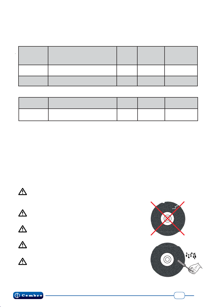
• Do not use the RAIL SAW for purposes other than those intended by Cembre or for
grinding operations using the side surface of the cutting disc as this may break and
cause serious injury. Never use a machine that is faulty, has been tampered with or
which has been modified from its original form.
• Control the surrounding area before operation; the safety distance around the RAIL
SAW for personnel not operating the machine should be at least 15 metres. Hot
sparks which fly off during cutting can cause fire if in the presence of flammable
materials such as dry grass, petrol, wood, etc.
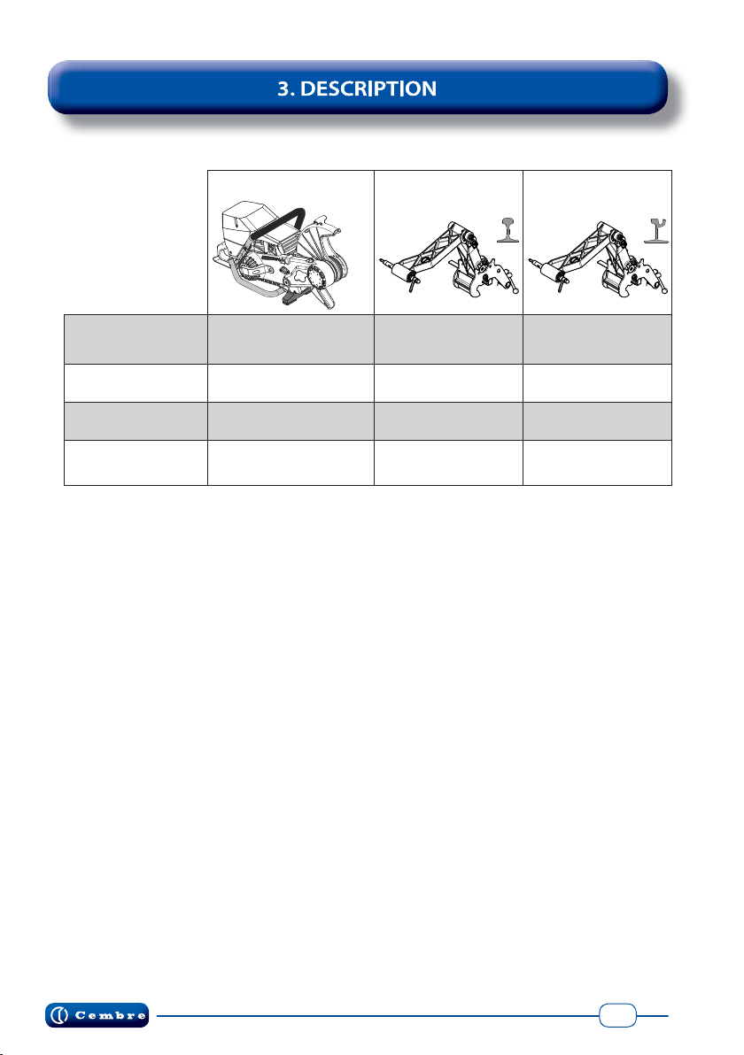
• The RAIL SAW must only be used in conjunction with support arms supplied by Cembre.
• Never operate the RAIL SAW during personal ill health, when tired or under
the effects of alcohol, drugs or medicines which can alter the state of mind
and reduce reaction times; use good judgement in all situations.
• When operating, stand in a stable, secure position and grip the RAIL SAW tightly.
Be sure to work in good lighting conditions or with sufficient artificial lighting.
• Always keep a first aid kit and fire extinguisher on hand in order to intervene promptly
should remove the need arise.
• Avoid inhalation of Petrol fumes and exhaust emissions which contain Carbon Monoxide,
an odourless lethal gas. Ensure good ventilation.
• The fuel and its vapours are extremely flammable.
FIRE AND BURN HAZARD.
• Turn off the engine before refuelling. Dry any spilt fuel.
If the fuel comes into contact with clothing, change the clothing immediately.
Do not start the engine within 3 metres of the refuelling area.
• During transportation, always remove the cutting disc from the RAIL SAW.
Cfllfll h f i i bCbFil b h i

4
Main components (Ref. Fig. 1 page 5):
1
– Air filter spark plug cover
2
– Upper handle
3
– Safety guard (spark guard)
4
– Abrasive cutting disc (to be mounted)
5
– Transmission system side cover
6
– Foot
7
– Nameplate
8
– Support arm pin slot
9
– Silencer / muffler
10
– (EasyStart) Decompression valve
11
– Combustion engine
12
– Abrasive cutting disc fixing
Descriptions and possible configurations:
REFERENCE
RAIL SAW STANDARD
SUPPORT ARM
SUPPORT ARM
FOR GIRDER RAILS
RDS-20P
RDSC-20P * •
SA-RDS •
SAY1-RDS •
RDS-20P-SA
RDSC-20P-SA * ••
13 – Measure for petrol-oil mix
14 – 4mm Allen key for removing side cover
15 – Starter cord grip
16 – Multifunction spanner (torx + cut)
17 – Fuel tank cap
18 – Main ON/OFF switch
19 – Rear control handle
20 – Accelerator
21 – Safety lever
22 – Accelerator block
23 – Air valve control (starter)
* RDSC...type rail saws are provided with a support arm ignition control, it works only
if mounted on the support arm. If the rail saw is not mounted onto the support arm,
an automatic cut-off device stops the engine!

5
FIG. 1
4
3
1
2
8
12
8
21
22
23
5
9
19
6
11
10
16
17
20
18
13
14
15
7

6
3.1) General Characteristics:
RDS-20P RDSC-20P
Application range Rail saw is designed to cut rail with suitable abrasive disc
support arm ignition control NO YES
dimensions refer to Fig. 2 , page 31
weight kg (lbs) 18 (39.6)
Cutting group
n° of revs of drive shaft RPM 4700
drive shaft diameter mm (inch) 25,4 (1) *
max. diameter of cutting disc mm (inch) 406 (16)
max. cutting depth mm (inch) 140
Combustion engine
type Husqvarna, 2 stroke, single-cylinder, air cooled,
electronic start, 5-stage air filter
displacement cm3(cu.inch) 119 (7.26)
bore / stroke mm (inch) 60 mm (2.36) / 42 mm (1.65)
power kW (HP) 5,8 (7.8)
n° of revs idling RPM min. 2700 - max. 9300 ± 150
tank capacity
litres (US Pint)
1,25 (2.65)
carburettor Walbro WG 9
spark plug CHAMPION RCJ6Y, NGK BPMR7A or equivalents
fuel petrol mixture
clutch centrifugal with automatic intervention
start by cord pull with automatic rewind
Acoustic noise (1) dB LpA 105,5 (A) LpCPeak 121,3 (C) LWA 116 (A)
Vibration (2) m/s211,42 max.
* If necessary it is possible to use abrasive discs with a 7/8“(22.2 mm) fixing hole (ref. to § 3.3.1 for details).
(1) Directive 2006/42/EC, annexe 1, point 1.7.4.2 letter u
LpA = weighted continuous acoustic pressure level equivalent.
LpCPeak = maximum value of the weighted acoustic displacement pressure at the work place.
LWA = acoustic power level emitted by the machine.
(2) Directive 2006/42/EC, annexe 1, point 2.2.1.1
Weighted root mean square in frequency of the acceleration the upper limbs are exposed to for each biodynamic
reference axis. Tests carried out in compliance with the indications contained in EN ISOS 5349-1/2 Standard, and
under operating conditions much more severe than those normally found.

7
21
20
22
18
3.2) Safety devices on the machine
ONLY FOR RDSC-20P TYPE: The rail saw must be started only when mounted on the
support arm otherwise the engine will be stopped by a cut-off device.
The safety devices supplied on the RAIL SAW and listed below must be fully functional and
checked before each use. If this is not the case do not use the machine and contact Cembre
for any repairs.
- ON/OFF SWITCH (18) this is found in a very visible
position and is easily operated. It is used for stopping
the machine normally or in emergency.
Ensure you are familiar with how to use the switch
(18) so that you can act promptly in case of emergency.
- ACCELERATOR (20): this is used to run the engine
to full operating speed. It can only be activated by
pressing the interlock lever at the same time (21).
- INTERLOCK LEVER (21): prevents accidental activation of the accelerator which can-
not be activate without pressing this lever.
When the accelerator is released, the abrasive cutting disc continues to turn for
some time. Do not approach the cutting group until the disc has completely stopped.
- ACCELERATOR BLOCK (22): it locks the accelerator in start-up position when
the engine is cold. The accelerator block (22) can only be activated by
pressing the accelerator (20) and the interlock lever (21) at the same time.
Once activated, press the accelerator down.
- SAFETY GUARD (3) designed to protect the
operator from fragments and sparks which fly off
during cutting. Push the handle forwards or
backwards to find the most effective position.
Never use the RAIL SAW without the safety guard
or when the guard is damaged!
start up position
3

8
3.3) Abrasive cutting discs
For maximum performance, use the rail saw in conjunction with the high quality C-Rex range
Cembre discs listed below, in compliance with the requirements of the standard EN 12413 for
bonded abrasives.
Standard discs with 1 “(25.4 mm) mounting hole:
DISC
TYPE
Dimensions
diameter x thickness x hub
mm (inch)
(RPM)
Peripheral
speed
(m/s)
Note
CRDL4381 355x3.8x25.4 (14”x5/32”x1”) 5500 100 standard
CRDL6401 406x4.0x25.4 (16”x5/32”x1”) 4800 100 standard
Available discs with 7/8 “(22.2 mm) mounting hole:
CRDL4387 355x3.8x22.2 (14”x5/32”x7/8”) 5500 100 see § 3.3.1
CRDL6407 406x4.0x22.2 (16”x5/32”x7/8”) 4800 100 see § 3.3.1
– The RPM shown on the abrasive cutting disc label must be equal to or higher than that
produced by the rail saw.
– Never use the rail saw for grinding operations on the side surface of the disc, as it may break
and cause serious injury.
– The cutting discs must only be used for cutting suitable materials.
– During transportation and storage of the rail saw, always remove the cutting disc and lay
it on a flat surface in a dry place protected from frost and moisture.
– Always tighten the fixing screw of the cutting disc with a 20-25 Nm torque, to prevent
the disc from loosening.
– Worn or broken discs must be disposed of in compliance with local statutory requirements.
Always, use good quality cutting discs with a diameter
of 355 mm (14”) or 406 mm (16”) marked “RAIL” specific for
rail cutting.
The cutting disc may only be replaced when the engine
is switched off!
Never use cutting discs designed for a lower rpm than
that of the rail saw.
Never use a cutting disc beyond its expiration date, if
indicated.
Before using a cutting disc always check it is completely
free from damage.
A simple test for verifying the integrity of a cutting disc is to hold
it in the air and gently tap it with a screwdriver or a piece of wood;
an intact disc will produce a low drumming tone.

9
3.3.1) Use of 7/8 “abrasive cutting discs
The rail saw is designed to be used in combination with abrasive discs with a 1 “(25.4 mm)
mounting hole. If necessary it is possible remove the centering ring mounted on the shaft and
use discs with a 7/8 “(22.2 mm) mounting hole.
Removing the centering ring:
- Insert a flat blade screwdriver into the
splitting (1) of the centering ring so as
to extend it and remove the ring from
the hub (2).
- To reassemble it, simply push the ring
on the hub until it stops.
ATTENTION: during the centering ring reassembly, the flanged side must be
turned towards the support plate (D).
D
Remove centering ring from
the hub to use disc with
7/8“(22.2 mm) mounting
hole.
to use disc with 1“(25.4 mm)
mounting hole.
centering ring
already mounted
1
2
1
NO OK
NEVER USE CUTTING DISCS WITH A 1” (25.4 mm) HOLE WITHOUT CENTERING RING
MOUNTED ON THE SHAFT. THIS COULD CAUSE SERIOUS DAMAGE TO THE MACHINE AND
DANGER TO PERSONAL SAFETY.
flanged side
hub

10
4.1) Fuel mixture preparation
Risk of explosion or fire, petrol is extremely flammable, handle with caution.
Risk of intoxication, avoid inhalation of petrol vapours.
Risk of irritation, avoid prolonged and repeated contact with skin.
The rail saw has a 2-stroke air cooled engine which runs on an oil-petrol mix; for the correct
dosage of oil use the measure supplied, according to the following proportions:
1:50 (2 %) of specialist synthetic 2 stroke engine oil (e.g. 5 litres of petrol,
0.1 litres of oil).
Alternatively:
1:33 (3 %) of other 2 stroke engine oils for air cooled engines classified
according to JASO FB/ISO EGB (e.g. 5 litres of petrol, 0.15 litres of oil).
Always use good quality 2 stroke engine oil and a minimum 90 octane Petrol.
Mix petrol and oil together well and prepare only enough for immediate use as the mixture will
age and if several weeks old may cause engine damage.
Always use the correct fuel mixture to avoid:
1 - Smoking engine and dirty spark plug, should the mixture be too oil rich.
2-Excessiveoverheatingwith consequentseizingoftheengine,shouldthemixturebe oildeficient.
4.2) Refuelling
Always refuel with the engine switched off.
Place the rail saw on its side with the tank cap facing upwards.
Using a non-spill fuel container, slowly add the mix, making sure not to spill it;
Always perform refuelling in a well-ventilated area away from the work zone, keeping
a safe distance of at least 3 metres (10 ft).
Use only a non-spill fuel container.
In the event of spillage during topping up, carefully dry the engine before turning it on. Fully
tighten the fuel cap.

11
min. 3 m (10ft)
4.3) Mounting the cutting disc
WARNINGS:
– This operation must be performed with the engine switched off.
– Before using a cutting disc, always verify its compatibility with the rail saw
and observe the rules set out in § 3.4.
– Verify that the hub of the disc is perfectly suitable for the shaft.
– Always mount the disc complete with pressure plate.
– In order to avoid an overtightening of the screw (12), start the engine only when
the abrasive cutting disc is mounted.
– With the 13 mm multifunction spanner supplied, unscrew the locking screws (12) and
retrieve the pressure plate (S).
– Mount the disc on the shaft inside the safety guard so that
it rests on the central stop.
– Mount the pressure plate and lock
all the screws (12) tightening with
a 20-25 Nm.
During the tightening phase
counteract the movement.
of the disc with one hand.
non-spill fuel
container
20-25 Nm
12
12
S

12
The rail saw can be started both on the ground and mounted on the
support arm. We advise that it is started on the ground first to warm
it up, turned off and mounted on the support arm, then re-started.
– Turn the ignition switch to the left into the starting position (Fig. a).
– Press the decompression valve which makes start-up easier (Fig. b).
– Only when the engine is cold: fully pull the air valve control (Fig. c).
Completely press the accelerator, the interlock lever, the accelera-
tor block and then release the accelerator, it will lock in the starting
position (Fig. d).
–Gentlypullthestarter corduntilyoufeelsomeresistance(the starter
hooks will kick in) and then pull vigorously with rapid and decisive
movements until the engine starts (Fig. e).
NOTE:
To avoid damaging the winding device, accompany the starter
cord in the return phase and do not pull it over its stroke.
–
With the engine running, press and immediately release the acce-
lerator to unlock it from the starting position and let it run idle.
– Release the air valve control, if pulled.
– Keep the engine running for a few minutes to warm it up before star-
ting work.
click
ONLY FOR RDSC-20P: Mount the rail saw on to the support
arm before starting the engine. It is not possible to start the engine
on the ground but only when the rail saw is mounted on the arm
otherwise an automatic cut-off device stops the engine!
Always start the machine at a safe distance from the refuelling
area.
Start the engine only when the abrasive cutting disc is mounted.
Before starting, check that the abrasive cutting disc can rotate
freely.
Fig. a
Fig. c
Fig. d
4.4) Starting and stopping the engine
Fig. b
Fig. e

13
Fig. f
To stop the engine
– Release the accelerator and turn the ignition switch to the right into
the STOP position.
• Ground start-up, only for RDS-20P not for RDSC-20P (Fig. f):
To facilitate the starting operation, place one foot on the in
side of the rear handle in order to push the rail saw against
the ground and grasp the upper handle with one hand and.
–
Keep the engine running for a few minutes to warm it up before
starting work.
–
Turn off the engine and mount the rail saw on the support arm.
Wait until the disc has completely stopped before
mounting the machine on the support arm.
– Restart the engine.
112
350
320
210
265
1680
255
The SA-RDS support arm safely supports the rail saw in a comfortable position, which facilitates
fixing and the starting of the engine. The rail saw needs to be guided during manual mode to
obtain a perfectly straight and perpendicular cut. Moreover, the operator can work unhindered
on both sides of the rail to take up the cut easily and precisely. The fixing clamp is designed to
allow a precise and secure tightening of the arm on Vignole type rails.
only for
RDS-20P
- Weight: 8.5 kg (18.7 lbs)
- Dimensions (mm):

14
xxxxxx
2
4
1
3
6
7
Description:
1. Rail saw locking handle
2. Mobile arm
3. Sliding track
4. Clamp locking wheel/release
5. Cutting reference plate
6. Fixed jaw clamp
7. Stationary positioning lever
8. Knob to adjust arm height
9. Vertical arm
10. Mobile jaw clamp
11. Rail saw locking pin
9
5
11
10
8
7
serial number

15
5.1) Attaching the support arm to the rail top
Open mobile jaw (6) by turning handwheel (7).
Rest the fixing clamp on top of the rail head so that all four support teeth (Ref. Fig. a) touch the
rail. Tighten the fixing clamp firmly with handwheel (Ref. Fig. b).
Before mounting the rail saw on the arm,
check that the clamp is positioned and locked
in a correct manner on the rail head (Ref. Fig. b).
Ifthearmiswronglypositioned,itcancausecut-
ting which is not perfectly straight (Ref. Fig. c, d).
NOTE: The fixing clamp of the SA-RDS support arm is designed to allow a precise and secure
tightening of the arm on Vignole type rails; for fixing the rail saw on most Girder type rails the
SAY1-RDS support arm is available.
For fixing the rail saw on other different rail types, please contact Cembre.
Vignole
type rail other different rail types, contact Cembre
OK
NO
NO
Fig. b
Fig. c
Fig. a
Fig. d
4 support
teeth 7
6
fixing clamp
Girder
type rail

16
5.2) Adjusting the height of the support arm
The SA-RDS support arm can be adjusted to
meet the cutting requirements based on the rail
dimensions and to allow the operator to adopt
a comfortable working position according to his
height.
There are 3 positions available; normally the
most suitable position is the one with knobs (8)
positioned centrally; to choose another position,
extract knobs (8) and move them into the upper
or lower slot.
Align knobs (8) in the same position to
avoid a cut which is not perfectly straight and
perpendicular to the rail.
2
1
2
2
2
1
1
8
8
The SA-RDS manual support arm can be
overturned from one side to the other
without needing to be removed from the
rail, to allow a comfortable and precise re-
sumption of cutting.
To carry out this operation, it is sufficient
to grasp it at point (A), rotate it by 180°
and move it so that it rests
on the opposite side; the re-
ference (8) has to rest on the
clamp (6).
Before mounting the
rail saw on the arm, check
that lever (7) is correctly
inserted.
8
6
A
7
5.3) Overturning the SA-RDS support arm
Overturning the arm must be carried out without the rail saw.
WARNING - Hand crushing hazard

17
1
2
1- Mount the rail saw on the support arm,
match the interface pin (11) with the slot of
the rail saw.
2- Push and rotate handle (1) tightening it fully.
To dismount the rail saw, completely loosen handle
(1) and remove it.
5.4) Mounting/dismounting the rail saw on the support arm
Before mounting the rail saw on the support arm, make sure that:
- the clamp (6) is firmly locked as described in § 5.1,
- the lever (7) is completely inserted
- the two knobs (8) are aligned at the same height.
ONLY FOR RDSC-20P:
The engine will be stopped by a cut-off device if the rail saw is
not mounted on the support arm (Ref. to § 3.2).
The figure shows the correct positioning of the rail saw on the support arm on both sides of the rail.
7
6
1
11 8

18
Cutting line
The reference plate (5) is essential for exactly
locating the cutting line on the rail.
The length of the plate depends on the
machine-support arm assembly.
On the first cut it is necessary to establish
anoriginofthecuttingdistancesbyremoving
excess plate:
– Fully rotate the plate (5) to 90°.
– Cut the rail (Ref. to § 7), the excess part of
the plate will be cut.
Forsubsequent,it will be possibletodefine
the exact point at which the disc will touch
the rail and, therefore, to position the arm
at anappropriatedistance,using the plate.
When not in use, or during transpor-
tation of the arm turn the plate (5) inwards
to prevent its bending or damage.
5
open position
closed position

19
WARNINGS:
- Always consult your employer’s rules and procedures to cut rails in the presence of electri-
cal traction return current.
- Follow the precautions described in § 7.1.
- Ensure that everyone keeps the safety distance from the cutting zone.
- Remove aggregate (min. 15 cm) from the cutting area under the rail, to avoid
interference with the cutting disc guard and to make it easier to remove the disc when the
cut is finished.
– Fix the arm to the rail at the pre-esta-
blished point (Ref. to § 5.1)
NOTE: Check that the reference plate (5) is
totally turned; during the first cut, the
origins of the cutting distances must be
defined exactly (Refer to § 6).
– Mount the rail saw onto the arm (Ref.
to § 5.4).
– Start the engine (Ref. to § 4.4).
– Support the rail saw by holding the upper
handle with one hand and with the other
hand pull out lever (7) locking it in the
external position to release the arm.
– Press the accelerator completely, slowly
bring the cutting disc towards the rail,
whilst respecting the precautions descri-
bed in § 7.1.
7
5

20
NOTE: Some factors such as the diameter of the cutting disc, a partially worn disc and the rail
dimensions, can influence the cutting operation and prevent the execution of a full cut. In such
a case, the arm will have to be overturned (Ref. to § 8.3) and the process completed by taking
up the cut on the opposite side.
– Start the cut by using regular alter-
nate movements, maintaining a steady
pressure during the whole cutting phase.
Thedouble articulationof thesupport arm
will relieve the operator of the weight of
the machine thus making the cutting
operation easier.
– Once the operation is finished, release the accelerator, lift the
rail saw and re-lock the arm in its resting position by pushing
in the lever (7) fully .
– Switch off the engine by using the switch (18) and wait for the
disc to completely stop turning before carrying out any further
interventions.
min. 15 cm
Taking up
procedure
18
aggregate
This manual suits for next models
5
Table of contents
Other Cembre Saw manuals
Popular Saw manuals by other brands

Optimum
Optimum OPTIsaw S 131GH operating manual

Meec tools
Meec tools 024232 operating instructions

Bomar
Bomar Workline 410.280 DG operating instructions

Meister
Meister TS800M Translation of the original instructions

skilsaw
skilsaw SPT64MTA Operating/safety instructions

Craftsman
Craftsman RADIAL ARM SAW 315.22038 owner's manual