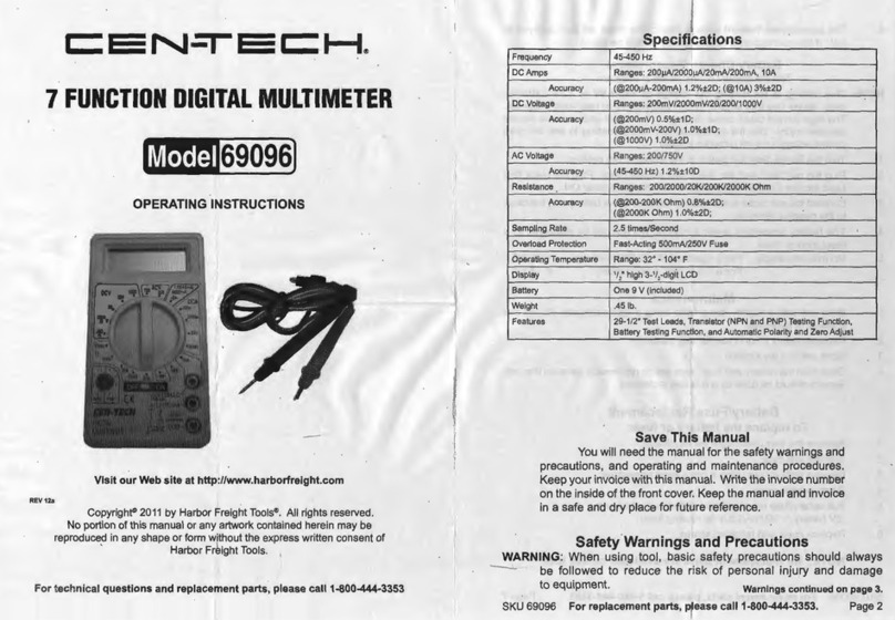
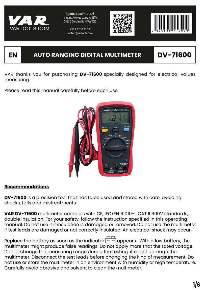
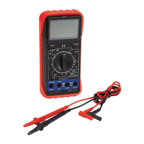
Centech 32418 User manual

18 RANGE ANALOG MUL18 RANGE ANALOG MUL
18 RANGE ANALOG MULTITESTERTITESTER
TITESTERTITESTER
TITESTER
OPERATING INSTRUCTIONS
3491 Mission Oaks Blvd., Camarillo, CA 93011
Visit ourWeb site at http://www.harborfreight.com
Copyright©2005byHarborFreightTools®. Allrightsreserved.Noportion
of this manual or any artwork contained herein may be reproduced in any
shape or form without the express written consent of Harbor FreightTools.
For technical questions and replacement parts, please call 1-800-444-3353
®
32418
WARNING!
Electric shock can cause DEATH or SEVERE PERSONAL INJURY.
Nevertouchexposed conductors ofelectricity with
fingers,hands or anyotherbody part.

SKU32418 Page2For technical questions, please call 1-800-444-3353.
Specifications
SaveThis Manual
Youwillneedthemanualforthesafetywarningsandprecautions,andoperating
and maintenance procedures.Keep your invoice with this manual. Write the invoice
numberontheinside ofthefront cover.Keepthemanualandinvoicein asafeand dry
placefor futurereference.
noitcnuFycaruccA/egnaR
segnaRegatloVCA*DSF%5±V0001/005/052/05/01
segnaRegatloVCDDSF%5±V0001/005/052/05/01/52.0
segnaRegarepmACD )Vm004<:porDegatloV(DSF%5±Am005/52/5.2/52.0
segnaRecnatsiseR K/01x/1x Ωcrafo%5±
serutaeFrehtO oreZ,tseTrotsisnarT,tseTytiunitnoC,tseTyrettaBV5.1 oreZdna,tsujdA ΩtsujdA
noitcelfeDelacS-lluF="DSF"*
METINOITPIRCSED
noitcetorPdaolrevOedoiddnaesufA5.0
ycneuqerFzH06
yalpsiDtnemevomlacinahcemortcele,golanA
yrettaBseirettaB"AA"owT
erutarepmeTgnitarepOF°401ot°23
ytidimuHgnitarepOHR%58nahtsseL
erutarepmeTegarotSF°221ot°41
thgieWsbl7.0
seirosseccA(deR +(kcalBdna) -sdaeLtseT"53)

SKU32418 Page3For technical questions, please call 1-800-444-3353.
SafetyWarnings and Precautions
WARNING:When using tool, basic safety precautions should always be followed to
reducetherisk of personalinjury and damage toequipment.
Read all instructions before using this tester!
If all warnings and safety precautions in this manual are not followed
completely,the protection provided by this product will be reduced.
On this sheet, and in the included manual:
WARNING indicates a potentially hazardous situation which, if not avoided,
could result in death orserious personal injury.
CAUTION indicates a potentially hazardous situation which, if not avoided,
may result in a minor/moderate personal injury or damage to this tool or the unit
being tested by it. WARNING
1. Avoid working alone. If an accident happens, an assistant can bring help.
2. Keep work area clean. Clutteredareas inviteinjuries.
3. Avoid electrical shock.Use extremecautionwhenworking arounduninsulated
conductors or bus bars. Prevent body contact with grounded surfaces such as
pipes,radiators, ranges, andcabinet enclosureswhentesting voltages.
4. Avoid damaging meter.Use only as specified in this manual.
5. Observe work area conditions. Do not test circuits in damp or wet locations.
Don’t expose to rain.Keep work area well lit.
6. Keep children away. Children mustnever beallowedin theworkarea. Donot
let them handle machines, tools, or extensions cords.
7. Store idle equipment. When not in use, tools must be stored in a dry location
to inhibit rust. Always lock up tools and keep out of reach of children.
8. Dress properly. Donotwearjewelry asan accidentalbrush may causea short
circuit causing electric shock or severe burns. Protective, electrically noncon-
ductive clothes and nonskid rubber-soled footwear are recommended when
working.Wear restrictivehair covering tocontain long hair.
9. Use eye protection. Alwayswear ANSIapprovedimpact safetygoggles.
10. Do not overreach. Keep proper footing and balance at all times.Do not reach
over or across electrical cables or frames.
11. Maintain tools with care. Ensure multimeter has a fresh battery.Inspect tool
cordsperiodically and,ifdamaged, havethemrepaired byanauthorizedtechni-
cian.
12. Stay alert. Watch what you are doing, use common sense.Do not operate any
toolwhenyou are tired.

SKU32418 Page4For technical questions, please call 1-800-444-3353.
13. Check for damaged parts. Before using any tool, any part that appears dam-
aged should be carefully checked to determine that it will operate properly and
performits intendedfunction.Checkforalignmentand bindingof movingparts;
any broken parts or mounting fixtures; and any other condition that may affect
proper operation. In addition to a general inspection, look specifically for:
a. Pay special attention to the insulation protecting the connectors.
b. Check the leads for exposed metal,damaged insulation,and continuity.
Replace damaged test leads immediately, before use.
Any part thatis damagedshould beproperly repairedor replacedbya qualified
technician.Do not use the tool if any switch does not operate properly.
14. Remove the test leads before performing maintenance, opening the case,
or the battery compartment.
15. Do not use the multimeter if:
a. The test leads are damaged in any way.
b. The battery is low.
c. Near any explosive gasses or fumes.
d. Any abnormal operation is detected.
(If in doubt about the condition of the meter, have it serviced.)
e. The battery cover is open.
16. This meter should be powered only by two, correctly installed 1.5V“AA”
typebatteries.
17. Accessories. Only use accessories intended for use with this tool. Approved
accessories areavailablefrom HarborFreightTools.
18. Donot operate tool ifundertheinfluence of alcohol ordrugs. Readwarning
labels on prescriptions to determine if your judgment or reflexes are impaired
while taking drugs. If there is any doubt, do not operate the tool.
19. People with pacemakers should consult their physician(s) before using
this product. Electromagnetic fields in close proximity to a heart pacemaker
could cause interference to or failure of the pacemaker.
In addition, caution is necessary when near the coil, spark plug cables, or
distributor of a running engine. The engine should always be off if adjust-
ments are to be made to the distributor.
20. Do not test voltage on circuits higher than 1,000 volts. Do not test current
on DC circuits higher than .5 amps or on AC circuits at all.
Warning:Thewarnings,cautions,andinstructionsdiscussedinthisinstructionmanual
cannot cover all possible conditions and situations that may occur. It must be
understood by the operator that common sense and caution are factors which
cannot be built into this product, but must be supplied by the operator.

SKU32418 Page5For technical questions, please call 1-800-444-3353.
Unpacking
Whenunpacking,makesure thattheAnalog MultimeterandbothTest Leads
are included.If any parts are missing or broken, please call Harbor Freight Tools at
the number on the cover of this manual.
CAUTION
1. Priortotesting capacitors,resistance,diodes,or continuity;disconnectall power
to the circuit and discharge all high-voltage capacitors.
2. Check fuse before testing current.
3. Use the proper settings, terminals, techniques, and range for the tests per-
formed. Always start with the range stated in the instructions.
4. Be careful not to apply voltage to theTest Leads when the meter is in an ohms
testing position. Damage can occur to the multimeter.
NOTE:
The batteries must be
installed before first use.
See
Battery Replacement
under
Maintenance
, page 11.

SKU32418 Page6For technical questions, please call 1-800-444-3353.
Control and Scale Layout
Refer to this diagram while following the directions in the
Operation
section.
The bold numbers inside brackets [XX] below refer to the page number where the
explanation of the function starts.
-COM Jack + Jack
Transistor
Selection
Area [9]
DC Current
Selection
Area (mA)
[8]
Ohm
Selection
Area (Ω) [8]
AC Volt
Selection
Area [8]
Ohm Zero
Adjust [8]
DC Volt
Selection
Area [7]
Continuity
Selection
Area [9]
Battery
Selection
Area [10]
Ohm Scale
[8]
Current
Gain Scale
(hFE) [9]Battery
Test Scale
[10]
Accuracy
Mirror [6]
Leakage
Current
(lceo) Scale
[9]
Amperage/
Voltage
Scales [7]
Continuity
Indicator [9]
The Accuracy Mirror
The Accuracy Mirror is used to insure that the meter’s pointer is being read
straight,ensuring accuracy. Simply makesure thatthe meteris angledso that,when
reading it, the reflection of the pointer is hidden under the pointer.
Zero Adjust
[10]

SKU32418 Page7For technical questions, please call 1-800-444-3353.
WARNING!
Electric shock can cause DEATH or SEVERE PERSONAL INJURY.
Always observe the following precautions when working:
1. Never touch exposed conductors of electricity with fingers, hands or any
other body part.
2. Use caution when working near voltages above 30VAC rms, 42VAC peak,
or 60VDC. Voltages this high present a risk of electric shock.
3. Disconnectthecircuit’spower beforeconnecting the meter inseries,when
measuring current.
4. Connect the common (COM) test lead first and disconnect it last.
5. Hold the probes with fingers behind guards.
Operation
DC Voltage Measurements
Measure DC voltages up to 1,000V.
1. TurntheRange SelectorSwitch to1000 DCV.
Alwaysstart withthehighestrange
if the voltage is unknown.
2. Plug the red lead into the +Jack.
Plug the black lead into the -Com
Jack.
3. Carefully touch the appropriate ex-
posedconductorswiththetips ofthe
probes to measure the voltage (not
amperes).
4. Readmeasurementonthe Volt/Amp
Scale - see
How to Read the Volt/
Amp Scale
table, right.
If the needle moves in the opposite
direction, then the probes are con-
nected incorrectly. Reverse the
probes’locations.
If the voltage is less than 500 volts,
setthe RangeSelectorSwitch tothe
next lower range until the meter
pointer is mid-range on the scale.
elacSpmA/tloVehtdaeRotwoH
egnaRpmA/tloV elacSpmA/tloV daeRebot reilpitluMtluseR
000101-0001
00505-001
052052-0–
0505-0–
52052-01.0
01
(rof CD ylno)
01-0–
01
(rof CA ylno)
deR elacS01-0 –
5.2052-010.0
52.0052-0100.0
:trahCehtesUoT (tfelehtniegnardetcelesehtdniF.1 egnaR .nmuloc)
(retnecehtnidetacidnielacsehtdaeR.2 elacS )
.wortahtfonmuloc thgirehtnireilpitlumehtybgnidaerehtylpitluM.3 (reilpitluM "afI.wortahtfonmuloc)–ninwohssi" eriuqertonseodgnidaerehtneht,nmulocthgireht .noitacilpitlum
:elpmaxE ottessiegnarehtfI AmCD52 ehtneht, 052-0 elacs
ybdeipitlumdnadaerebdluow 10.0 .
(tnemerusaeM=reilpitluMXgnidaeR )
fognidaerarof,oS 011 dluowtnemerusaemeht,egnarsihtni
eb AmCD1.1 (1.1=10.0X011 .)

SKU32418 Page8For technical questions, please call 1-800-444-3353.
5. Whentesting iscomplete,removeTest Leadsand storethemand themeter ina
safe, dry location.
AC Voltage Measurements
Measure AC voltages up to 1,000V.
1. Turn theRangeSelectorSwitchto 1000 ACV.
Always start with the highest range if the voltage is unknown.
2. Follow the directions on the previous page under
DC Voltage Measurements
(except for the polarity directions, they are unnecessary with AC).
DC Current Measurements
Measure DC conductors carrying up to 500 mA (.5 A).
1. Turn the Range Selector Switch to the 500 DCmA position. Plug the red lead
into the +Jack. Plug the black lead into the -Com Jack.
Note: Testing current should ONLY be done in series, with the circuit con-
nected and current flowing.
3. Carefully connect the test leads to the circuit or the load being tested.
4. If the Amperage is less than 25 mA (.025 A), set the Range Selector Switch to
the next lower range until the meter pointer is mid-range on the scale.
5. Whentesting iscomplete,removeTest Leadsand storethemand themeter ina
safe, dry location.
Resistance (Ohm) Measurements
Circuit resistance can be measured on ranges from meter reading times 1 to meter
readingtimes 1,000.
Note: Testing resistance should ONLY be done with the power to the circuit
disconnected. Test to make sure no voltage is present first. If voltage is
appliedwhiletesting,disconnect the testerimmediately,otherwise thefuse
may blow and the tester may be damaged-see
Fuse Replacement
under
Maintenance,
page11.
1. Turn the Range Selector Switch to the Ohm testing position (between x1ΩΩ
ΩΩ
Ωand
KΩΩ
ΩΩ
Ω) you will be measuring at.
2. Plug the red lead into the +Jack. Plug the black lead into the -Com Jack.
3. Short theTest Leads together. The meter should read“0”Ohms.
4. If the meter does not read “0” Ohms, the ohmmeter needs to be calibrated to
enableaccuratemeasurements.
a. Withthe testleadsheld together,adjustthe Ohm Zero Adjust Knobuntilthe
meter’spointeraligns on“0”.
b. Ifthe pointercan’t alignwithzero, thebatteries may needto bereplaced-see
BatteryReplacement
under
Maintenance
,page 10.

SKU32418 Page9For technical questions, please call 1-800-444-3353.
5. Touch the exposed conductors with the tips of theTest Leads. If, by chance, a
voltage is present, the fuse may blow-see
Fuse Replacement
under
Mainte-
nance,
page 11. Immediately remove theTest Leads from the conductors.
6. Read the Ohm Scale. If in the x1ΩΩ
ΩΩ
Ωsetting, the measurement is as read. If in
the x10ΩΩ
ΩΩ
Ωsetting, multiply the reading by 10. If in the xKΩΩ
ΩΩ
Ωsetting, multiply the
readingby 1,000.
If the resistance measured is off the scale, move the Range Selector Switch to
ahigher Ohms position.
7. ContinuityTesting: Turn the Range Selector Switch to the Continuity (x1Ω)Ω)
Ω)Ω)
Ω)
setting. This test is a type of Ohms test. When the wiring between the test
leads haslow resistance, the Continuity Indicator will illuminate. This isuseful
for detecting breaks in wiring.
8. When testing is complete, switch the meter to a DCV testing location (to
help prolong battery life), remove the Test Leads, and store the leads and
meter in a safe, dry location.
Transistor Measurements
Caution:This tester is capable of damaging or destroying a transistor.It is entirely
the responsibility of the user to ensure that the settings are correct for the
specific transistor before connecting the meter.Harbor Freight Tools takes no
responsibility for any damage, whether direct or consequential that may be
done to the device under test due to improper use or connection.
1. Turn the Range Selector Switch to the hFE (x10Ω)Ω)
Ω)Ω)
Ω) position and set the “0”
Ohms as stated above.
2. To check the Iceo (leak) value:
a. Plug the red lead into the +Jack. Plug the black lead into the -Com Jack.
b. Carefully connect the black test lead to the emitter and the red test lead to
the collector of the transistor being tested.
c. Read the Iceo value on the Iceo scale.
3. To check the hFE value:
a. If connecting to a PNP transistor:
Plugtheblack lead intothe-Com Jack andconnect theother endof the
leadtotheEmitter. ConnectthehFEConnector (anoptionalaccessory,
see page 12) to the +Jack. Carefully connect its red clip to the Collec-
tor and its black clip to the Base.
If connecting to a NPN transistor:
Plug the red lead into the +Jack and connect the other end of the lead
totheEmitter. Connectthe hFEConnector (anoptional accessory, see
page 12) to the -Com Jack. Carefully connect its red clip to the Collec-
tor and its black clip to the Base.
b. The meter will show the approximate hFE (IC/IB) value on the hFE scale.

SKU32418 Page10For technical questions, please call 1-800-444-3353.
Maintenance
1. Wipe unit with a damp cloth using a light detergent. Do not use solvents or
abrasives. Allow the unit to dry completely before use or storage.
2. Remove batteries if not in use for long periods.
4. Store unit in a dry location out of children’s reach.
5. Aside from the fuse and batteries, there are no user replaceable parts on this
unit.REPAIRS SHOULD BE DONE ONLY BY A QUALIFIEDTECHNICIAN.
6. Meter Pointer Calibration
Over time, it may become necessary to adjust the meter pointer to align on “0.”
a. Remove the Test Leads from the multimeter and make sure that the unit is
not set at an Ohm testing setting.
b. Using a smallstandard screwdriver, placeit onthe smallmeterZero Adjust
screw right below the center of the dial. See
Control and Scale Layout
on
page6.
c. Turn screwslightly untilthe pointer pointsdirectly at the zeroon the Amper-
age/Voltage Scale.Figure A
Screw
4. When testing is complete, switch the meter to a DCV testing location (to
help prolong battery life), remove the Test Leads, and store the leads and
meter in a safe, dry location.
BatteryTesting
1. Turn the Range Selector Switch to the 1.5V (“AAA”, “AA”, “C”, & ”D” Size Bat-
tery) setting.
2. Plug the red lead into the +Jack. Plug the black lead into the -Com Jack.
3. Connectthered testleadto thepositive endof thebatteryandtheblack lead to
thenegative.
4. Read measurement. When testing is complete, removeTest Leads and store
them and the meter in a safe, dry location.
7. Battery Replacement
If the Ohms cannot be adjusted to
indicatezero, thebatteriesrequire
replacement.
a. Remove theTest Leads from the
multimeter.
b. Turntheunitovertoshowitsback.
c. Remove the screw indicated in
Figure A
using a cross-head
screwdriver.

SKU32418 Page11For technical questions, please call 1-800-444-3353.
d. Open the back cover.
e. Removethebatteriesandreplace
them,being suretoalign thenew
batteries properly. See
FigureB
.
f. Put the back cover on, bottom
edge first. See
Figure C
. Then,
retightenthe screw.
Figure C
Figure B
Fuse
spare
fuse
holder
“AA” Batteries
8. Fuse Replacement
Ifthe multimeteris exposedto excessivecurrent, misused,or dropped,the fusemay
become blown. Check the fuse if the meter does not work for no apparent reason.
a. Followdirections
a
through
d
un-
der
Battery Replacement
to
remove the back cover.
b. Notethelocationofthesparefuse
holder and the fuse in
Figure B
.
Note: A spare fuse is not in-
cluded.
c. Carefullyexamine thefuse inthe
meter. If the thin wire in the tube
is broken, the fuse is blown and
needs to be replaced. See
Fig-
ureD
.
Warning: ONLY replace the fuse
in this meter with another fast-
acting 0.5A fuse. Using the
wrong fuse or using another
material or object instead of a
fuse is very dangerous and
may cause a fire.
d. Afterreplacingthefuse, closethe
meter. Putthebackcoveron,bot-
tom edge first. See
Figure C
.
Then,retighten thescrew.
Figure D
Fuse

SKU32418 Page12For technical questions, please call 1-800-444-3353.
PLEASE READ THE FOLLOWING CAREFULLY
THE MANUFACTURER AND/OR DISTRIBUTOR HAS PROVIDEDTHE
WIRINGDIAGRAM INTHISMANUALASAREFERENCETOOLONLY. NEITHER
THEMANUFACTURER OR DISTRIBUTORMAKESANYREPRESENTATIONOR
WARRANTYOFANY KINDTOTHEBUYERTHAT HE OR SHEIS QUALIFIEDTO
MAKE ANY REPAIRSTOTHE PRODUCT,ORTHAT HE OR SHE IS QUALIFIED
TO REPLACEANY PARTSOFTHEPRODUCT. IN FACT,THE MANUFACTURER
AND/ORDISTRIBUTOREXPRESSLY STATESTHATALLREPAIRS ANDPARTS
REPLACEMENTS SHOULD BE UNDERTAKEN BY CERTIFIEDAND LICENSED
TECHNICIANS,AND NOT BYTHE BUYER. THE BUYER ASSUMES ALL RISK
AND LIABILITY ARISING OUT OF HIS OR HER REPAIRSTOTHE ORIGINAL
PRODUCT OR REPLACEMENT PARTSTHERETO, OR ARISING OUT OF HIS
OR HER INSTALLATION OF REPLACEMENT PARTSTHERETO.
Wiring Diagram
Aside from the fuse and batteries, there are no
user replaceable parts on this unit.
Note: The hFE connector is available as an optional accessory.
It can be ordered using part Sku 28532.
Table of contents
Other Centech Multimeter manuals

Centech
Centech 69096 User manual

Centech
Centech 37772 User manual

Centech
Centech 98025 Installation manual

Centech
Centech 95342 Parts list manual

Centech
Centech 37772 User manual

Centech
Centech 42396 User manual

Centech
Centech 90939 User manual

Centech
Centech 90926 User manual

Centech
Centech 37772 Original instruction manual

Centech
Centech 98025 Installation manual