PEAKMETER PM5205 User manual

I
Contents
Safety Information................................................................................................................................................ 1
Warning...............................................................................................................................................................................................1
Warranty..............................................................................................................................................................................................1
Accessories......................................................................................................................................................................................... 2
Introduction........................................................................................................................................................... 2
Front Panel..........................................................................................................................................................................................2
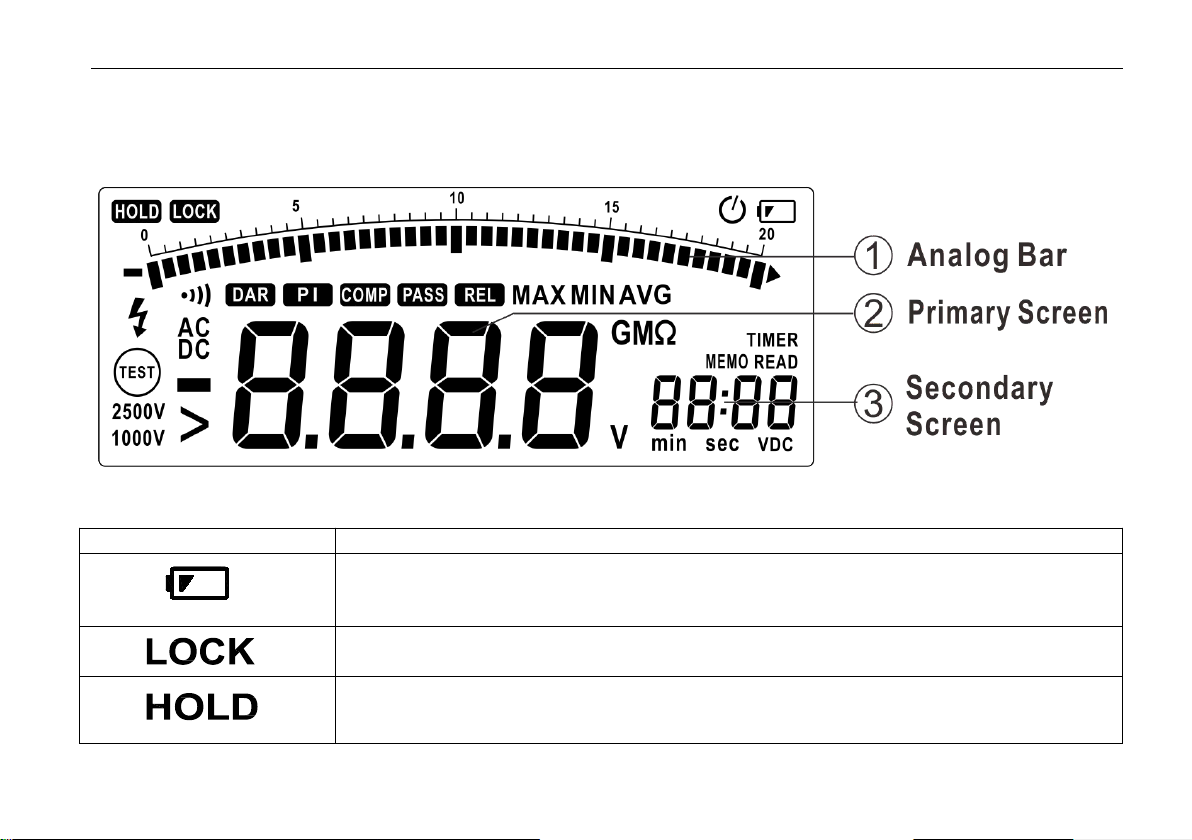
Display Screen....................................................................................................................................................................................3
Display Messages............................................................................................................................................................................... 5
Buttons................................................................................................................................................................................................7
Rotary switch......................................................................................................................................................................................9
Input Terminal.....................................................................................................................................................................................9
Function Description.............................................................................................................................................9
Power-Up Options.............................................................................................................................................................................. 9
Automatic Power Off........................................................................................................................................................................10
Hold Funcion.................................................................................................................................................................................... 10
Relative Measurement...................................................................................................................................................................... 10
Insulation Test Lock..........................................................................................................................................................................11
Storing Test Data.............................................................................................................................................................................. 11
Reading Test Data.............................................................................................................................................................................12
Delete Data....................................................................................................................................................................................... 13
Compare Function............................................................................................................................................................................ 14
Timer Function................................................................................................................................................................................. 16
MAX/ MIN/AVG..............................................................................................................................................................................18
DAR & PI......................................................................................................................................................................................... 19
Making Basic Measurements............................................................................................................................. 19
Measuring DC Voltage..................................................................................................................................................................... 19
Measuring AC Voltage...................................................................................................................................................................20

II
Measuring Resistance.......................................................................................................................................................................21
Insulation Test...................................................................................................................................................................................22
Replacing battery................................................................................................................................................ 23
Specifications....................................................................................................................................................... 24
Accuracy........................................................................................................................................................................................... 26

Insulation Tester
1
Safety Information
This style of digital multimeter is designed and manufactured according to the safety requirements set out by the
IEC61010-1 standards for electronic test instruments . Its design and manufacture is strictly based on the provisions in the
1000V CAT Ⅲ of IEC61010-1 and the Stipulation of 2-Pollution Grade.
Warning
To avoid possible electric shock or personal injury, follow these guidelines:
Use the Meter only as specified in this manual or the protection provided by the Meter might be impaired.
Do not use the Meter or test leads if they appear damaged, or if the Meter is not operating properly. If in doubt, have
the Meter serviced.
Always use the proper terminal, switch position, and range for measurements before connecting Meter to circuit
under test.
Verify the Meter’s operation by measuring a known voltage.
Do not apply more than the rated voltage as marked on the Meter, between the terminals or between any terminal and
earth ground.
Use caution with voltages above 30 V ac rms, 42 V ac peak, or 60 V dc. These voltages pose a shock hazard.
Replace the battery as soon as the low battery indicator ( ) appears.
Disconnect circuit power and discharge all high-voltage capacitors before testing resistance, continuity, diodes, or
capacitance.
Do not use the Meter around explosive gas or vapor.
When using the test leads, keep your fingers behind the finger guards.
Remove test leads from the Meter before opening the Meter case or battery door.
Never operate the Meter with the cover removed or the battery door open.
Comply with local and national safety requirements when working in hazardous locations.
Use proper protective equipment, as required by local or national authorities when working in hazardous areas.
Use only the replacement fuse specified or the protection may be impaired.
Warranty
The meter is warranted to be free from defects in material and workmanship under normal use and service. The

2
warranty period is one year and begins on the date of shipment. Parts, product repairs, and services are warranted for 12
months except for misused, altered, neglected, contaminated, or damaged by accident or abnormal conditions of operation
or handling.This warranty does not apply to fuses, disposable batteries.
Accessories
Item
Test Leads
Clips
Battery AA LR6
Manual
Quantity
2
2
8
1
Introduction
Front Panel

Insulation Tester
3
Display Screen
Indicator
Description
Low battery Indicates when it is time to replace the battery.
To avoid false readings, which could lead to possible electric shock or personal injury,
replace the battery as soon as the low battery indicator appears.
Indicates a test lock will be applied the next time you press Test Button on the meter,the
test lock acts to hold down the button until you press Test Button again.
Hold function ,the meter do not update display.

Accessories
4
Indicator
Description
Compare function is selected
When compare function is selected,when the measuring value between upper limited value
and lower limited value ,display this sign.
Compare function is selected
In insulation test mode, display the DAR value
In insulation test mode, display the PI value
Timer function is selected
Store function is selected
View the memory data,when the data is invalid,display---
DC Voltage function is selected
AC Voltage function is selected
In insulation test mode ,test voltage unit
Minus, When the measure value lower than 0,display the sign.
Greater symbols,In insulation test mode, indicates the measure value overflow.
Unsafe voltage warning,In insulation mode,indicates greater 20V voltage is detected on
the input terminals.

Insulation Tester
5
Indicator
Description
Continuity test function is selected
Auto power off function is selected
Insulation test Indicator.when the rotary switch at insulation position, this sign
appers,when the test voltage is present ,the sign alternate on or off
Source voltage rating for insulation test
Timer unit
Measure unit
Display the Max,Min Avg value
Display Messages
Indicator
Description
batt
Appears on primary display Indicates the battery too low for reliable operation,please
replace battery.
bat
Appears on Auxiliary display,Indicates the battery too low to perform Insulation test
P r E S
Preset value
POFF
Auto power off function is disabled

Display Messages
6
Indicator
Description
LIVE
In insulation mode,indicates meter have detected the voltage on the input terminals
DISC
In insulation mode,indicates the meter performs the auto discharge function.;not to touch
any input terminals in this mode.
SAVE
Store measuring data
dEL n:
Delete the selected data
dEL ALL
Delete all memorized data
COMP Hi
The upper limited value
COMP Lo
The lower limited value
- - - - COMP
The limited value is invalid
Beep function is disabled

Insulation Tester
7
Buttons

8
Buttons
Description
○
1
Active store function: store the measureing data to memory
○
2
Active read function,to view the data store in memory; change cursor position.
○
3
1:in dcv ,acv,continuty mode to view the max value,min value ,avg value, upper limited value,
lower limited value,relative value
2:in insulation mode to view max value,min value ,avg value, upper limited value, lower limited
value,preset timer,DAR,PI
○
4
Confirm Button
○
5
Back Light on/Off,when the light turn on ,after 10s the meter auto turn off light
○
6
Active the timer function
○
7
Active hold function(in DCV,ACV,Continuity) or lock function(Insulation)
○
8
Active rel function(in dcv,acv,continuity mode);change cursour position ;
○
9
Active compare function
○
10
Select one test output voltage for insulation test.
○
11
Active insulation test

Insulation Tester
9
Rotary switch
Position
Function
OFF
Turn off the meter power
V
DC Voltage :0.1V~1000V
V
AC Voltage 0.1V~750V
Ohm and continuity :0.01Ω~200.0Ω
Insulation
Insulation Test 0.01MΩ~100.0GΩ,Test output Voltage 250V(default)、500V、1000V、2500V,
the test output volatage have selected will be saved .
Input Terminal
Terminal
Description
HI VΩ
Input /output positive terminal
COM
Common terminal except Inuslation measure
LO
Common terminal in Inuslation measure
Function Description
Power-Up Options
Holding a button down while turning the Meter on activates a power-up option. Power-up options allow you to use
additional features and functions of the Meter. To select a power-up option, hold down the appropriate button indicated
while turning the Meter from OFF to any switch position. Power-up options are cancelled when the Meter is turned Off
Buttons
Function
SELECT
Disables automatic power-off function Display shows PoFF until the button is released
ENTER
Disable Beep function

Buttons
10
Automatic Power Off
The Meter have automatic power off function(Sleep mode)to conserve battery power .if there is no function change or
button press for 10 minutes. The Meter comes out of Sleep mode when a key is pressed or when the rotary switched is
changed.
To disable the Sleep mode, hold down SELECT button while turning the Meter on. Sleep mode is always disabled in the
insulation test mode, or if the auto power off feature has been disabled by pressing SELECT button when the Meter is
turned on.
Hold Funcion
Press Hold button to freeze the displayed value. Press again to release the display.
Relative Measurement
Show the difference between actual value and the relative base.
Press REL Button to enter relative measurement and the meter will record the initial value when pressing the key.
Displayed value = Actual value -Initial value
Press REL Button again to exit relative measurement.
Press SELECT button to view Initial value,when the Initial value is invalid,display ----.

Insulation Tester
11
Insulation Test Lock
In insulation test mode, press Test button to perform insulation test until the button is released.when the button is
released,the screen display hold sign.
Press Lock Button ,then the screen display Lock sign,press Test Button ,the meter will perform insulation test unitl you
press Test button again;The test lock will unlocked while to cancel insulation test.
Lock function is invalid when timer function is selected.
Storing Test Data
Press MEMO button, the meter enter Hold status automatically. LCD screen display ‘MEMO’ and the memory code
on secondary display (see below). Press △/▽button to change the code, press enter to save the data in the preferred
memory code and the screen display ‘SAVE’.The data is stroed successfully when the buzz beeps.The meter can save 20
datas and memory code from 00 to 19.

Automatic Power Off
12
Reading Test Data
Press READ button to display the data in memory. Press △/▽button to change the code and read the data
accordingly.

Insulation Tester
13
Delete Data
In READ mode,press ENTER, meter display dEL n, press enter button again to delete selected data; press READ
button to delete all data. The meter will beep once the data is deleted.Press other button to quit the current satus.

14
Compare Function
When compare function is selected, the meter beeps and won’t display ‘PASS’, when the measuring data higher than
upper limited value or lower than lower limited value.
Press COMP button will active compare function.,meter display ‘COMP’,when the preset upper limited value is
lower than the lower limited value ,COMP function is invalid.,meter display ‘---- ’.
Press COMP button to view the upper and the lower limited value.The meter display ‘COMP’ and display ‘HI’ or
‘LO’ on secondary screen, as below: When the meter is displaying the upper limited value or the lower limited value,
press ENTER to adjust the value. The meter will be flashing with the upper limited value or the lower limited
value.Switch to the proper range or signal polar by pressing SELECT, Press △/▽to change the value, and press ENTER
to save the value.

Insulation Tester
15

Compare Function
16
Timer Function
The timer function can only be activated in the insulation test.Enable the TIMER function by pressing TIMER (the
meter display TIMER), the lock function will be invalid, and the meter starts the insulation test when pressing the measure

Insulation Tester
17
button. When the time is due, the test is stopped.
In timer mode, the display will be as following. The current voltage and time is shown on the secondary display. The
meter just display the test voltage when it is under the insulation test, to check the time, please press △button.
Press SELECT to check the preset time. The LCD screen display TIMER, PRES is shown on primary display, the
secondary display shows the preset time. Press ENTER, the meter display Set. The time can be adjusted by △/▽button.
Presws ENTER again to confirm the adjustment.

18
MAX/ MIN/AVG
In test mode , Press Select button to view max,min,average value ,In hold mode press select button to review max,min
average value .
Table of contents
Other PEAKMETER Multimeter manuals
Popular Multimeter manuals by other brands

Extech Instruments
Extech Instruments MiniTec Series user manual

LOVATO ELECTRIC
LOVATO ELECTRIC DMK21-22-51-52 quick start guide

HoldPeak
HoldPeak HP-770H Operator's manual

Klein Tools
Klein Tools ET100 instruction manual

Ferve
Ferve F-1860 user manual

Gossen MetraWatt
Gossen MetraWatt METRAport 3A operating instructions