Central Machinery 67456 User guide

5.5HP 21” TWO-STAGE
SNOW BLOWER
67456
SET UP, OPERATING, AND SERVICING
INSTRUCTIONS
Using an engine indoors CAN KILL YOU IN
MINUTES.
Engine exhaust contains carbon monoxide.
This is a poison you cannot see or smell.
NEVER use inside
a home or garage,
EVEN IF doors and
windows are open.
Only use OUTSIDE
and far away from
windows, doors, and
vents.
Distributed exclusively by Harbor Freight Tools®.
3491 Mission Oaks Blvd., Camarillo, CA 93011
Visit our website at: http://www.harborfreight.com
Read this material before using this product.
Failure to do so can result in serious injury.
SAVE THIS MANUAL.
Copyright©2009 by Harbor Freight Tools®. All rights reserved. No portion of this manual or any artwork
contained herein may be reproduced in any shape or form without the express written consent of
Harbor Freight Tools. Diagrams within this manual may not be drawn proportionally. Due to continuing
improvements, actual product may differ slightly from the product described herein. Tools required for
assembly and service may not be included.
For technical questions or replacement parts, please call 1-800-444-3353.

Page 2 For technical questions, please call 1-800-444-3353. SKU 67456
CONTENTS
IMPORTANT SAFETY
INFORMATION............................4
VIBRATION HAZARD:..................7
SERVICE PRECAUTIONS.............8
BASIC SPECIFICATIONS .............9
UNPACKING..................................9
SET UP INSTRUCTIONS.............10
COMPONENTS AND CONTROLS ..10
ASSEMBLY.................................. 11
OPERATING INSTRUCTIONS ....13
ENGINE CONTROLS.......................13
PRE-START CHECKLIST ................13
CHECKING AND FILLING
ENGINE OIL .............................14
CHECKING AND FILLING FUEL15
STARTING THE ENGINE.................15
START PROCEDURE.................15
BREAK-IN PERIOD ....................16
TO STOP THE ENGINE....................16
OPERATING THE SNOW BLOWER16
SET UP........................................16
OPERATION................................17
SNOW BLOWER PRACTICES...17
CHUTE CLEAN-OUT..................17
TECHNICAL SPECIFICATIONS.. 18
SERVICING.................................. 18
MAINTENANCE PROCEDURES.....19
ENGINE OIL CHANGE ...............19
AIR FILTER ELEMENT
MAINTENANCE .......................19
SPARK PLUG MAINTENANCE..19
FUEL FILTER REPLACEMENT..20
CLEANING, MAINTENANCE, AND
LUBRICATION SCHEDULE..........20
AFTER INITIAL 20
OPERATION HOUR PERIOD: . 20
EVERY 25 OPERATION
HOURS THEREAFTER:...........20
EVERY 50 OPERATION
HOURS:....................................20
EVERY 100 OPERATION
HOURS:....................................21
EVERY 300 OPERATION
HOURS:....................................21
STORAGE ........................................21
TROUBLESHOOTING......................22
MAIN (A) PARTS LIST &
ASSEMBLY DIAGRAM .............24
AUGER (B) PARTS LIST &
ASSEMBLY DIAGRAM .............25
BODY (C) PARTS LIST
DIAGRAM.................................. 26
BODY (C) ASSEMBLY
DIAGRAM.................................. 27
HANDLE (D) PARTS LIST &
ASSEMBLY DIAGRAM ............. 28
CYLINDER HEAD PARTS LIST
& ASSEMBLY DIAGRAM..........29
CRANKCASE PARTS LIST &
ASSEMBLY DIAGRAM ............. 30
CRANKCASE COVER PARTS
LIST & ASSEMBLY DIAGRAM . 31
CRANKSHAFT, PISTON &
CAMSHAFT PARTS LIST &
ASSEMBLY DIAGRAM ............. 32

Page 3For technical questions, please call 1-800-444-3353.SKU 67456
STARTER PARTS LIST &
ASSEMBLY DIAGRAM ............. 33
DIVERSION ASSEMBLY &
CARBURETOR PARTS LIST &
ASSEMBLY DIAGRAM ............. 34
FLYWHEEL & IGNITION PARTS
LIST & ASSEMBLY DIAGRAM . 35
CONTROL SYSTEM & AIR
CLEANER PARTS LIST &
ASSEMBLY DIAGRAM ............. 36
MUFFLER & FUEL TANK
PARTS LIST & ASSEMBLY
DIAGRAM.................................. 37
LIMITED 1 YEAR / 90 DAY
WARRANTY .............................. 38
EMISSION CONTROL SYSTEM
WARRANTY .............................. 38

Page 4 For technical questions, please call 1-800-444-3353. SKU 67456
SAVE THIS MANUAL
Keep this manual for the safety
warnings and precautions, assembly,
operating, inspection, maintenance and
cleaning procedures. Write the product’s
serial number in the back of the manual
near the assembly diagram (or month
and year of purchase if product has no
number). Keep this manual and the
receipt in a safe and dry place for future
reference.
IMPORTANT SAFETY
INFORMATION
In this manual, on the labeling,
and all other information
provided with this product:
This is the safety alert
symbol. It is used to alert
you to potential personal
injury hazards. Obey all
safety messages that
follow this symbol to avoid
possible injury or death.
DANGER indicates
a hazardous
situation which, if not
avoided, will result in death or
serious injury.
WARNING
indicates a
hazardous situation which, if
not avoided, could result in
death or serious injury.
CAUTION, used
with the safety
alert symbol, indicates a
hazardous situation which, if
not avoided, could result in
minor or moderate injury.
NOTICE is used to
address practices
not related to personal injury.
CAUTION, without
the safety alert
symbol, is used to address
practices not related to
personal injury.
WARNING! Read all instructions.
Failure to follow all instructions
listed below may result in re,
serious injury and/or DEATH.
The warnings and precautions
discussed in this manual cannot
cover all possible conditions and
situations that may occur. It must
be understood by the operator that
common sense and caution are
factors which cannot be built into
this product, but must be supplied
by the operator.
SAVE THESE INSTRUCTIONS
SET UP PRECAUTIONS
Gasoline fuel and fumes are1.
ammable, and potentially explosive.
Use proper fuel storage and handling
procedures. Do not store fuel or
other ammable materials nearby.
Have multiple ABC class re 2. extinguishers nearby.
Operation of this equipment may3.
create sparks that can start res
around dry vegetation.
A spark arrestor may be required.
The operator should contact
local re agencies for laws or

Page 5For technical questions, please call 1-800-444-3353.SKU 67456
regulations relating to re prevention
requirements.
Set up and use only on a at, level, 4. well-ventilated surface.
Wear ANSI-approved safety goggles,5. heavy-duty work gloves, and dust
mask/respirator during set up.
Use only oil and fuel recommended6.
in the “Specications” section of this
manual.
OPERATING PRECAUTIONS
1. CARBON MONOXIDE
HAZARD
Using an engine indoors
CAN KILL YOU IN
MINUTES.
Engine exhaust contains carbon
monoxide. This is a poison you
cannot see or smell.
NEVER use inside a home or garage,
EVEN IF doors and windows are
open.
Only use OUTSIDE and far away
from windows, doors, and vents.
Keep clear of augers while engine2. is running.
To prevent serious injury and3. entanglement, guard must cover
pulleys before operation. Do not
operate without all guards in place.
Disengage Drive Control Lever and4. Auger Control Lever before starting
engine.
Do not tie down any Control Lever.5.
Do not use near other people,6. near steep slopes, or where rocks,
branches, or other debris may be
present.
Keep children away. Do not allow7. children to operate Blower.
Point discharge in safe direction.8. Rocks, ice and other objects will be
forcefully thrown from discharge.
Stop engine and disconnect spark9. plug after use and before service or
unclogging.
To prevent serious injury and10. entanglement, shut off engine
and disconnect spark plug before
unclogging. Use only plastic tool for
unclogging.
Wear ANSI-approved safety goggles11. during operation, unclogging, and
service.
Read manual before setup and/or12. use.
Release Drive Control Lever before13. changing gears.
Do not leave the equipment14. unattended when it is running. Turn
off the engine (and remove safety
keys, if available) before leaving the
work area.
Fire Hazard! Do not ll gas tank while 15. engine is running. Do not operate

Page 6 For technical questions, please call 1-800-444-3353. SKU 67456
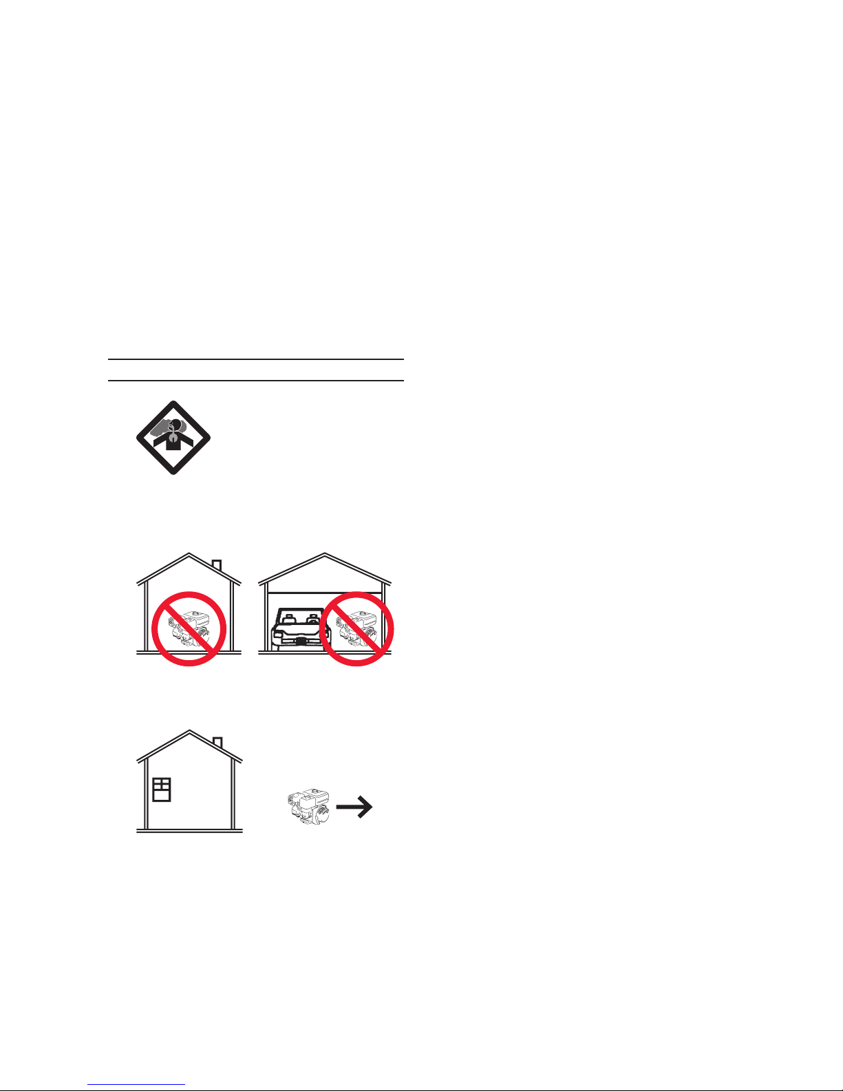
if gasoline has been spilled. Clean
spilled gasoline before starting
engine. Do not operate near a pilot
light, open ame, or ammable
material, liquids or gases.
Do not touch engine during use. Let16. engine cool down after use.
Never store fuel or other ammable 17. materials near the engine.
Only use a suitable means of18. transport and lifting devices with
sufcient weight bearing capacity
when transporting the Snow Blower.
Secure the Snow Blower on transport19. vehicles to prevent the tool from
rolling, slipping, and tilting.
Do not allow anyone in front of Snow20. Blower, or direct the discharge at
windows or bystanders.
Before use, carefully inspect the area21. where the Snow Blower is to be used,
and remove all foreign objects.
People with pacemakers should22. consult their physician(s) before
use. Electromagnetic elds in close
proximity to a heart pacemaker
could cause pacemaker interference
or pacemaker failure. Caution is
necessary when near the engine’s
magneto or recoil starter.
Use only accessories that are23. recommended by Harbor Freight
Tools for your model. Accessories
that may be suitable for one piece of
equipment may become hazardous
when used on another piece of
equipment.
Do not operate in explosive24. atmospheres, such as in the
presence of ammable liquids, gases,
or dust. Gasoline-powered engines
may ignite the dust or fumes.
Stay alert, watch what you are25. doing and use common sense when
operating this piece of equipment.
Do not use this piece of equipment
while tired or under the inuence of
drugs, alcohol or medication.
Do not overreach. Keep proper26. footing and balance at all times.
This enables better control of the
equipment in unexpected situations.
Use this equipment with both hands27. only. Using equipment with only
one hand can easily result in loss of
control.
Dress properly. Do not wear loose28. clothing or jewelry. Keep hair,
clothing and gloves away from
moving parts. Loose clothes, jewelry
or long hair can be caught in moving
parts.
Parts, especially exhaust system29. components, get very hot during use.
Stay clear of hot parts.
Do not cover the engine or equipment30. during operation.
Keep the equipment, engine, and31. surrounding area clean at all times.
Use the equipment, accessories, etc.,32. in accordance with these instructions
and in the manner intended for the
particular type of equipment, taking
into account the working conditions
and the work to be performed. Use
of the equipment for operations
different from those intended could
result in a hazardous situation.

Page 7For technical questions, please call 1-800-444-3353.SKU 67456
Do not operate the equipment with33. known leaks in the engine’s fuel
system.
This product contains or, when34. used, produces a chemical known
to the State of California to cause
cancer and birth defects or other
reproductive harm. (California Health
& Safety Code § 25249.5, et seq.)
When spills of fuel or oil occur, they35. must be cleaned up immediately.
Dispose of uids and cleaning
materials as per any local, state,
or federal codes and regulations.
Store oil rags in a bottom-ventilated,
covered, metal container.
Keep hands and feet away from36. moving parts. Do not reach over or
across equipment while operating.
Before use, check for misalignment37. or binding of moving parts, breakage
of parts, and any other condition
that may affect the equipment’s
operation. If damaged, have the
equipment serviced before using.
Many accidents are caused by poorly
maintained equipment.
Use the correct equipment for the38. application. Do not modify the
equipment and do not use the
equipment for a purpose for which it
is not intended.
Vibration Hazard:
This tool vibrates during use.
Repeated or long-term exposure to
vibration may cause temporary or
permanent physical injury, particularly
to the hands, arms and shoulders. To
reduce the risk of vibration-related
injury:
Anyone using vibrating tools regularly1. or for an extended period should
rst be examined by a doctor and
then have regular medical check-
ups to ensure medical problems are
not being caused or worsened from
use. Pregnant women or people
who have impaired blood circulation
to the hand, past hand injuries,
nervous system disorders, diabetes,
or Raynaud’s Disease should not use
this tool. If you feel any symptoms
related to vibration (such as tingling,
numbness, and white or blue ngers),
seek medical advice as soon as
possible.
Do not smoke during use. Nicotine2. reduces the blood supply to the
hands and ngers, increasing the risk
of vibration-related injury.
Wear suitable gloves to reduce the3. vibration effects on the user.
Use tools with the lowest vibration4. when there is a choice between
different processes.
Include vibration-free periods each5. day of work.
Grip tool as lightly as possible (while6. still keeping safe control of it). Let
the tool do the work.
To reduce vibration, maintain the tool7. as explained in this manual. If any
abnormal vibration occurs, stop use
immediately.

Page 8 For technical questions, please call 1-800-444-3353. SKU 67456
SERVICE PRECAUTIONS
Before service, maintenance, or1. cleaning:
Turn the engine switch to itsa. “OFF” position.
Allow the engine to completelyb. cool.
Then, remove the spark plugc. wire(s) from the spark plug(s).
Keep all safety guards in place and2. in proper working order. Safety
guards include mufer, air cleaner,
mechanical guards, and heat shields,
among other guards.
Do not alter or adjust any part of3. the equipment or its engine that
is sealed by the manufacturer
or distributor. Only a qualied
service technician may adjust
parts that may increase or
decrease governed engine speed.
Wear ANSI-approved safety goggles,4. heavy-duty work gloves, and dust
mask/respirator during service.
Maintain labels and nameplates5. on the equipment. These carry
important information. If unreadable
or missing, contact Harbor Freight
Tools for a replacement.
Have the equipment serviced by a6.
qualied repair person using only
identical replacement parts. This
will ensure that the safety of the
equipment is maintained. Do not
attempt any service or maintenance
procedures not explained in this
manual or any procedures that you
are uncertain about your ability to
perform safely or correctly.
Store equipment out of the reach of7. children.
Follow scheduled engine and8. equipment maintenance.
Refueling Precautions:9.
Do not smoke, or allow sparks,a.
ames, or other sources of ignition
around the equipment, especially
when refuelling.
Do not rell the fuel tank while the b. engine is running or hot.
Do not ll fuel tank to the top. Leave c. a little room for the fuel to expand as
needed.
Refuel in a well-ventilated area only.d.
After refueling, allow fumes toe. evaporate prior to starting the
engine.
SAVE THESE
INSTRUCTIONS.

Page 9For technical questions, please call 1-800-444-3353.SKU 67456
BASIC SPECIFICATIONS
Engine Rating 5.5 Horsepower, Recoil
Start, EPA certied
Fuel Type 89+ octane unleaded
gasoline
Capacity 1 Gallon
Engine Oil Type
SAE 10W-30
(above 32° F)
SAE 5W-30
(at 32° F or below)
Capacity 0.63 Quarts
Sound Level 87 dB
Tire 13” x 4.10 - 6 NHS, 4 PR
24 PSI
Drive Gears
Five Forward:
0.9, 1.2, 1.5, 1.8, 2.5 mph
Two Reverse:
0.9, 1.2 mph
Snow Throwing
Distance Up to 50 Ft.
Accessories
Spark Plug Wrench, (3)
Double Sided Wrenches,
Accessory Pouch, Plastic
Snow Removal Tool
Note: Additional specications found
in the TECHNICAL ENGINE
SPECIFICATIONS chart in this
manual.
The emission control system for
this Generator’s Engine is warranted for
standards set by the U.S. Environmental
Protection Agency. For warranty
information, refer to the last pages of this
manual.
At high altitudes, the engine’s
carburetor, governor (if so equipped), and
any other parts that control the fuel-air
ratio will need to be adjusted by a qualied
mechanic to allow efcient high-altitude
use and to prevent damage to the engine
and any other devices used with this
product.
UNPACKING
When unpacking, make sure that the
item is intact and undamaged. If any parts
are missing or broken, please call Harbor
Freight Tools at 1-800-444-3353 as soon
as possible.

Page 10 For technical questions, please call 1-800-444-3353. SKU 67456
SET UP INSTRUCTIONS
Read the ENTIRE IMPORTANT
SAFETY INFORMATION
section at the beginning of this
manual including all text under
subheadings therein before set
up or use of this product.
TO PREVENT
SERIOUS INJURY
FROM ACCIDENTAL
STARTING:
Turn the Power Switch of the
equipment to its “OFF”
position, wait for the engine to
cool, and disconnect the
spark plug wire(s) before
assembling or making any
adjustments to the equipment.
TO PREVENT
SERIOUS INJURY:
Operate only with proper
spark arrestor installed.
Operation of this equipment
may create sparks that
can start res around dry
vegetation.
A spark arrestor may be
required.
The operator should contact
local re agencies for laws
or regulations relating to re
prevention requirements.
Note: For additional information regarding
the parts listed in the following pages,
refer to the Assembly Diagram near
the end of this manual.
Components and Controls
Figure 1
Upper
Handle
(1D)
Push Frame (43C)
Engine (35C)
Panel (2D)
Gear
Shift
Handle
(44A)
Drive
Control
Skid Plate (4B)
Auger
Control Chute
Control
Lever &
Knob
(12A/9A)
Chute
Assembly
(30A)
Augers
(13B/26B)
Hopper Assembly (1A)

Page 11For technical questions, please call 1-800-444-3353.SKU 67456
ASSEMBLY
Identify all the parts before assembly.1.
Figure 2
Bolts (4A)
Upper
Handle
(1D)
Wing
Knobs
(39A)
Shaped
Washer
(45A)
Push Frame (43C)
2. To attach the Upper Handle (1D) to
the Push Frame (43C):
Hold the Upper Handle (1D) on thea. outside of the Push Frame (43C)
aligning the two holes on each side.
Slide the Bolts (4A) through theb. holes from the outside of the Upper
Handle.
Thread the Wing Knobs (39A) on thec. upper Bolts.
Slide the Shaped Washers (45A)d. and thread the Wing Knobs on the
lower Bolts.
Panel (2D)
Bolts (17D) Lock
Nuts
(19D)
Figure 3
3. To attach the Panel (2D) to the Upper
Handle:
Remove the Bolts (17D), and Locka. Nuts (19D) from the Upper Handle
sides.
Align the Panel over the holes in theb. side of the Upper Handle.
Replace the Bolts and Lock Nuts,c. being careful to replace the spring
on the upper Bolts.
Lock
Nut
(5A)
Gear Connector (48C)
Gear
Shift
Handle
(44A)
Bolt
(38A)
Figure 4
4. To attach the Gear Shift Handle (44A)
to the Gear Connector (48C):
Align the Gear Shift Handle anda. Gear Connector holes.
Attach with Bolts (38A) and Lockb. Nuts (5A).

Page 12 For technical questions, please call 1-800-444-3353. SKU 67456
R-Pin (17A)
Chute
Control
Lever
(12A)
Connecting
Rod (20A)
Figure 5
5. To attach the Chute Control Lever
(12A) to the Connecting Rod (20A):
Insert the Chute Control Lever intoa. the slot at the end of the Connecting
Rod.
Align the holes in both parts andb. insert the R-Pin (17A).
Hopper Assembly (1A)
Chute Assembly (30A)
Brace (33A)
Bolt (32A)
Figure 6
Guard Rail (31A)
Flange
Flange
Gear (24A)
Flange
Chute Assembly (30A)
6. To attach the Chute Assembly (30A)
to the Hopper Assembly (1A):
Thread the looped end of the Guarda. Rail (31A) through the hole in the
left ange of the Chute Assembly
(30A). Insert the other end through
the other ange hole as shown in the
upper photo.
Align the holes in the rim of theb. Chute Assembly with the holes in
the rim of the Hopper Assembly (1A)
opening. Make sure the toothed
section of the rim lines up with the
Gear (24A) so that when the Chute
Assembly is rotated it can face all
the way from the left to the right side
of the Snow Blower.
Attach the Chute to the Hopperc. Assembly, using three Braces (33A)
with Screws (32A) (See Figure 6).

Page 13For technical questions, please call 1-800-444-3353.SKU 67456
To attach the Wheels (57C):7.
With help, lift the unit and slide eacha. Wheel (57C) as far as it will go onto
the Drive Shaft (54C).
There are two holes in each endb. of the Drive Shaft. The inner hole
engages the drive shaft. The outer
hole is for pushing or transporting
the Snow Blower. Slide a Pin (22C)
through the inner hole on each
Drive Shaft and rotate the ring of the
Pin over the drive shaft to lock it in
place.
OPERATING INSTRUCTIONS
Read the ENTIRE IMPORTANT
SAFETY INFORMATION
section at the beginning of this
manual including all text under
subheadings therein before set
up or use of this product.
Engine Controls
Ignition Switch
Starter Handle
Spark Plug
Air Cleaner
Fuel Valve Lever
Choke Lever
Recoil Starter
Mufer
Fuel Cap
Fuel Tank
Dipstick
Oil Fill Plug
Figure 7

Page 14 For technical questions, please call 1-800-444-3353. SKU 67456
Starter Handle
Figure 8
Fuel Valve Lever
Choke Lever
ON
OFF
CLOSED
OPEN
Ignition Switch
ON
OFF
Throttle
Primer
Pre-Start Checklist
Inspect engine and equipment
looking for damaged, loose,
and missing parts before
set up and starting. If any
problems are found, do not use
equipment until xed properly.
Checking and Filling Engine Oil
CAUTION! Your Warranty is VOID if
the engine’s crankcase is not
properly lled with oil before each
use. Before each use, check the
oil level. Do not run the engine
with low or no engine oil. Running
the engine with no or low engine
oil WILL permanently damage the
engine.
Clean the Dipstick exterior and the1. area around it. Remove the Dipstick
by threading it counterclockwise, and
wipe it off with a clean, lint free rag.
Reinsert the Dipstick without2. threading it in and remove it to check
the oil level. The oil level should be
between the high and low marks on
the Dipstick.
If the oil level is at or below the low3. mark: Wipe the Oil Fill Plug (opposite
the dipstick), remove it, and add the
appropriate type of oil through it’s
hole until the oil level is between
the high and the low marks. Do not
overll.
Oil type:
above 32° F = SAE 10W-30
32° F or below = SAE 5W-30
Replace the Oil Dipstick by threading4. it clockwise.
CAUTION! Do not run the engine with too
little or too much oil. The engine will
be permanently damaged.

Page 15For technical questions, please call 1-800-444-3353.SKU 67456
Checking and Filling Fuel
WARNING! TO PREVENT
SERIOUS INJURY FROM
FIRE:
Fill the fuel tank in a well-
ventilated area away from ignition
sources. If the engine is hot from
use, shut the engine off and wait for it
to cool before adding fuel. Do not
smoke.
Clean the Fuel Cap and the area1. around it.
Unscrew and remove the Fuel Cap.2.
If needed, ll the Fuel Tank to about 3.
1 inch under the ll neck of the
gasoline tank with 89 octane or better
unleaded gasoline.
Then replace the Fuel Cap, turning it4. counterclockwise to tighten.
Wipe off any spilled fuel and allow5. excess to evaporate before starting
engine. To prevent FIRE, do not start
the engine while the smell of fuel
hangs in the air.
Starting the Engine
Start Procedure
Before starting the engine:
Follow the Set Upa. Instructions to prepare the
equipment.
Inspect the equipment andb. the engine.
Fill the engine with properc. amount and type of fuel and
oil.
Read the Equipmentd. Operation section.
IMPORTANT: Make sure that both the
Auger Control and Drive Control are
disengaged. Know how to start and
stop the engine and how to operate
all controls before starting the engine.
Slide the Throttle to the FAST1. position.
Note: The Throttle is located on the engine
as shown in Figure 8. Some tools
have a Speed Control Lever located
elsewhere on the tool which functions
the same as the Throttle. Use the
Speed Control Lever instead of the
Throttle when the tool is so equipped.
Adjust the Choke as follows:2.
For a cold engine move the Chokea. Lever to the CLOSED position and
push the Primer button two or three
times. Additional priming may be
necessary if the temperature is
below 15°F.
For a warm engine, leave the Chokeb. Lever in the OPEN position and do
not push the Primer button.
If the engine is cold, give the Starter3. Handle a few gentle pulls to allow
the gasoline to ow into the Engine’s
carburetor.
Pull the Starter Handle gently until4. resistance is felt. Allow Cable to
retract fully and pull forcefully, rapidly,
all the way out. Repeat this step until
the engine starts.
Note: Be careful to pull to the side of the
Snow Blower when pulling the Starter
Handle to avoid scraping against the
side of the Handle and Panel.
Once the Engine starts, hold the5. Starter Handle loosely, guiding it as it
recoils so it doesn’t hit the engine.

Page 16 For technical questions, please call 1-800-444-3353. SKU 67456
Allow the Engine to run for several6. seconds. Then, if the Choke lever is
in the CLOSED position, move the
Choke Lever very slowly to its OPEN
position.
Note: Moving the Choke Lever too fast
could kill the engine.
IMPORTANT: Allow the engine to run7.
at no load for ve minutes after each
start-up to stabilize the engine.
Adjust the Throttle between its “LOW” 8.
to “HIGH” position as needed to
maintain power to the engine.
Break-in Period
Breaking-in the engine will help in1. prolonging its life.
The operational break-in period will2. last about 3 hours of use. During this
period:
Do not apply a heavy load to the• equipment.
Do not operate the engine at its• maximum speed.
The maintenance break-in period will3. last about 20 hours of use. After this
period:
Change the engine oil.•
Under normal operating conditions
subsequent maintenance follows
the schedule explained in the
MAINTENANCE AND SERVICING
section.
To Stop The Engine
To stop the engine in an emergency,1. turn the Ignition Switch off.
Under normal conditions, use the2. following procedure:
With the engine running, pull thea. Starter rope with a rapid, continuous
full arm stroke three or four times.
This will produce a loud clattering
sound which is not harmful to the
engine.
Slide the Throttle to stop.b.
Turn the Ignition Switch to off.c.
Wipe all snow and moisture fromd. the area around the engine as well
as the area in and around the drive
control.
Operating the Snow Blower
Set Up
Loosen the Bolts (5B) holding the1. Skid Plates (4B) and adjust the level
of the skid plates for the terrain. On
smooth sidewalks, set the Skid Plate
to its highest position so the Hopper
Assembly (1A) is almost touching the
ground. For uneven surfaces, set the
Skid Plate lower to give the Hopper
Assembly more clearance.
WARNING: Do not use the Snow Blower
on rocky or gravel surfaces. Such
materials can be drawn up into the
machine, damage the machine and/
or cause injury to bystanders when
ejected from the Chute.
Loosen the Knobs (26A) on the side2. of the Chute Cap (28 A), rotate the
Cap to the desired position, then
retighten the Knobs. This determines
the distance that snow is thrown.
Setting the Chute Cap down causes
the snow to be thrown a short
distance, while setting it up will throw
snow farther.

Page 17For technical questions, please call 1-800-444-3353.SKU 67456
Operation
Follow the Set up procedures and1. understand all the controls and how
to start and stop the engine and
Snow Blower.
Check the fuel and oil level of the2. engine.
Start the engine.3.
Keep the engine Throttle in the fast4. position and only use the Gear Shift
Handle to adjust the speed.
Move the Gear Shift Handle to one5.
of the ve forward positions or two
reverse positions. Select the speed
appropriate for the snow conditions
and a pace that you are comfortable
with. Use a slower speed until you
are comfortable and familiar with the
operation of the Snow Blower.
Squeeze the Auger Control against6. the handle to power the auger.
Release it to stop.
Squeeze the Drive Control against7. the handle to power forward or
reverse travel of the Snow Blower.
Release it to stop.
IMPORTANT: Do not reposition the Gear
Shift Handle (44A) (change speeds
or direction of travel) without rst
releasing the drive control and
bringing the Snow Blower to a
complete stop. Doing so will result in
premature wear to the Snow Blower’s
drive system.
After completing the task, run the8. engine for a few minutes to melt any
snow or ice from the unit.
Release the Auger and Drive9. Controls, turn off the engine and
allow it to cool enough to clean.
Clean the entire Snow Blower
thoroughly after each use and wipe
dry.
Snow Blower Practices
Snow is easier to remove when ita. is freshly fallen and/or in the early
morning hours before it has been
warmed by the sun.
When adjusting the gears, use lowerb. speeds for heavier snow, and higher
speeds for softer snow and for
transporting the Snow Blower.
Overlap each successive pathc. slightly to ensure complete removal
of snow from the area. If the snow
is extremely heavy, work over the
same path twice before moving to
the adjacent section.
Direct the Chute downwindd. whenever possible.
Keep the engine clean and clear ofe. snow during use. This will help air
ow while extending the life of the
engine.
Chute Clean-out
WARNING: The mufer, engine and
surrounding areas become hot. Stay
clear of hot parts of the Snow Blower
and engine. Turn the engine off
before cleaning the Chute
To clean the Chute:
Release both the Auger Control anda. the Drive Control.
Stop the engine.b.
Remove the clean-out tool from thec. clip on the Hopper Assembly (1A).
Use the shovel-shaped end of thed. clean-out tool to dislodge and scoop

Page 18 For technical questions, please call 1-800-444-3353. SKU 67456
any snow and ice which has formed
in and near the chute assembly.
Always keep your hands a safee. distance from the Chute
Refasten the clean-out tool to thef. clip on the auger housing, and start
the snow Blower’s engine.
TECHNICAL
SPECIFICATIONS
Engine Type Horizontal Single
Cylinder 4 stroke OHV
Recoil Start
Bore x Stroke 68 x 45
Compression Ratio 8.5:1
Displacement 163cc
Rotation viewed from PTO
(power takeoff - the output shaft) Counterclockwise
Fuel Type 89+ octane unleaded
gasoline
Capacity 1 Gallon
Engine Oil Type
SAE 10W-30
(above 32° F)
SAE 5W-30
(at 32° F or below)
Capacity 0.63 Quarts
Spark Plug Type F7RTC
Gap 0.028-0.031”
(0.7~ 0.8mm)
Valve
Clearance Intake 0.10 ± 0.15 mm
Exhaust 0.15 ± 0.20 mm
Speed Idle 1,400 ± 150 RPM
SERVICING
TO PREVENT
SERIOUS INJURY
FROM ACCIDENTAL
STARTING:
Turn the Power Switch of the
equipment to its “OFF”
position, wait for the engine to
cool, and disconnect the
spark plug wire(s) before
performing any inspection,
maintenance, or cleaning
procedures.
TO PREVENT
SERIOUS INJURY
FROM EQUIPMENT FAILURE:
Do not use damaged
equipment. If abnormal noise,

Page 19For technical questions, please call 1-800-444-3353.SKU 67456
vibration, or excess smoking
occurs, have the problem
corrected before further use.
Maintenance Procedures
Many maintenance procedures,
including those not detailed
in this manual, will need to
be performed by a qualied
technician for safety. If you
have any doubts about your
ability to safely service the
equipment or engine, have a
qualied technician service the
equipment instead.
Note: Warranty is void if proper
maintenance and servicing
procedures are not followed.
Engine Oil Change
CAUTION! Oil is very hot during
operation and can cause burns. Wait
for engine to cool before changing oil.
Place a drain pan (not included)1. underneath the crankcase’s drain
plug.
Remove the drain plug (18) and, if2. possible, tilt the crankcase slightly to
help drain the oil out. Recycle used
oil.
Replace the drain plug and gasket3. (19) and tighten it.
Rell the oil to the proper level 4. following the instructions under the
Starting the Engine section.
Air Filter Element Maintenance
Wipe off the air cleaner cover.1.
The air cleaner cover is held in place2. by a nut (112). Remove it.
Remove the air lter element.3.
Cleaning:4.
The “paper” lter element:a. To prevent injury from dust and
debris, wear ANSI-approved safety
goggles, NIOSH-approved dust
mask/respirator, and heavy-duty
work gloves. In a well-ventilated
area away from bystanders, use
pressurized air to blow dust out of
the air lter from the side opposite
the lter’s normal air ow (the
“clean” side of the lter).
If this does not get the lter
reasonably clean, replace it.
The foam lter element:b. Wash the element in warm water
and mild detergent several times.
Rinse. Squeeze out excess water
and allow it to dry completely. Soak
the lter in lightweight oil briey, then
squeeze out the excess oil.
Install the new lters or the cleaned 5.
lters. Secure the Air Cleaner Cover
before use.
Spark Plug Maintenance
Disconnect spark plug wire from1. end of plug. Clean out debris from
around spark plug.
Using a spark plug wrench, remove2. the spark plug.
Inspect the spark plug:3. If the electrode is oily, clean it using a
clean, dry rag.
If the electrode has deposits on it,
polish it using emery paper.
If the white insulator is cracked or

Page 20 For technical questions, please call 1-800-444-3353. SKU 67456
chipped, the spark plug needs to be
replaced.
When installing a new spark4. plug, adjust the plug’s gap to the
specication on the Technical
specication chart. Do not pry
against the electrode or the insulator,
the spark plug can be damaged.
Install the new spark plug or the5. cleaned spark plug into the engine.
Gasket-style: Finger-tighten until the
gasket contacts the cylinder head,
then about 1/2-2/3 turn more.
Non-gasket-style: Finger-tighten until
the plug contacts the head, then
about 1/16 turn more.
Apply a small amount of dielectric6. grease (not included) to the insulator
of the spark plug and attach the wire
securely to the spark plug.
Fuel Filter Replacement
WARNING! TO PREVENT
SERIOUS INJURY FROM
FIRE:
Clean the fuel lter in a well-
ventilated area away from ignition
sources. Do not smoke.
Wait for the engine to cool completely1. before proceeding.
Wear protective gear including, ANSI-2. approved safety goggles, NIOSH-
approved dust mask/respirator, and
nitrile gloves.
The Fuel Filter (125) is attached to3. the inside of the Fuel Cap (123).
Remove the Cap with the lter, and 4.
clean the lter of any debris. Replace
the cap with the lter attached.
Clean up and properly dispose of any5. spilled fuel.
Wait for at least one hour before use6. to allow all residual fuel vapors to
dissipate. To prevent FIRE, do not
start the engine while the smell of
fuel hangs in the air. Remember to
open the fuel valve before restarting
the engine. It may take a little
longer than usual to start the engine
because the fuel needs to rell the
fuel line and new lter.
Cleaning, Maintenance, and
Lubrication Schedule
Note: This maintenance schedule
is intended solely as a general
guide. If performance decreases
or if equipment operates unusually,
check systems immediately. The
maintenance needs of each piece
of equipment will differ depending
on factors such as duty cycle,
temperature, air quality, fuel quality,
and other factors.
Note: These procedures are in addition to
the regular checks and maintenance
explained as part of the regular
operation of the engine and
equipment.
After Initial 20 Operation Hour Period:
Change engine oil.a.
Every 25 Operation Hours Thereafter:
Clean/replace air lter element.a.
Inspect/clean spark plug.b.
Every 50 Operation Hours:
Change engine oil.a.
Replace fuel lter (if equipped).b.
Table of contents